

Page 1
Page 2
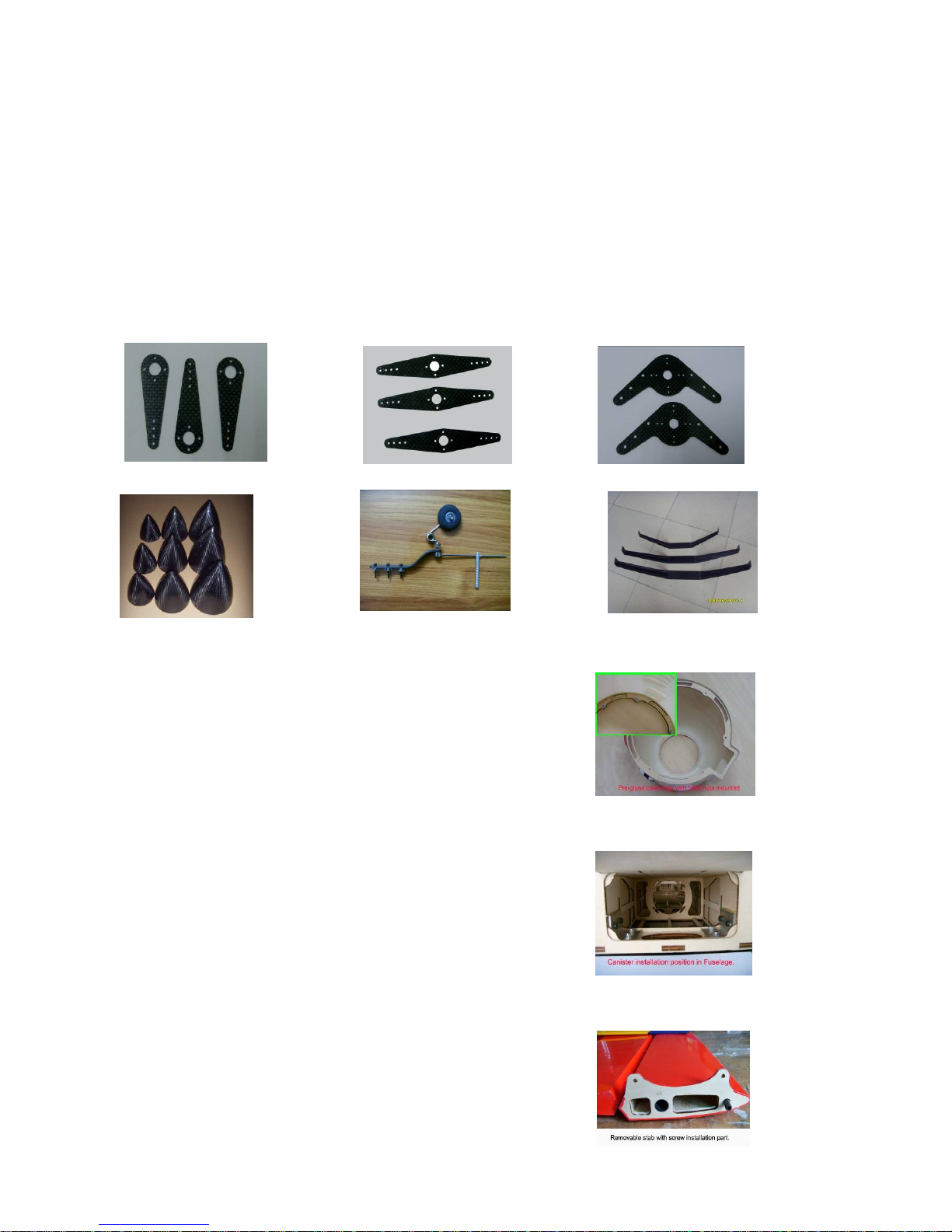
Our airplane model:
1 All our plane have the matching carbon fiber servo arms, carbon
fiber main and tail landing gear, carbon fiber spinner and wood
propeller available.
2
3
4 Removable wings and stabs
Pre-glued cowling ring with
blind nuts mounted.
Canister installation position
in Fuselage
Page 3
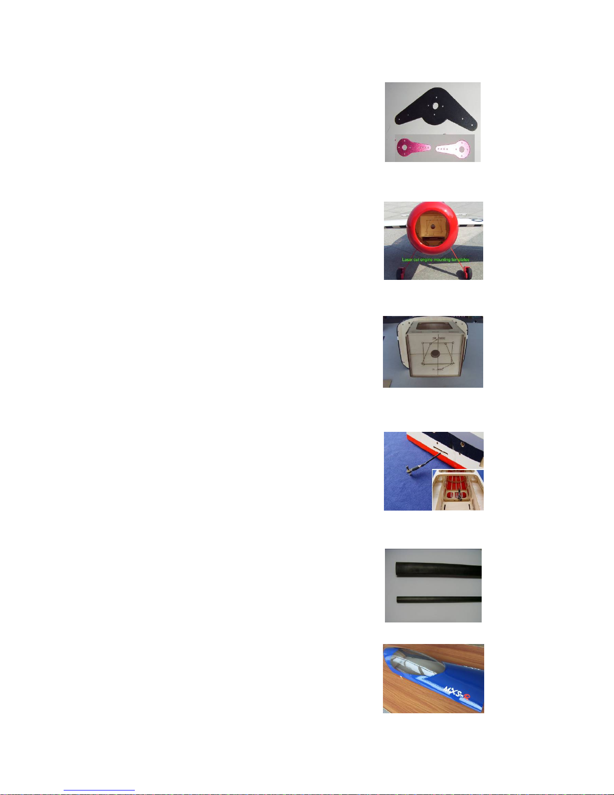
5 Pre drilled servo control horns
6
7 Pre installed firewall
8 Pre install pull pull wire with
ball links on rudder
9 Carbon Fiber wing tube include
10 Floor and dashboard for cockpit
Laser cut engine mounting
templates
Page 4

Caution!
1 You should not regard this plane as a toy!
2 To ensure safety, please read this instruction manual thoroughly
before assembly.
3 Building and operating a model plane requires diligent practice and
correct guidance. An inexperienced flyer can cause serious injury
and property damage.
4 Seek the assistance of an experienced RC pilot or model airplane
club for help with assembly, operation and maintenance to ensure
your flying experience is both enjoyable and safe.
5 Fly only in AMA (Academy of Model Aeronautics) approved areas.
Approved areas or areas approved by the Model Association of
your country.
Page 5
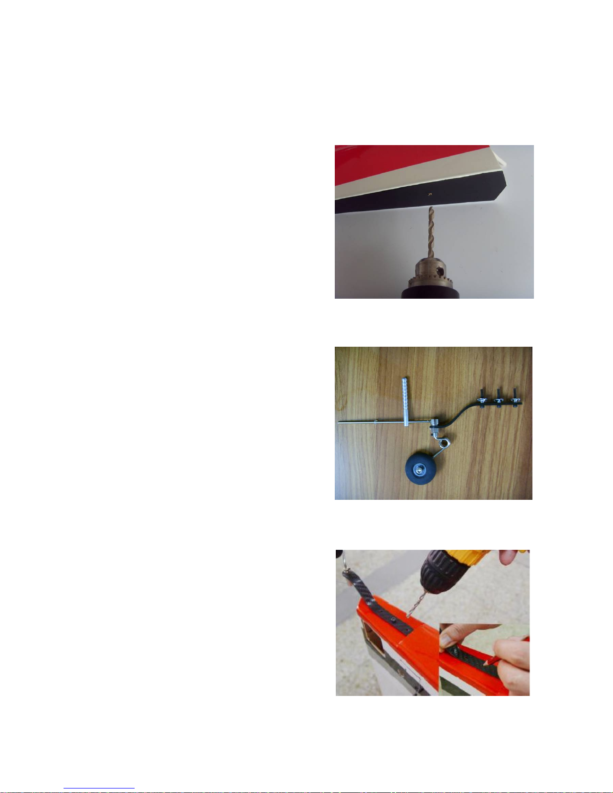
Main Landing Gear and Tail Wheel Unit
Tail Wheel Unit
1
2
3
Drill a hole and make it fit
the steering tube.
Do not glue it into position untill the tail
wheel installation step is completed.
Assembly photo for the tail
wheel parts.
Use the tail wheel bracket as
a template and drill holes for
the mounting bolts.
Page 6
4
5
6
7
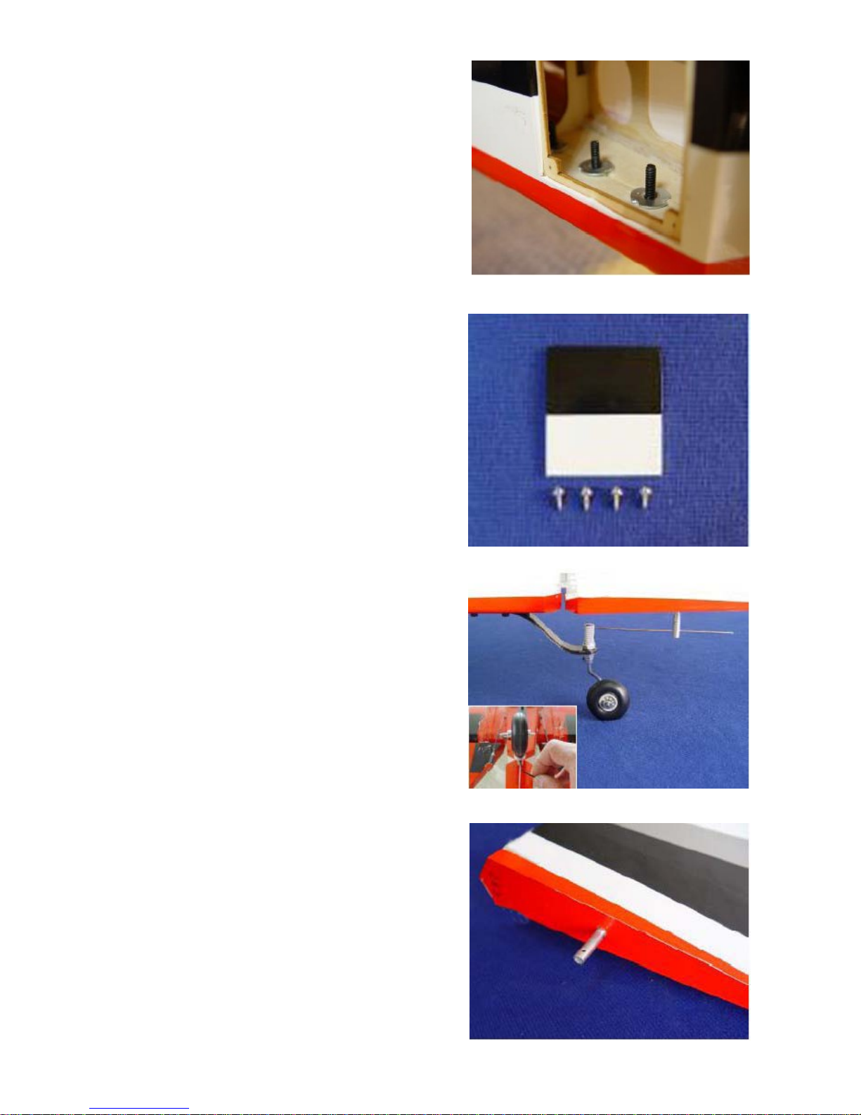
Insert the steering arm into
the rudder steering tube and
position the tube ready for
gluing. Tighten the set nuts.
Epoxy the steering tube in
place as shown.
Install the blind nuts through
the openning in the rear of
the fuselage.
Attach the tail wheel bracket
and secure the bolts with
Blue Loctite.
Install the hatch with 4 selftapping screws
Page 7
Main Landing Gear Istallation
1
2
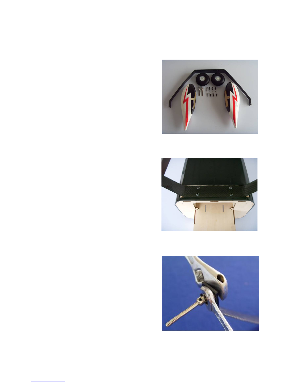
Install the landing gear in the
pre-drilled holes with the
supplied bolts and locking
nuts.
Secure the bolts with Blue
Loctite
Install the landing gear axles
with lock nuts but do not
tighten yet.
All parts for the main landing
gear
Page 8
3
4
5
6
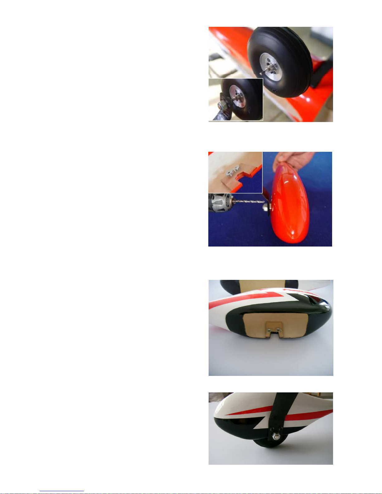
Mount the wheel pants and
secure the bolts with a drop
of Blue Loctite.
Install the wheel and tighten
the collar set screw using a
drop of Blue Loctite. Make
sure the wheel rotates freely.
Slipping the wheel pant over
the axles and mark the
position for the two attached
bolts.
Drill the holes for the
attached bolts and install the
blind nuts as shown.
Page 9
Main Wing Assembly
1
2
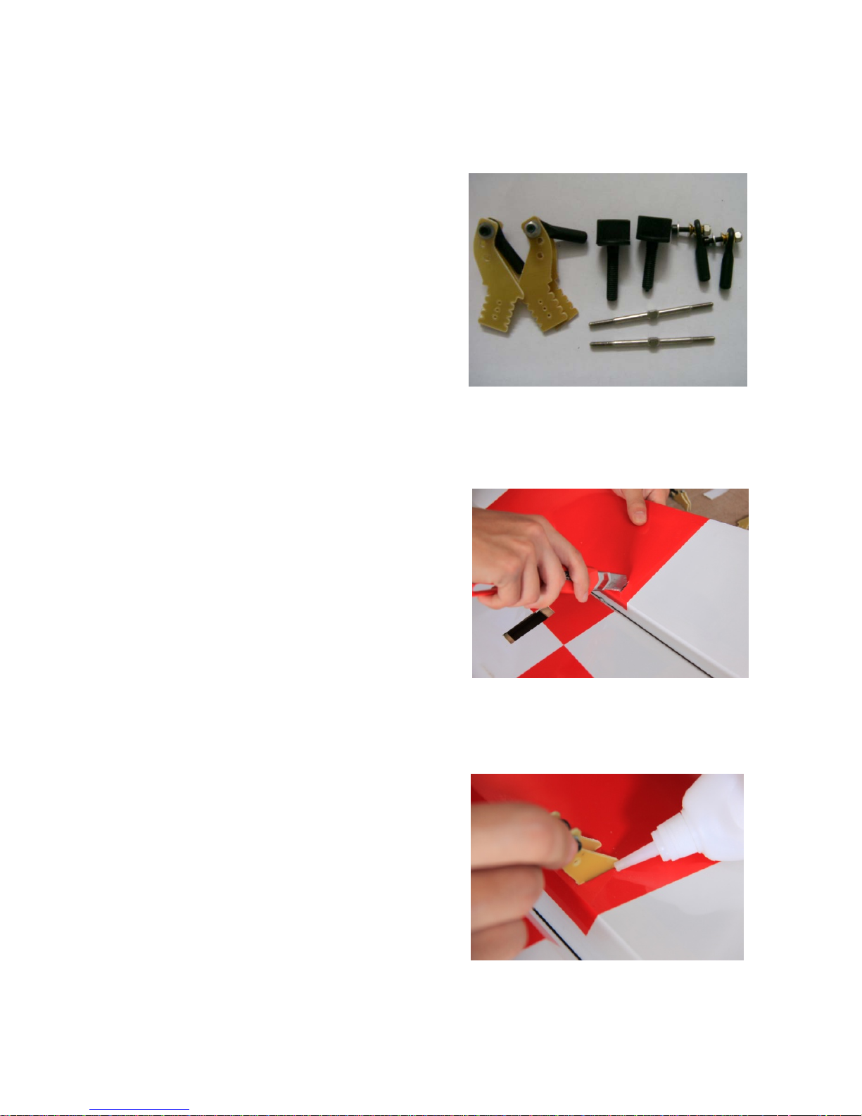
Parts for Main wing
installation
Remove the covering from
the servo position. Find out
the slot pre-opened for
rudder control horn, remove
the film. as shown.
Fit the control horn into the
slot, glue the horns into the
aileron of each side.
Page 10
3
4
5
Put the servo into the servo
hole, and mark the position
for the screw to fixup the
servo. Pull the extension lead
through to the root of the
wing.
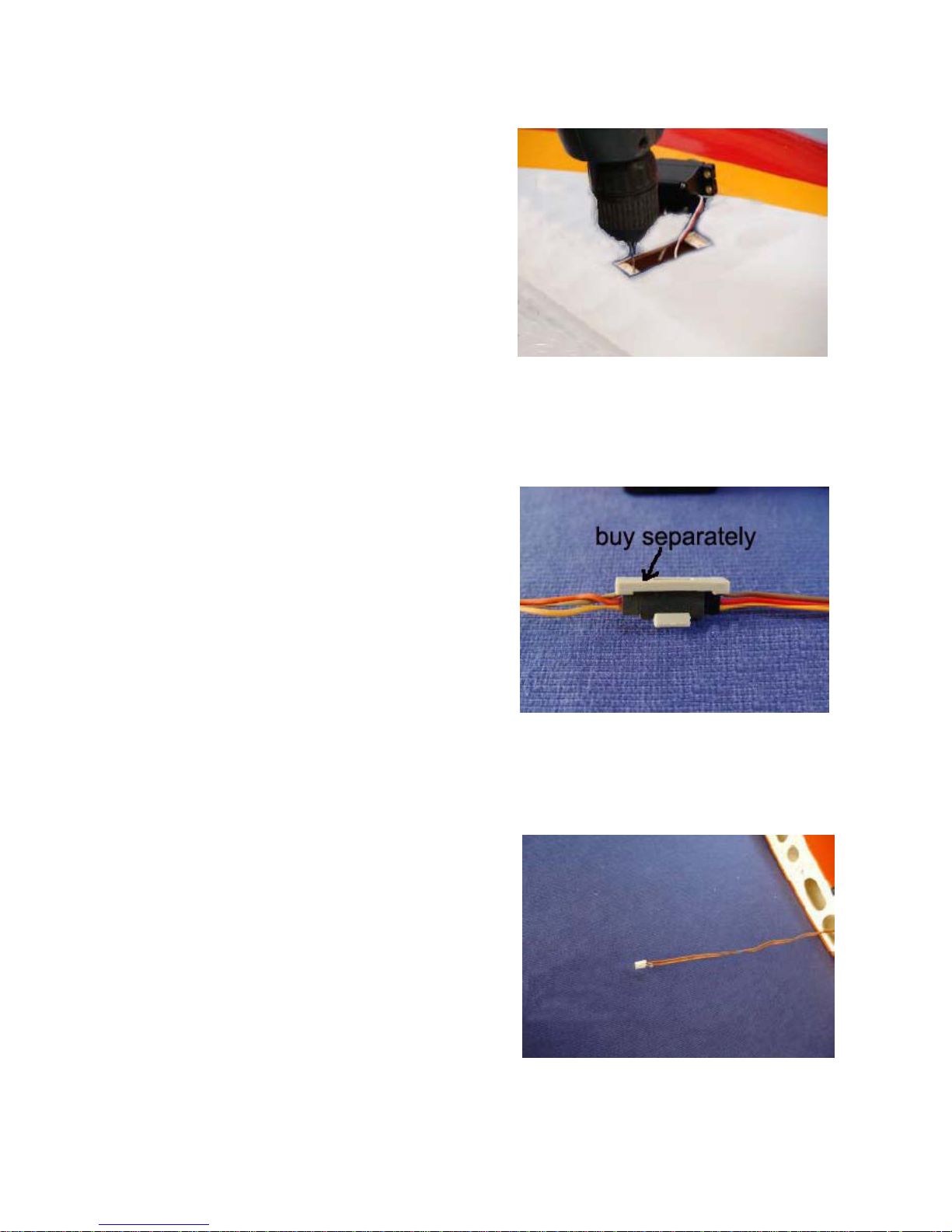
Drill holes for the servo
mounting screws and harden
the wood around the holes
with a drop of thin CA.
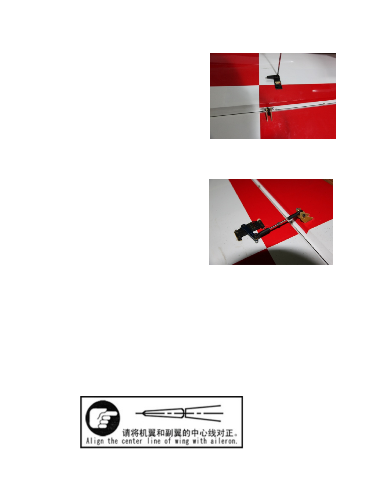
Use the safety clips (buy
separately) to secure the
servo and servo extension
connected.
Page 11
6
7
8
Attn:
Drill holes for the servo
mounting screws and harden
the wood around the holes
with a drop of thin CA.
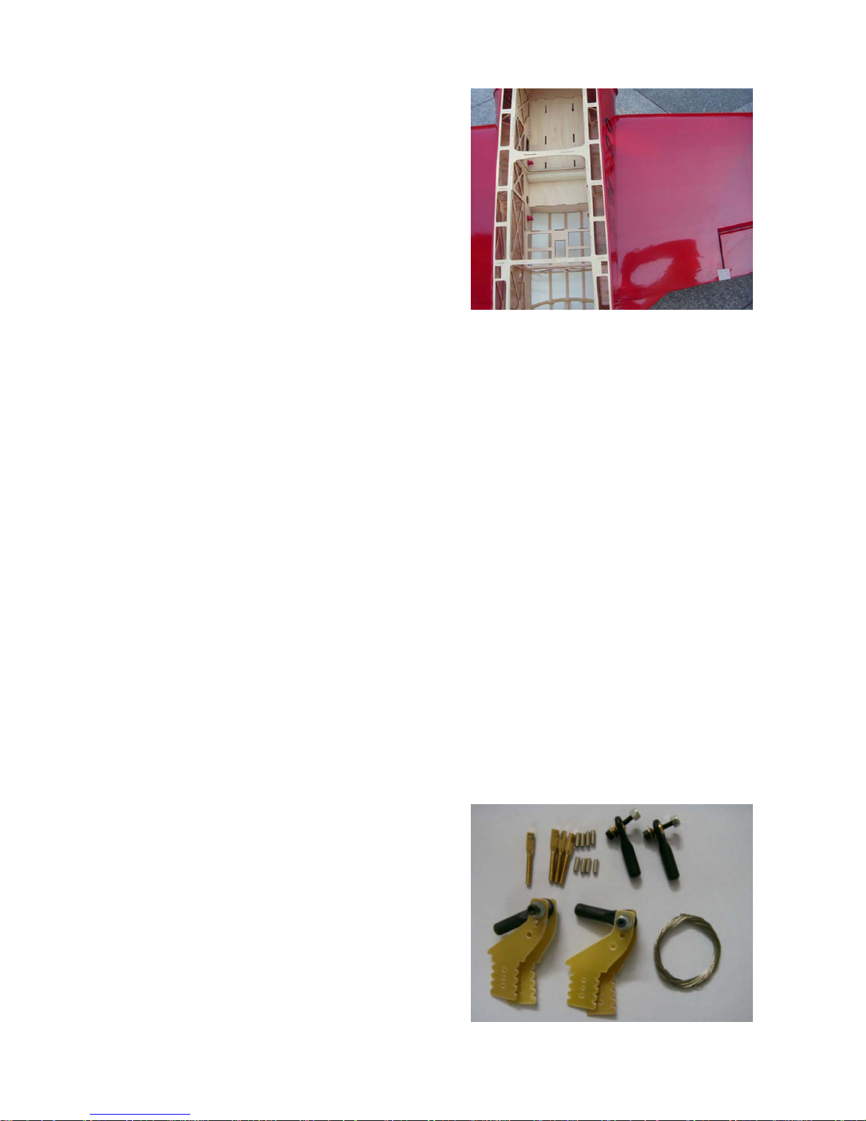
Install the control horn.
Adjust the horn and servo
arm. Fix the horn in place
firmly. Install the ball link and
push rod . Make sure it’s firm
and flexible.
Repeat the previous steps for
the other wing.
Please install the wing tube
and wing bolts in the final
assembly.
Page 12
9
Rudder Installation
Connect the two wings with
carbon fiber tube and four
nylon screw supplied.
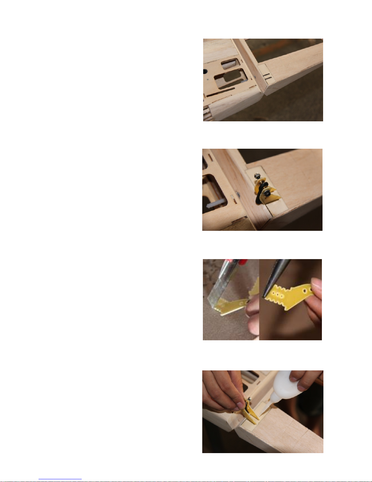
Parts for Rudder installation
Page 13
1
2
3
4
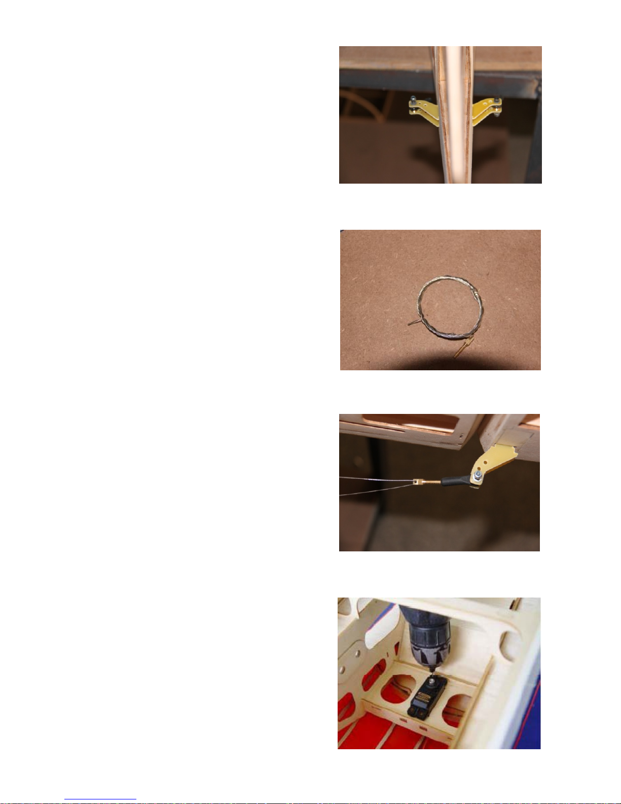
Find out the slot pre-opened
for rudder control horn,
remove the film
Fit the control horn into the
slot, meansure the correct
length for it
Cut the longer part
Glue the horns into the
rudder of each side
Page 14
5
6
7
8
Repeat the same method on
the other side of the rudder.
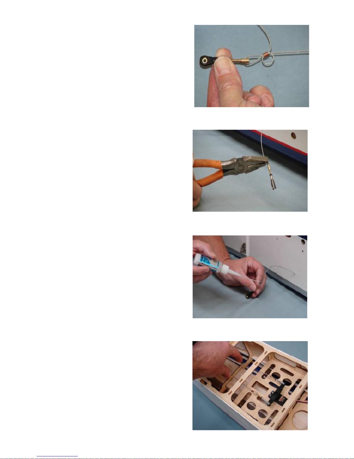
Thread the cable connecter
halfway into the ball link .
Connect the pull-pull wire
and control horn with ball link
Drill holes for the mounting
screws. Fit the servos as
shown with the servo label
facing the rudder. Harden the
area around the holes with a
drop of thin CA.
Page 15
9
10
11
12
Use brass crimps on each
cable and thread, the cable
through the end of the pullpull connector.
Crimp the brass tube with a
crimping tool or pliers
A drop of thin CA may be
applied to the brass tube to
help secure the cable
Install the rudder ball links
with bolts and locking nuts.
Check the pull-pull cables.
Rudder and the rudder servo
should both be in the neutral
position.
Page 16
Stabilizer Installation
1
2
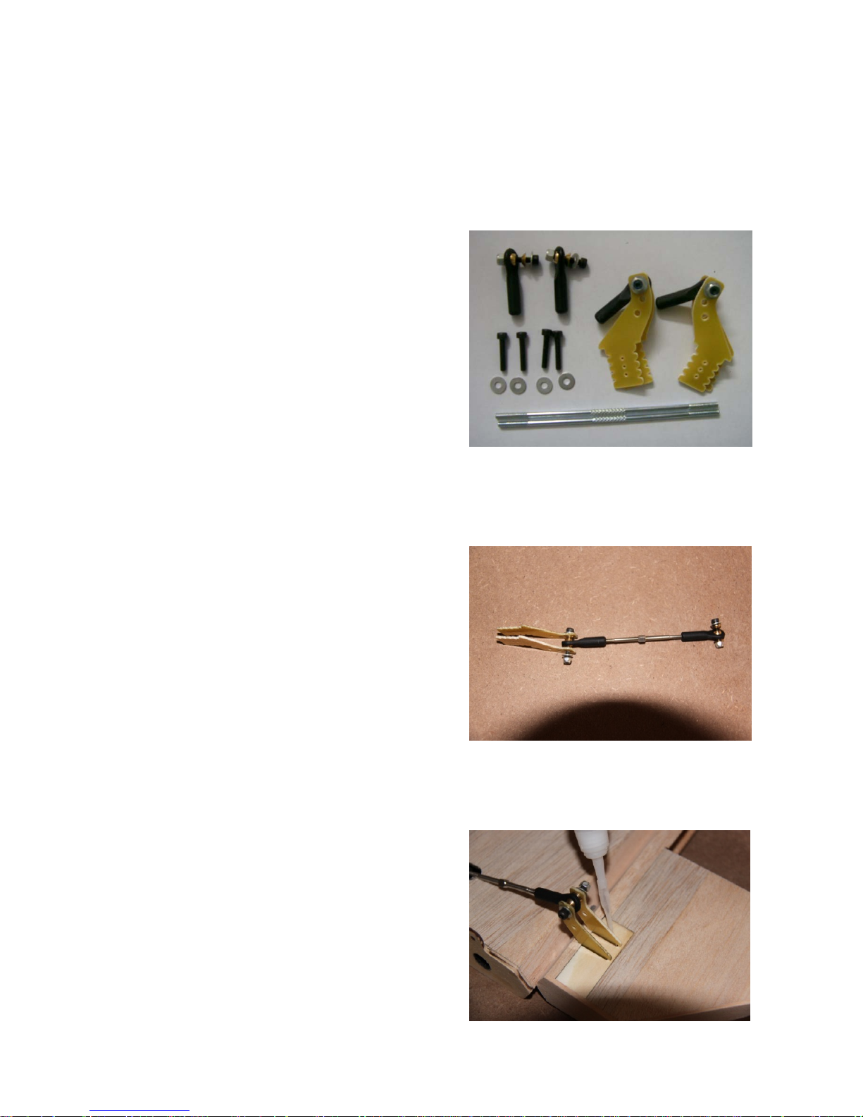
Parts for stabilizer
Connect the pushrod and
control horn as shown
Put the control horn into the
slot pre-opened, glue it to the
stab, on each side
Page 17
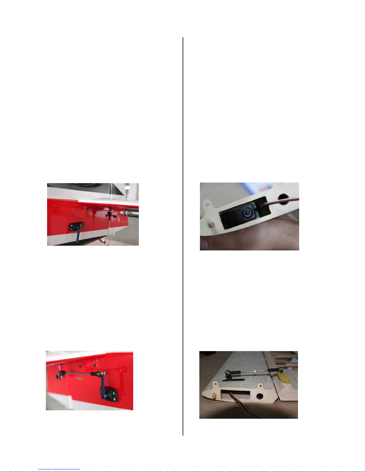
Mxsr 50CC's hidden servo
33
44
Install the servos in the
fuselage in precut locations
on both sides.
Install the elevator servo
as shown
Connect the control horm
and servo arm with ball link
Connect the servo and the
pushrod as in the photo
Sbach 30cc / Sbach 50cc /
Mxsr 30cc's exterior servo
Page 18
5
Attn:
Engine Installation
1
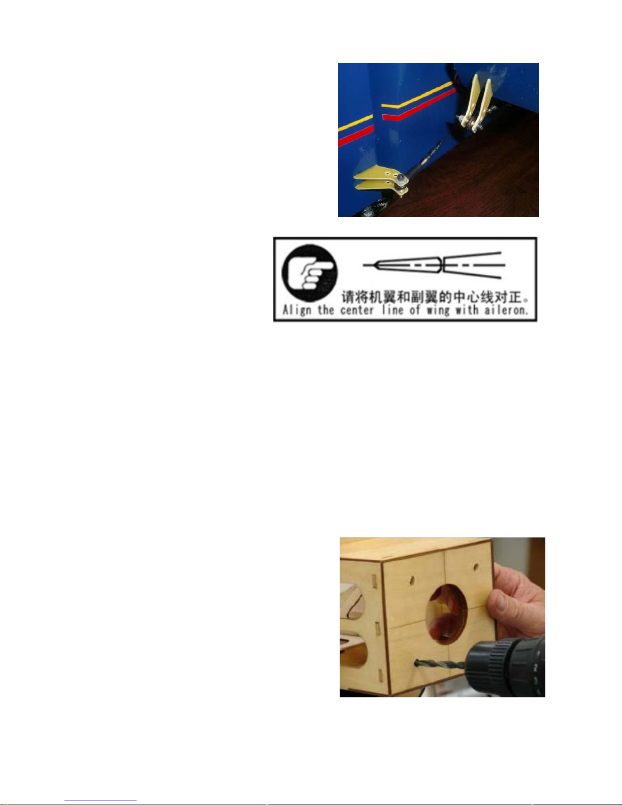
Use a drill to drill screw
holes for engine Installation.
The holes position for 3W &
DL have been lased on the
firewall.
Repeat the previous steps for
the other wing.
Install the stabilizer tube and
bolts.
Page 19
2
3
4
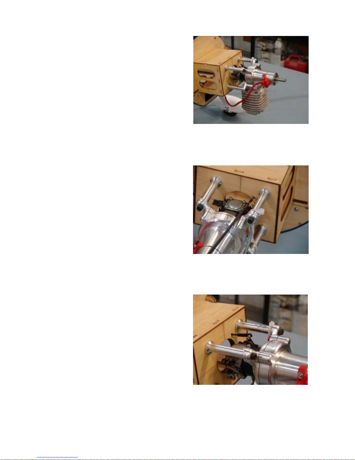
Insert the bolts through flat
fender washers, the firewall
and into the engine stand
offs. Tighten firmly. Secure
mounting bolts nuts with Blue
Loctite.
Use a bit to drill a pushrod
exit hole on the firewall in line
with the engine carburetor
throttle arm.
Attach the ball link to the
throttle pushrod and secure
to the carburetor throttle arm
with a bolt and nylon lock
nut.
Page 20
5
6
7
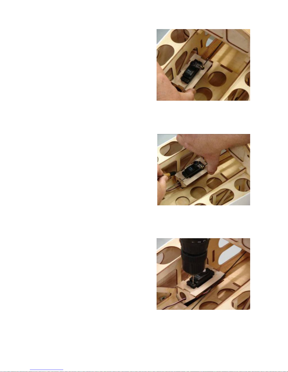
Insert the throttle servo into
the servo mounting tray with
an output arm forward.
Insert the throttle pushrod
into the servo arm easy link.
Use a drill to drill the servo
mounting holes.
Install the servo with servo
screws.
Mark a line for the throttle
servo tray, then glue it to the
fuselage.
Page 21
8
9
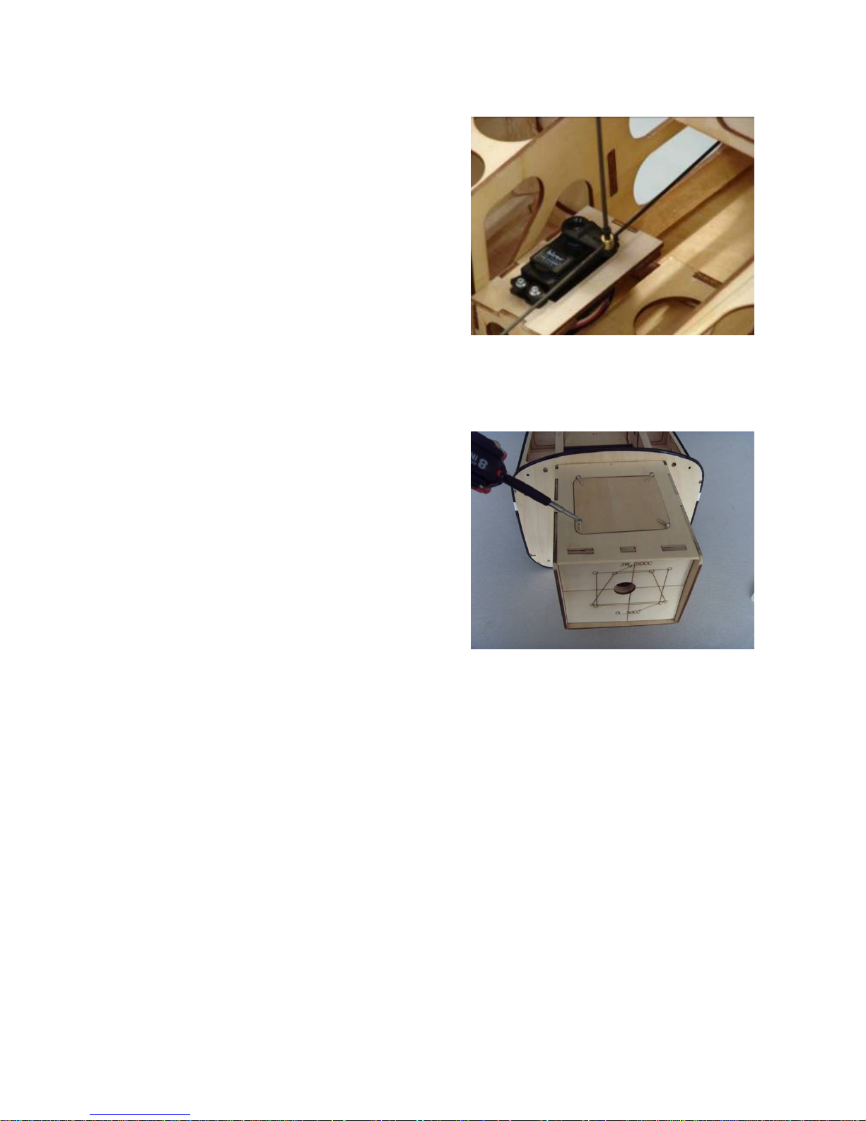
Insert the throttle pushrod
into the servo easy link.
Move the servo arm to the
center position. So that
carburetor is half open.
Tighten the easy link set
screw.
Use self-tapping screw to
fixup the wood to lock the
hatch of the engine box.
Page 22
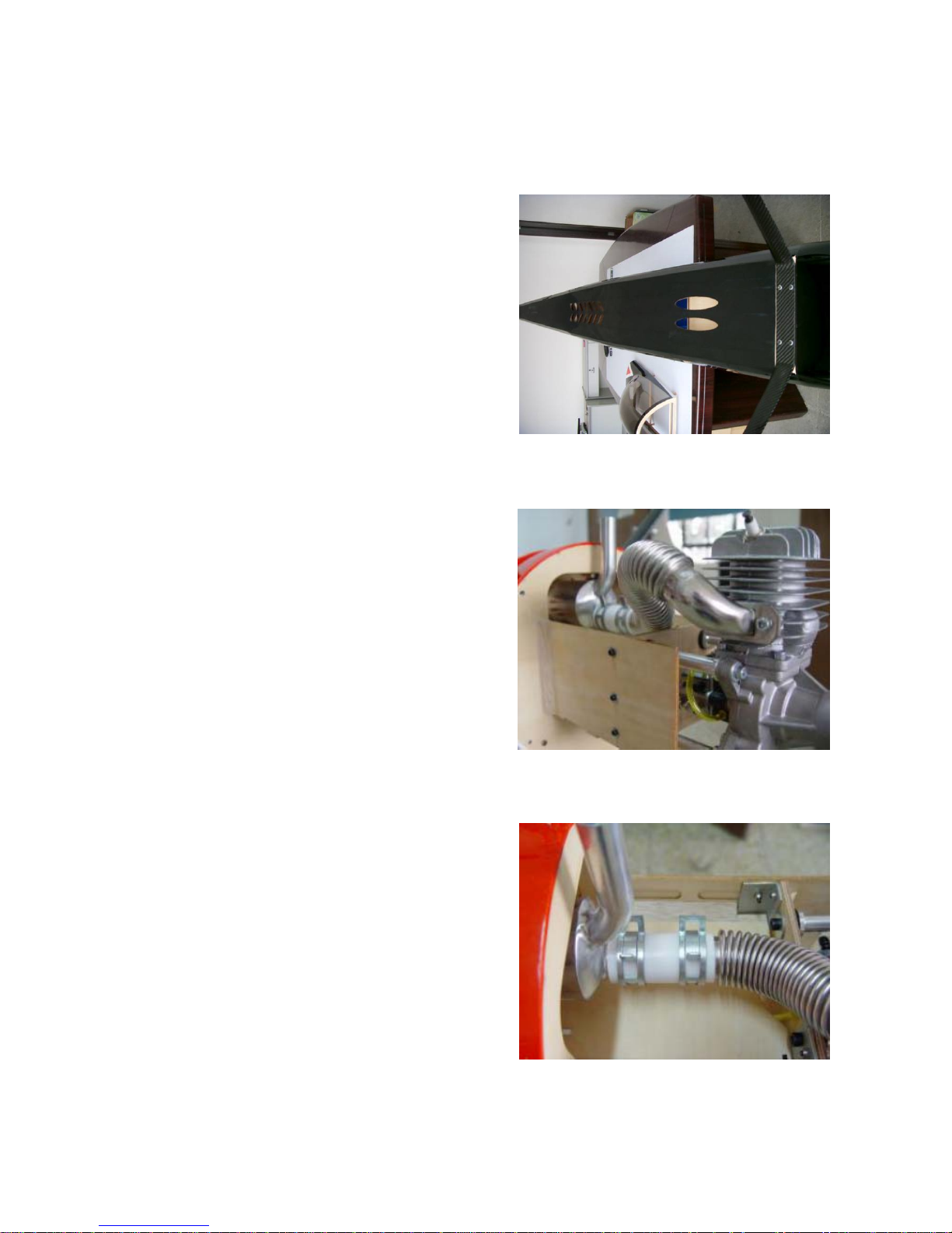
Muffler and Canister
1
2
3
Bend the flexible manifold to
connect to the canister
muffler. Trim the excess pipe
to fit.
Tighten the manifold bolts
and secure with blue loctite.
Use the silicone coupler and
clamps to join the manifold
and the canister muffler as
shown.
Remove the cover from the
pre-cut canister ari exit
openning and ensure the
edge has been sealed.
Page 23
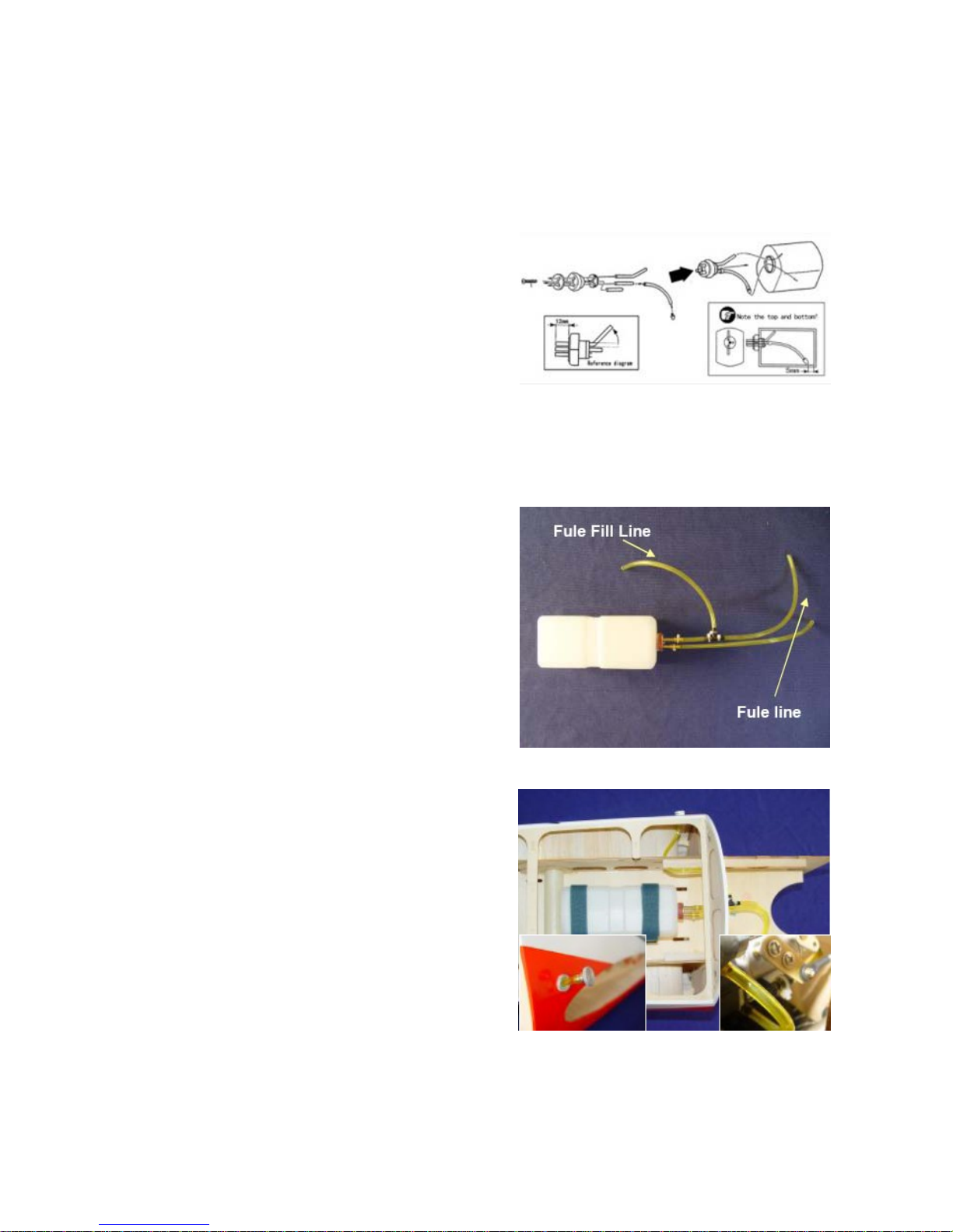
Fuel Tank
1
2
3
Tighten the velcro ties
secure the fuel tank.
Install the inside parts of fuel
tank as shown.
Assembly the outside fuel
pipe as shown.
Page 24
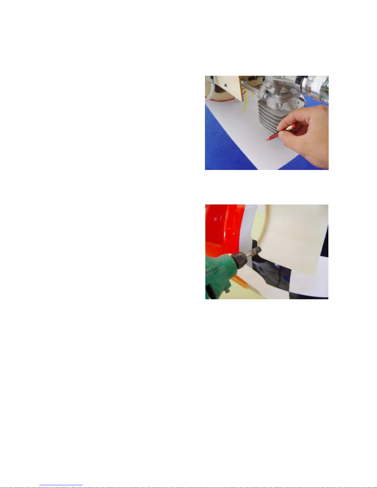
Cowl Assembly
1
2
3
Note: Check the engine
temperature. More cut holes
may be required if the engine
temperature is too high.
Use a fiber cutting tool to
rough out the cowl and finish
with a round sander.
Use templates to cut out
other opennings in the cowl
for manifolds if fitted.
Use a paper template to
measure where the cowl will
need to be cut for the
exhaust and spark plug. Trial
fit to make sure there is a
minimum of 3/8" clear space
around the engine for
Page 25
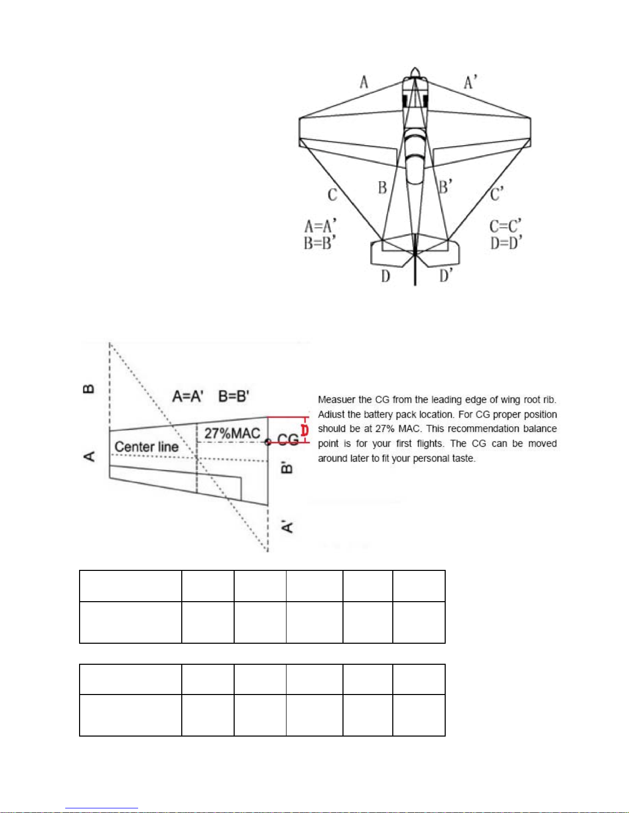
Center of Gravity
Sbach MXSR Yak55 Slick
27% Mac
CG Location 138mm 132mm
Sbach MXSR Yak55 Slick
30% Mac
CG Location 158mm 172mm182mm145mm170mm
Yak5450cc
132mm 100mm 142mm
Your balance at the CG will
determine the fin al mounting
location for batteries. Mount
batteries and secure with
Nylon zip ties.
Yak5430cc
The center of gravity is on
the rear of the wings tube.
Page 26
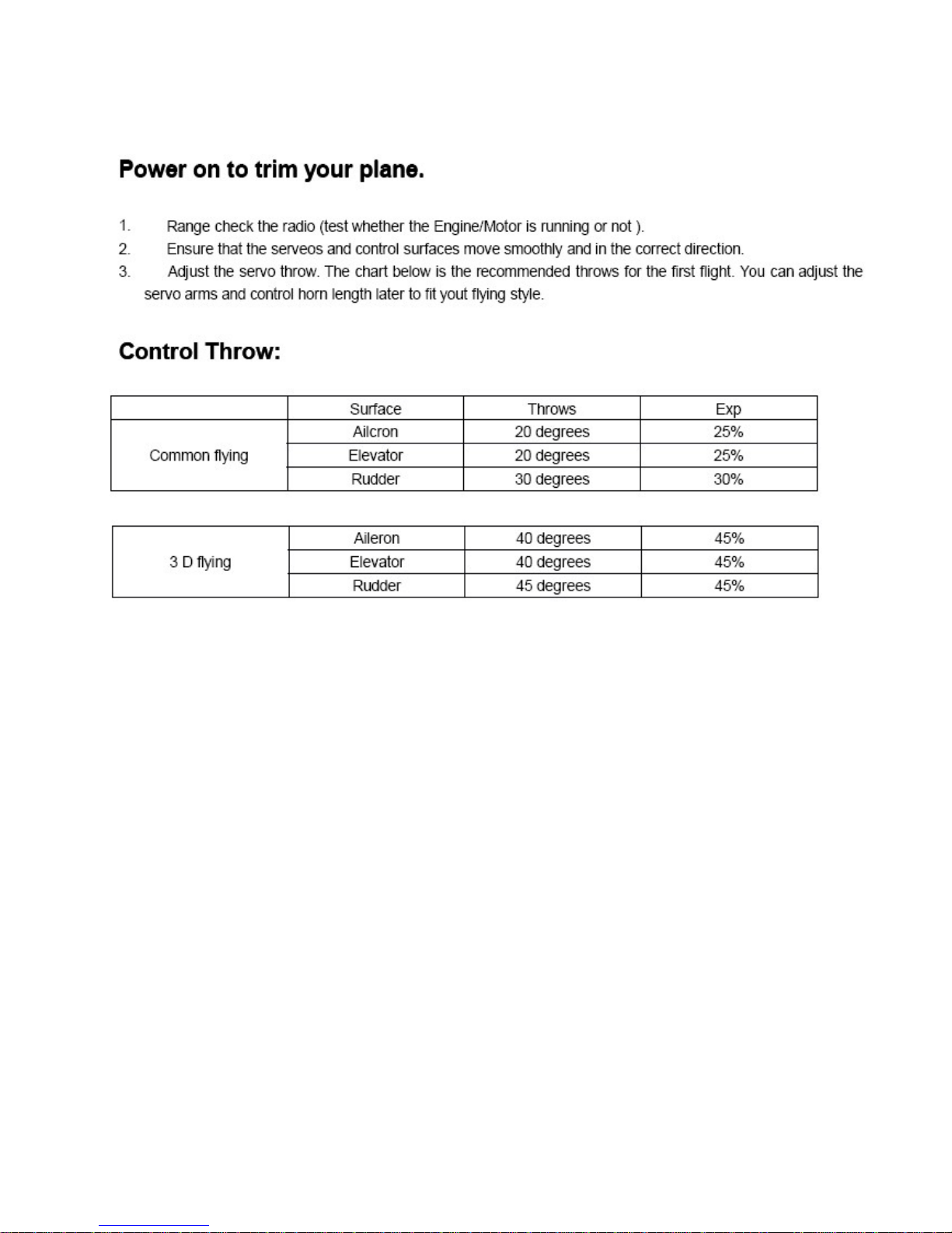
Trail run the Engine to check its stability at high speed and low
speed to ensure there are no problems with vibration on the model.
Run the motor at high speed about 30 min,check the Engine and
make sure the temperature is bleow the prescription of
manufacturer.Once everything is right.
 Loading...