


SECURITY ENCLOSURES
REDWALL® LRP 3020, LRP 4010 and LRP 404 P.I.R. DETECTORS
Installation Instructions
DESCRIPTION
Model LRP3020 is designed to detect human movement within a 30° arc at ranges up to 30 metres (95
feet). See Fig. 2.
Model LRP 4010 is designed to detect human movement within a 10° arc at ranges up to 40 metres (125
feet). See Fig.3.
Model LRP 404 is designed to detect human movement within a 4° arc at ranges up to 40 metres (125
feet). See Fig.4.
All detectors may be used to control floodlighting when combined with INTERSWITCH LRP105.
The rugged cast aluminium housing allows use in heavy industrial environments indoors or out.
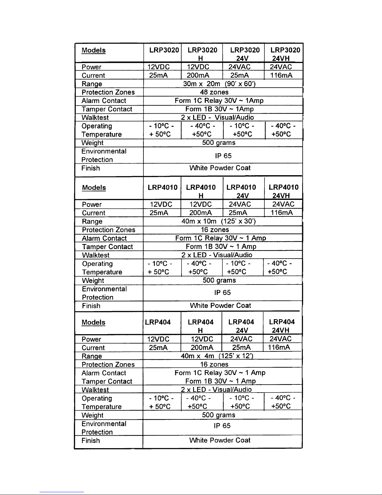
The units require a 12 volt D.C. nominal supply (11v-16v) drawing approx. 25mA (0.025Amp). Models
4010H/3020H/404H have internal heaters and may draw between 25 and 200mA, between +5°C and 40°C. Detection output is by electrically isolated form C (change-over) relay contacts having a 30v 1Amp
max. rating.
The mounting base contains all of the connection terminals. Event indicators, security level selector switch
and jack socket for the audio Walk-Tester LRP 1020. The removable cover is tamper protected by a
normally closed microswitch.
The detector head is factory sealed and has NO user controls or access. The swivel bracket allows 180degree panning and is locked into position by 3 Allen head screws. A matching Allen key is supplied with
every unit and should be retained for future use.
DUAL BI-CHANNEL SYSTEM
All models use four independent element sensors. These, when combined with the optical system,
produce two independent sets of zones ‘A’ & ‘B’ accurately interleaved so that an intruder crossing the
zones will produce sequential ‘A’ ‘B’ ‘A’ ‘B’ signals. Each pair of elements feeds a separate processing
channel (See Fig.1).
Each channel has an LED ‘event’ indicator and memory. This stores the ‘event’ for approx. 10 seconds.
For normal installations, both memories must have ‘events’ stored before the alarm relay is activated. (‘A’
& ‘B’). However, for high security installations, a switch allows the alarm relay to activate if EITHER
memory has logged an ‘event’ (‘A’ OR ‘B’).
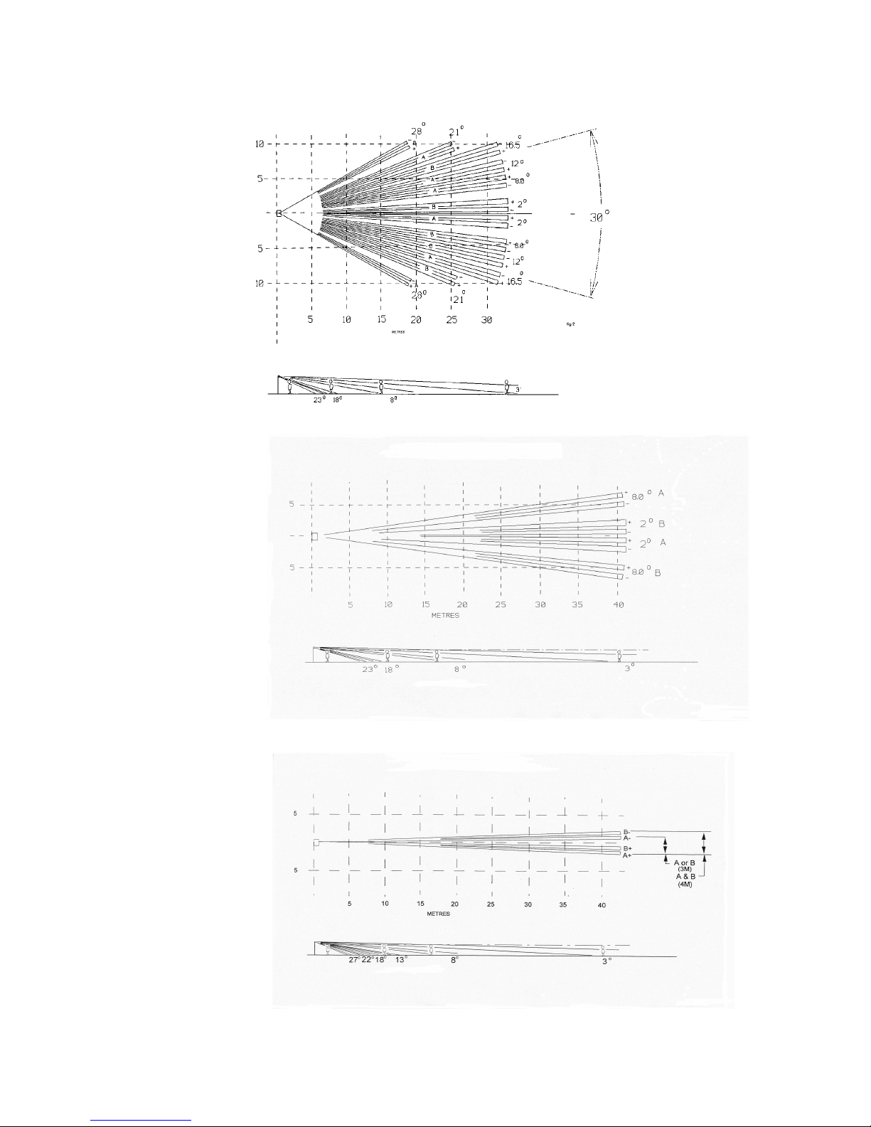
LRP 3020 COVERAGE PATTERN
LRP 4010 COVERAGE PATTERN
LRP 404 COVERAGE

INSTALLATION
When mounted at the recommended height of 2.3m (7’6”) there will be an area directly below the unit
extending to 4m (12 feet) where an intruder may not be detected.
When planning the location, remember that ALL P.I.R. detectors respond best when the
intruder crosses
the zones. Intruders entering a zone from the end and then moving towards the detector may not be
detected for up to 30% of the distance compared to an intruder who crosses the zone.
Fix to a firm rigid surface such as brick or concrete using all four fixing holes and the foam rubber gasket.
ELECTRICAL CONNECTIONS
Fig. 5. Shows the connections for 12 volt D.C. operation
Fig 6 shows connections for 24vac operation
WARNING! DO NOT CONNECT 220/110V SUPPLY VOLTAGES TO
ANY TERMINAL OR PARTS.

For outdoor installation, steel conduit or armoured cable is recommended.
Long cable runs between the power supply and the unit should not result in a total conductor resistance
greater than 20 ohms (10 ohms per conductor). The voltage drop between the power supply and the
detector should not be greater than 0.5Volt. The voltage at the detector terminals should not be less than
11 volts and ideally be higher than 12 volts. For ‘H’ heater models assume 250mA (.25A) for voltage drop
calculations and ensure cables have a resistance, less than 4 ohms (2 ohms per conductor).
If screened cables are used, ensure that the screen is connected to the negative terminal.
NOTE: The metal housing and bracket of the detector is connected to the negative supply terminal, this
means that the power supply negative will be grounded at the detector. In some long distance installations
ground-loop currents may flow if the power supply is also grounded locally.
The ‘&’ ‘OR’ logic selector switch (see Fig.4.) should be set downwards for most installations. This is the
recommended setting for outdoor use, particularly where there may be large animal movements. With this
setting, channel ‘A’ AND ‘B’ must have an ‘event’ within 10 seconds of each other to produce an alarm.
For indoor use, or where the highest security is required, the switch should be moved up. With this setting
an ‘event’ in either ‘A’ OR ‘B’ will trigger an alarm condition.
Double-check all connections before powering the unit.

INITIAL TESTING
With power applied, check that the voltage at the terminal is the correct polarity and is between 11 and 16 volts D.C.
(12 and 16 volts for ‘H’ versions). If an oscilloscope is available, check that the ac ripple does not exceed 0.3V
(300mV) p/p.
During “Warm-up” the alarm relay may switch several times or oscillate for a few seconds.
Allow at least ONE MINUTE before testing.
Set selector switch upwards (A or B).
With NO movement in the area, the walk-test LED's should be out and the alarm relay energised. Movement in front of
the unit should cause the LED's to light and the relay to de-energise. When movements stop, the unit should reset
within 10 seconds.
If audio walk-tester LRP1020 is to be used, insert jack plug into socket on circuit board and set to Redwall position.
With NO movement, the audio tone should be steady. Movement should cause the pitch to vary. There should be a
sudden upward change in pitch when the unit is in alarm condition. When the unit resets the tone should return to the
lower pitch. If the tone does not change, check that the jack plug is fully inserted.
ALIGNMENT
The top surface of the detector head should be used as an initial guide to alignment. The tops of the main upper zones
are parallel with the top surface. If the ground is level the head top surface should be level.
Accurate alignment is essential. Moving the head only one degree will move the end of the detection zone almost one
metre. IF THE UNIT DOES NOT RESPOND TO MOVEMENT AT FULL RANGE, IT IS ALMOST ALWAYS BECAUSE
THE ZONES ARE EITHER AIMING ABOVE THE TARGET OR HITTING THE GROUND TOO SOON.
USING THE AUDIO WALK-TESTER LRP 1020
The LRP 1020 converts the voltage fluctuations at the detector into a changing audio tone. The tone pitch rises and
falls as a zone is crossed. When the unit trips into alarm, the tone pitch suddenly rises in frequency and continues to
fluctuate as the zones are crossed. With a little practice, it soon becomes clear where the zone boundaries and alarm
points are. The LRP 3020,4010 and 404 are effectively two detectors in one housing, alignment and walk-testing are
best carried out with one person walking across the zones whilst another observes the detection LED's and listens to
the LRP 1020 audio walk-tester.
With a two-channel system, it is not practical to feed both movement signals to the audio walk-tester.
The walk-tester jack socket is connected to one channel only, so the audio fluctuations and alarm trip points may
appear to be off-set from the centre line (depending on direction of walk).
When walktesting is completed, double-check the tightness of the terminals and head clamping screw. Check the
tightness of the main fixing screws, (it is essential that the unit is firmly mounted and unlikely to move or vibrate in
windy conditions). Check cable gland is tightly fitted and that the rubber grommet grips the cable firmly. Re-set switch
to ‘A’ and ‘B’ (downwards) position.
Remember, both channels must be activated within a ten-second period to produce an alarm condition when the switch
is in the downward position.
In some countries where excessive climatic variations are expected, installers should provide additional protection to
the unit by means of the sun or snow shield accessories.
SEALING
Although the component boards are protective coated, it is recommended that the terminal and wiring are lightly coated
with a silicone water-resistant spray. Re-fitting the cover base cover should operate the tamper switch.
DO NOT SPRAY SEALANT ON TO DETECTOR HEAD FRONT WINDOW OR USE SILICONE SEALANT
TO SEAL THE CONNECTION ENCLOSURE.

MAINTENANCE
In addition to regular ‘walk-tests’, periodically check that the unit is still firmly fixed to the mounting surface.
Check the front of the detector head for build up of dust, sand. animal or insect debris and carefully remove
by vacuum or blowing. Avoid touching or scraping the front window material. The frequency of these
checks will depend on the environment and location conditions. They should be carried out not less than
twice per year. Remove the terminal cover and check for ingress of water, insects, fungus and corrosion.
The detector head is factory sealed and no attempt should be made to open it.
PERFORMANCE CONSIDERATIONS
All P.I.R. detectors will exhibit changes in ultimate detection range. When an intruder moves across a zone
he causes a change in the received infrared heat energy. If the temperature difference is large, i.e. cold
background, warm intruder, the change of energy and therefore alarm signal, is large. Conversely, a wellcovered intruder against a hot background will produce a small signal. The effect is that the actual final
detection point will vary due to variations in background temperature, intruder size and clothing and speed
and direction of motion. The LRP 3020 is designed and tested to operate at 30 metres nominal, the LRP
4010 and LRP 404 is tested to 40 metres nominal. In some conditions the range may exceed these
distances, in other conditions (typically very hot) the ultimate range may be reduced.
UNW AN TED ALARMS
The LRP 3020/4010 and 404 detectors are designed to ignore a wide range of hazards that can effect P.I.R
detectors when located outdoors. The heavy metal casing resists sudden temperature changes. The light
paint colour keeps internal temperatures low and the comprehensive sealing ensures a draught free
environment for the precision temperature sensors. The most likely cause of unwanted alarms will usually
be within the protective zones. Animals such as a dog, fox, or deer are likely to be detected. Smaller
animals such as rabbits or cats are unlikely to cause problems because they produce a relatively small
thermal image. Other common hazards may be movement of foliage within the zones and unstable
mounting surfaces.
DIMENSIONS

ACCESS0RIES
LRP105 Mains power supply with light sensor and timer for switching mains loads up to 1200 watts
incandescent (600watt, 110 volt models).
LRP 1020 Audio Walk Tester
The REDWALL® LRP 3020, 4010 and LRP404 are part of a range of security products including:
REDWALL®100Q 100m x 3m long range detector
MEGARED®180Q 180m x 4m ‘Super’ long range detector
REDWIDE®5030 50m x 30m wide angle detector
REDWATCH®100Q Detector and camera combination
REDWATCH®5030 Detector and camera combination
REDNET® Active infrared beam systems
VIDESWITCH Two way remote switching system using CCTV coax cable.
These units are designed to detect intrusion and initiate a signal to control equipment. They are NOT a
burglar/theft prevention device and we cannot accept responsibility for any losses, should they occur.
 Loading...