

Red Valve WATERFLEX SERIES WF-3 Installation, Operation And Maintenance Manual

The revolutionary design of the Series WF-3 InLine
Check V alve provides reliable backflow prevention.
The valve solely operates on differential pressure
and has no moving mechanical parts. The valve
exhibits low headloss, high backpressure ratings and
a short face-to-face dimension.
The valve is only intended for clean flow media or
media with only fine particulates.
The Series WF-3 is constructed with ANSI, DIN, BS
or special flange drillings for easy installation.
IMPORTANT
Please take a moment to review this manual. Before performing any maintenance on the
valve be sure the pipeline has been de-pressurized. The improper installation or use of this
product may result in personal injury, product failure, or reduced product life. Red Valve Co., Inc.
can accept NO liability resulting from the improper use or installation of this product. If you have
any questions or problems, please call the customer service department at (412) 279-0044. We
appreciate your comments. And thank you for choosing Red Valve.
WATERFLEX SERIES WF-3
INSTALLATION, OPERATION, AND MAINTENANCE MANUAL
™
Flow
Flow
2
1. PIPE AND INSPECTION OF VALVE:
Check flange faces of pipe for rough/damaged
areas. Pipeline flanges must be flat, properly spaced,
and parallel to achieve proper seal. PVC flanges may
not seal properly, and are not recommended by Red
Valve. If PVC flanges are used, metal back up rings
should be placed behind the PVC flanges in order to
prevent yielding. Grind or file any sharp edges of pipe
flanges to prevent damage to the gaskets.
2. GASKETS:
Two flange gaskets by others are required, one on
each side of the disc. (See Figure 2.)
3. INSTALLING FLANGE BOLTS:
Tighten all bolts uniformly to distribute pressure
evenly around the sleeve flange. (For bolting sequence refer to the back page of this IOM).
4. VALVE ORIENTATION:
The membrane must be on the downstream side of
the disc when properly installed in a pipe line.
(See Figure 2.)
Make sure membrane is concentric with pipe I.D.
When installed in a horizontal pipeline, the rod must
be in the vertical position. (See Figure 3.)
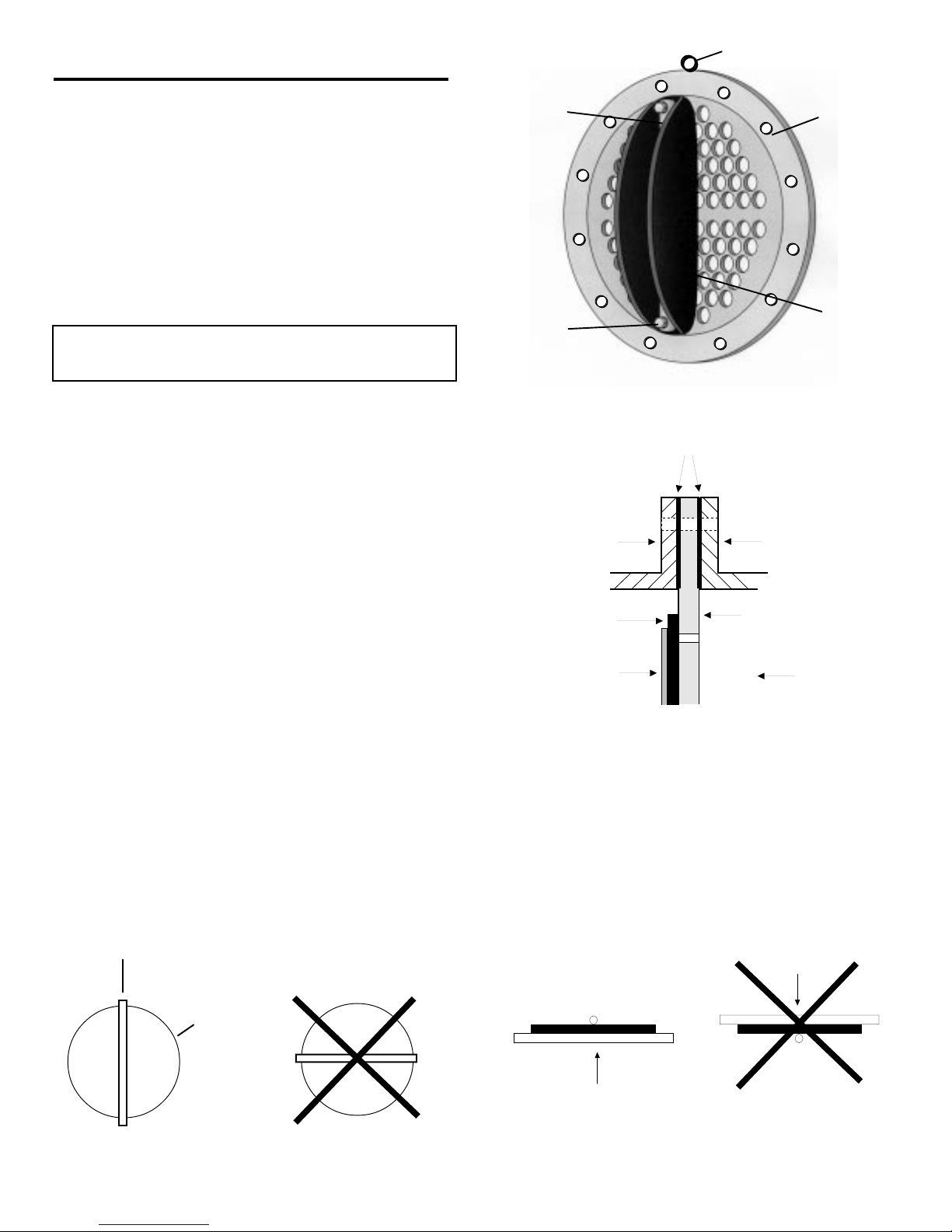
GENERAL DESCRIPTION
Terms used in this I.O.M. to refer to various parts of the
valve are described below.
(See Figure 1.)
1.
Disc
2.
Membrane
3.
Mounting Rod
4.
Rod Fasteners with Lock Nuts
5.
Lifting Eye (sizes 10" and up)
INSTALLATION
It is acceptable to install the valve in a vertical pipeline
provided normal flow direction is bottom to top.
(See Figure 4.)
It is not recommended to install the valve in a vertical
pipeline where the flow direction is from top to bottom. The membrane may tend to come away from the
disc and may not seal with minimal backpressure.
(See Figure 4.)
1
2
3
5
4
(Figure 1)
(Figure 2)
Flow
WF3 Disc
Pipe Flange
Pipe Flange
Gaskets
Membrane
Mounting Rod
Mounting Rod
Membrane
(Figure 3)
(Figure 4)
 Loading...