

Red Valve Flexgate D series Installation, Operation And Maintenance Manual
IMPORTANT
Please take a moment to review this manual. Before performing any maintenance on the
valve be sure the pipeline has been de-pressurized. The improper installation or use of this
product may result in personal injury, product failure, or reduced product life. Red Valve Company,
Inc. can accept NO liability resulting from the improper use or installation of this product. If you
have any questions or problems, please call the customer service department at (412) 279-0044.
We appreciate your comments. Thank you for choosing Red Valve.
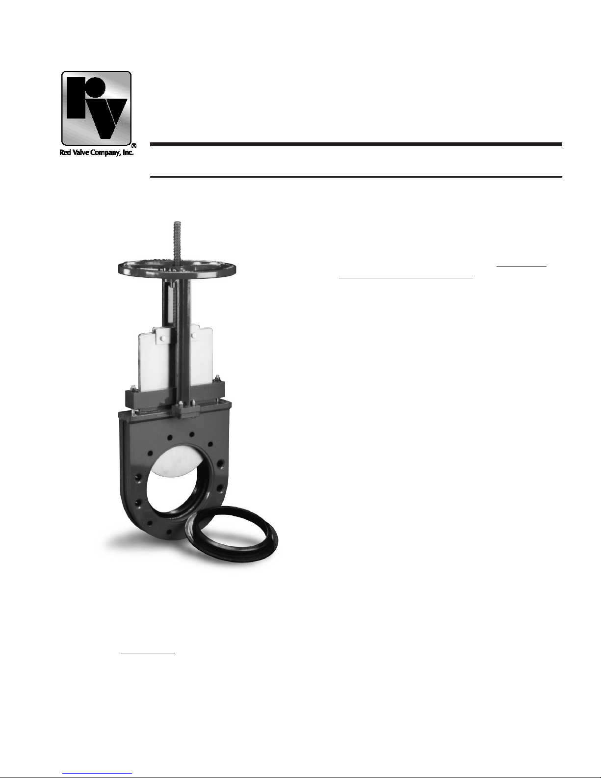
The Red Valve Series D Flexgate Slurry
Knife Gate Valve is a 100% full bore, truly
bi-directional valve designed for tough slurry
applications. The Flexgate features heavyduty elastomer seat cartridges which provide
droptight closure and are replaced WITHOUT
ANY VALVE DISASSEMBLY, for ease of
maintenance.
The Series D Flexgate is designed to meet
MSS-SP81 face-to-face dimensions, so that
it can be readily placed in service replacing
conventional knife-gate products.
Flush ports are provided to allow the valve to
be ushed with water and/or air. With a variety
of actuators available, limit switches, and other
options, the Red Valve Series D Flexgate can
be built to t your special applications.
SERIES D FLEXGATE
SLURRY KNIFE GATE VALVE
Installation, Operation and Maintenance Manual

INSTALLATION
NEVER...
Use bolts which bottom out in body.
NEVER...
Install with gate up.
DO...
Lubricate seats and gate.
DO...
Use at-faced falnges and ighten bolts evenly.
1. When your Red Valve order arrives, check the contents
carefully to assure no damage or loss occured in transit.
2. Check ange faces of pipe for rough /damaged areas. Pipe-
line anges must be at, properly spaced, and parallel to
achieve proper seal. DO NOT mate Flexgate valves directly
to expansion joints or other exible connections. The ID of
the mating pipe ange must not exceed the nominal steel
pipe OD by .12" for sizes 12" and smaller, or .25" for sizes
14" and larger. Consult Red Valve if the ange ID exceeds
these dimensions. Std slip-on steel anges meet the criteria.
Slip-on adaptor anges for ductile iron pipe can create a
sealing problem.
The Flexgate can be used for end of line service if a at
face ange is bolted to the downstream side so that the
downstream seat is retained. When the Flexgate is used to
isolate equipment for future removal from the line, a spool
piece needs to be installed between the valve and equipment if the end of line condition will result upon removal of
the equipment.
3. The rubber seat acts as a gasket and separate ange
gaskets are normally not required. Installations where the
mating ange has a "slick" surface may require a metal
serrated or combination metal gasket serrated gasket and
contractor supplied standard gasket materials to assist in
creating a seal. All gaskets used on "LOW TORQUE" ange
material such as FRP and PVC should be approved by the
pipe manufacturer for compatibility. (Often the torque rat-
ing of the composite mating ange may be less than the
minimum torque required to install the valve
4. Actuate valve to the full CLOSED position for installation.
Lubricate seat cartridges and gate liberally with a grease
compatible with the seat material. Red Grease is recommended for all seat materials.
5. Insert seat cartridges. Flange gaskets are not required.
Make sure that cartridges are of the correct size and prop-
erly centered on valve ange.
6. Installing Flange Bolts:
CAUTION: Only use ange bolts of the correct length in
such manner that the BOLTS CAN NOT BOTTOM OUT
IN TAPPED HOLES. The use of bolts which are too long
and bottom out in tapped holes can distort body, create a
leak path and cause permanent valve damage. Red Valve
recommends the use of studs in the chest area of the
Flexgate in lieu of bolts.
Tighten each bolt uniformly on both sides of
the valve (upstream and downstream side of
the valve). This will distribute compression
evenly on seat ring. Torque all the ange
bolts and/or studs in a star pattern (as shown
in Figure 1), rst to 50% of tabulated values,
then retorque to 100% of 100% of tabulated
values. If greater torque is required, continue retorquing in
increments of 50% of tabulated values. Improper or uneven
torquing of ange bolts can cause premature seat cartridge
failure and a leak between the mating ange and valve. Use
of high quality anti-sieze compound on all bolt and/or stud
thread is recommended.
7. Apply grease liberally to stem. Red Grease from Red Valve
is the recommended lubricant for the stem and seats and
is available by contacting customer service at Red Valve.
8. Some leakage may occur at packing when line is pressur-
ized. The factory does not tighten packing to overcome
such leakage, as this can shorten packing life when valve
is in storage. Simply tighten the packing nuts until the leakage ends.
9. Over tightening ange bolts to stop a leak can fracture or
distort a composite ange such as a FRP or PVC ange.
Steel back-up rings should be considered to try to seal a
ange against a leak. Caution should be used to not overtorque FRP or PVC anges when using steel back-up rings.
Consult with the pipe and/or ange manufacturer.
10. Fill out and attach the enclosed VALVE MAINTENANCE
CARD to the valve. This has been provided for maintenance
convenience.
CAUTION: VALVES EQUIPPED WITH THE FLUSHPORT
DESIGN CAN BE PLUGGED OR PIPED TO A SUITABLE
DRAIN. REMOVAL OF PLUG(S) WILL CAUSE LEAKAGE OF LINE MATERIALS. CONSULT YOUR SYSTEMS
ENGINEER FOR PROPER PLUMBING OF FLUSHPORT
FOR YOUR INSTALLATION.
NOTE: It is recommended that valves with actuators be
installed in the vertical position. If actuated knife gates
must be installed horizontally, it is recommended that the
actuator be supported with a hanger or bracket.
1
2
3
4
5
6
78
Figure 1
 Loading...