


LaGG-3
Instruction Manual
Wingspan: 66 in. (1676 mm.)
Wing Area: 980 sq. in. (63.23 dm
2
)
Weight: 9.5 – 10.5 lbs (4082g – 4536 g)
Length: 59 in. (1473 mm.)
Wing Loading: 22- 24.5 oz per sq ft
(64.6-71.8 g per dm
2
)
308 Belltown Road, Owings Mills, MD 21117-3239
www.redstarrc.com
red_star_rc@yahoo.com

© 2006 Red Star RC
2
Thank you for purchasing Red Star RC LaGG-3 sport scale model Kit. This k it h as been designed using 3D
computer engineering and inte rloc king construction design help you to build straight lightweight model. Low
wing loading and built in washout make this model a good flying plane. Please keep in mind that this kit is
intended for intermediate builder and intermediate pilot. If you do not meet these criteria, it is recommended to
seek help from a more experienced builder / pilot.
Good luck!
Mike & George.
Red Star RC, BALTIMORE, MARYLAND, USA
redstarrc@yahoo.com
WARRANTY…..Red Star RC guarantees this kit to be free from defects in both material and
workmanship at the date of purchase. This warranty does not cover any component parts damaged by use or
modification. In no case shall Red Star RC’s liability exceed the original cost o f the purchased k it. Further, Red
Star RC reserves the right to change or modify this warranty without notice.
In that Red Star RC has no control over the final assembly or material used for final assembly, no liability shall
be assumed nor accepted for any damage resulting from the use by the user of the final user-assembled product.
By the act of using the user–assembled product, the user accepts all resulting liability.
If the buyer is not prepared to accept the liability associated with the use of thi s product, the buyer is advised to
return this kit immediately in new and unused condition to the place of purchase.
Our deep appreciation to Bennie Broughton aka Oryx on www.rcscalebuilder.com
for his time and
efforts he spent for deep aerodynamic analysis and recommendations for wing airfoil.
NOTES BEFORE BEGINNING CONSTRUCTION
• Read the instructions and the plan sheet prior to start any work.
• Do not remove the parts from sheets until required.
• Prior to gluing, test fit and match parts over the plan.
Kit Contents:
• Computer Drawn Plan Sheets 2
• Illustrated Instruction Manual 1
• Laser Cut Balsa and Plywood Parts Sheet 30
• Clear Canopy 1
• Fiberglass cowl 1

© 2006 Red Star RC
3
Additional Hardware (Required for completing kit):
6-32 Bolt-nut Set (4 bolts, 4 Flat Washers, 4 Lock Washers, 4 Blind Nuts) 1
Push rod (Du-Bro #230) Ailerons 1
E/Z Links (Du-Bro #855) Ailerons 1
E/Z Connectors (Du-Bro #121) 1
Push Rods Sullivan Gold-n-Rod 1
Mechanical Retracts .60 - .90 size 85
degrees 1
Du-Bro Nylon Large Straps 5/32"(4) Landing Gear Covers 1
Wheel Axels 2
Wheel Collars 2
Wheels 4” 2
Robart 121 Scale Retractable Tail wheel 1
Tail Wheel 1.75” 1
Fuel Tank 12 oz 1
Spinner 4.25”
(Dave Brown Vortech Standard S242-8242 & XX-long adapter nut) 1
Engine OS-.91FX 1
Muffler 1
Prop Master Airscrew 14x6 1
Robart 3/16" Super Point Hinges 23
Recommended Finishing Items:
MonoKote (Sky Blue 20206) 2
MonoKote (Gray/Green 20211/20214) 2
LustreKote Spray Paint 2
LustreKote Spray Flat Clear 2
Radio Gear:
7-channels receiver (9-channels recommended) 1
6” Servo Extension 2
12” Servo Extension 2
6” Y-servo Extensions 1
Standard Servos 8
Items You May Need:
Thin and Medium CA
30-min Epoxy
Wax Paper or Plastic Wrap
Razor Blades
Different Grid Sand Paper
Balsa Wood Filler
Windex
Isopropyl Alcohol

© 2006 Red Star RC
4
Build the Stab & Elevator
Unroll the plan sheets. Put them on your building
board and cover with wax paper so glue will not
adhere.
1. Locate and carefully remove Elevator parts from
balsa sheets. Test fit and sand them if necessary.
Assemble using plan as a reference.
2. Glue precut leading edge ELE.
3. Glue precut tips EET and end blocks EEB.
4. Glue balsa reinforcing edges a n d san d to shape.
Glue precut hinge blocks EHB.
5. Shape leading edge round.
6. Put stab ribs over the plan and fi x th em into
position.

© 2006 Red Star RC
5
7. Glue central forward ply horizontal reinforcing
stringer, rear reinforcing stringer, subleadning
edges. Glue subtrailing edge and subtrailing edge
doubler. Lightly sand it to prepare for sheeting.
8. Glue hinge blocks according to the plan using
balsa leftovers. Prepare sheeting by gluing three
1/16”x4”x19.5” sheets together along longer side.
Then cut it by half. Sheet top of the stub. Remove
from building board and sheet bottom.
9. Glue precut stub tips HST together.
10. Glue tips to the stub. Glue centering piece HSCP in front of the stab.
11. Glue precut leading edges HS-LE to the
stub.
Build the Fin & Rudder
1. Glue two rudder halves RF1-1 and RF1-2
together.

© 2006 Red Star RC
6
2. Glue two leading edges RLE together. G l ue
ribs and resulting leading edge to rudder core.
3. Glue rudder bottom tips RBT together by pairs
and glue them in place in the bottom of the rudder.
3. Glue hinge blocks and control horn support
block from balsa leftovers according to the plan.
Make sure they are lower than ribs.
4. Shape leading edge round.
5. Glue ribs VS1-1(goes up top) and VS1-2
together. Pla ce Ve rtical stab ribs over the plan. Glue
subleading VSSLE and subtrailing VSSTE edges.
6. Sheet top of the stab. Remove it from building
board.

© 2006 Red Star RC
7
7. Glue hinge block and shap e i t.
8. Sheet Vertical stab from the other side. Glue
together two halves of stab tip VST and glue tip
in place.
Build the fuselage
1. Locate and assemble top fuse formers.
Attention! All formers installed with markings
facing forward (toward nose).
2. Locate and assemble nose parts. Gl ue
stringers together according to the plan.
3. Assemble fuse nose part over the pla n.
4. Glue two 1/8x1/4x24” side bass stringers
together. Make two of them

© 2006 Red Star RC
8
5. Put them over the plan and form using t-pins.
Join them with nos e pa rt.
6. Glue top formers according to the plan.
Control ve r t i ca l us ing square.
7. Install horizontal stab saddle SS. Install top
horizontal substringer FT1. Install stringers.
8. Glue sheeting support do ublers SSD. Install
vertical stab.
9. Install canopy rear window former W.
10. Shape top substringer.
© 2006 Red Star RC
9
11. Sheet the fuselage with 1/16” balsa sheets. Do
not sheet tail yet. We need an access to the pushrods
installation.
12. Glue precut top stringer FT-2. Now it’s time to
remove fuselage from the building board.
13. Build the motor box. Make sure everything
strait and true. Fuelproof forward part from the
outside using 30 min epoxy tinned with isopropyl
alcohol. It will be hard to access it once installed in
the fuselage.
14. Glue two firewall 1/8” light ply and one 1/16”
burch ply formers. Attach motor mount aligning it
using the reference lines.
15. Install blind nuts and secure them with CA.
16. Glue reinforcing triangles and install firewall
using 30 min. epoxy.

© 2006 Red Star RC
10
17. Build retractable tail wheel former from F19-B,
F20 and two TW’s.
18. Glue servo tray doublers F-STD to servo
tray F-ST. Install servo tray into the fuselage.
19. Install motor box and remaining formers in th e
fuselage. When installing former F21 you may need
to unglue two side bass stringers from the last
former VSSTE-T. Install Wing Support formers
WS1 and WS2.
20. Install remaining stringe rs according to the plan.
21. Install wing support plate WSP and bolts
doublers WSP-D underneath the plate.
22. Install two rudder hinge blocks using balsa
leftovers.

© 2006 Red Star RC
11
23. Install pushrods according to the plan and glue
them to the formers.
24. Build the fuselage part of a ir scoop from former
AS4 and stringers ASS-2 and ASS-3.
25. Glue precut sheeting support WSS to wing
saddle doublers and sand them into shape.
.
26. Sheet bottom of the fuselage except tail.
27. Install retractable tail wheel. Connect pull-pull
cable. Sheet tail part of the fuselage.
28. Install pushrod support from both ends from
balsa leftovers.
© 2006 Red Star RC
12
29. Install push rod end blocks from both sides.
30. Make elevator joint according to the plan from
3/32” rod.
31. Drill elevator halves according to the plan and
test fit joint. Hinge elevator and horizontal stab.
32. Install pushrod with precut supported former
EPSS.
33. Install horizontal stab. Glue sheeting support
from both sides.
34. Sheet top. Glue precut vertical stab leading
edge. Glue balsa block from balsa leftovers between
vertical stab and top to form fairing later.

© 2006 Red Star RC
13
35. Sand fuselage to shape.
36. Glue tail block and sand it to shape. Glue
vertical stab doubler VSTE.
37. Hinge rudder and install precut control horn.
38. Glue small triangle from balsa leftover to
horizontal s tab and sand it to shape. Do th e same for
another side.
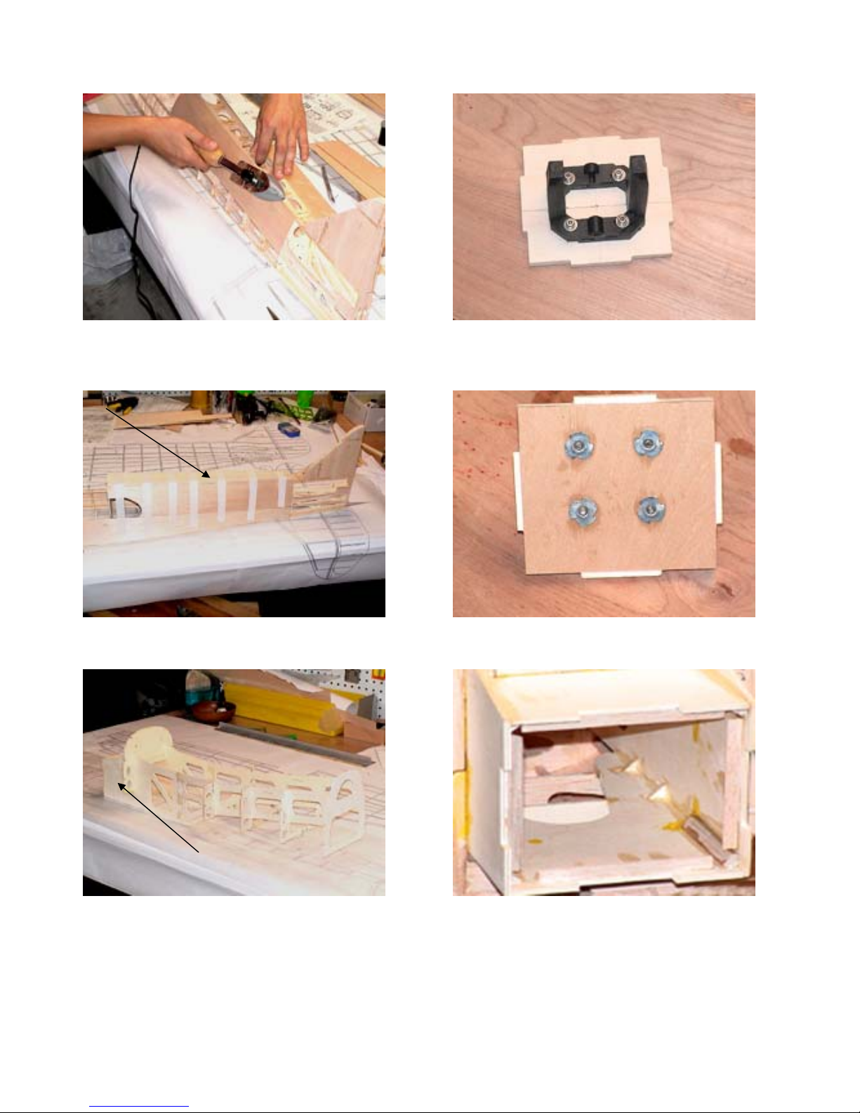
Build the Ailerons
1. Glue two aileron tips together.
2. Glue ribs according to the plans. Glue aileron
tips. Double tip goes to the bottom. Remember that
the other aileron is a mirror copy of this one. Do not
build two identical ailerons!!!
© 2006 Red Star RC
14
3. Glue 1/8” end doublers AR-1D a n d AL-1D.
4. Glue precut leading edge.
5. Glue precut 1/4” balsa hinge blocks (by pairs
from each side). Make sure they are lower than ribs.
Sand them if necessary. Do not round leading edge
yet.
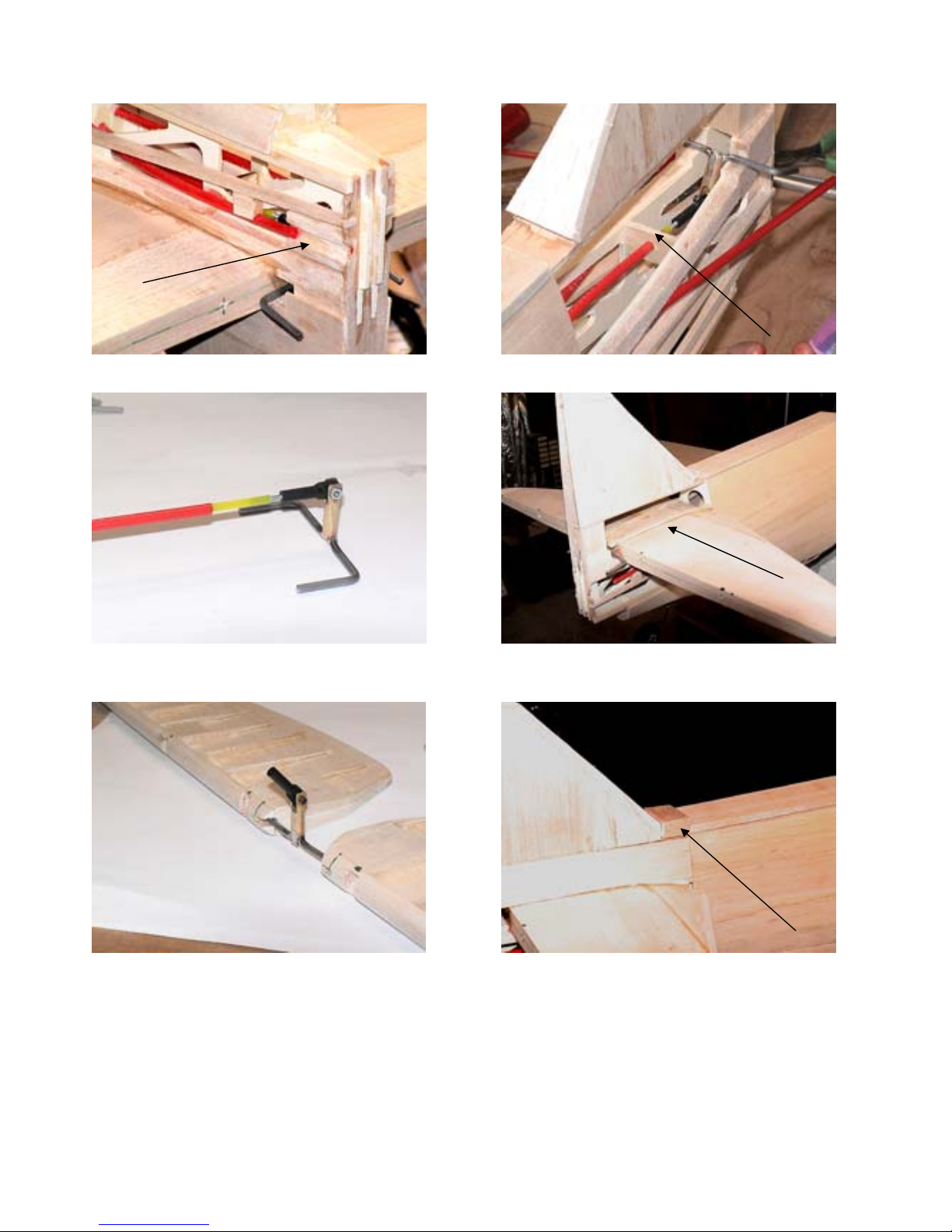
Build the Wing
1. Glue wing rib doublers with 30min epoxy. Pay
attention on left/right position of the doublers!
2. Glue landing gears former doublers with 30min
epoxy.
3. Make landing gear assembly with 30min epoxy.

© 2006 Red Star RC
15
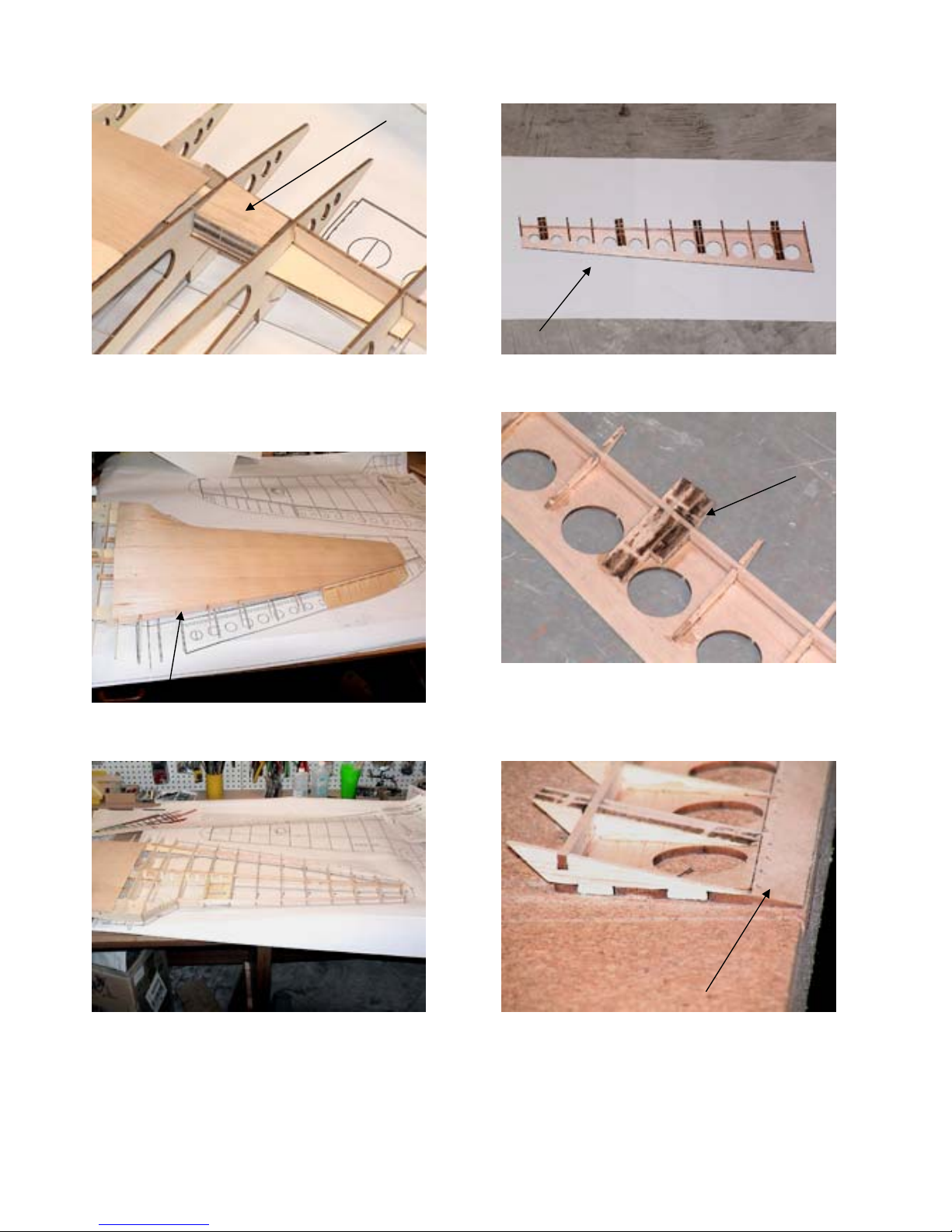
4. Cut 1/2”x 1/4” central wing sect io n bass stringers
according to the picture (6.5” and 2.5”).
They will
also be a retract servo tray.
5. Glue Top and Bottom wing bolt support blocks
WBB. Top – WBB-1, WBB-2, WBB-3. Bottom –
WBB-1, WBB-2, WBB-3, WBB-4
6. Glue central rib doublers R1-D. Make right and
left of them.
7. Glue flap servo doublers WFSD. They go on
the opposite side than R4-B doubler! Make right
and left ribs!
8. Glue aileron rib doubler. Make right and left
of them!
9. Assemble central wing section accordin g to t h e
plan.

© 2006 Red Star RC
16
10. Assemble subleading edge from WSLE-1 &
WSLE-2
11. Assemble right wing on building board
according to the plan. Glue aileron doubler.
12. Note flap and aileron trailing edge joint.
13. Sand the wing preparing it for sheeting.
14. Install shear web from 3/32 (1/16) leftovers. The
last one goes from the other side in order that not to
interfere with servo tray.
15. Prepare four sheathings from 1/16” balsa sheets
according to the templates provided.
© 2006 Red Star RC
17
16. Install top Wing Bolt Support Block WB B
and sand it to shape.
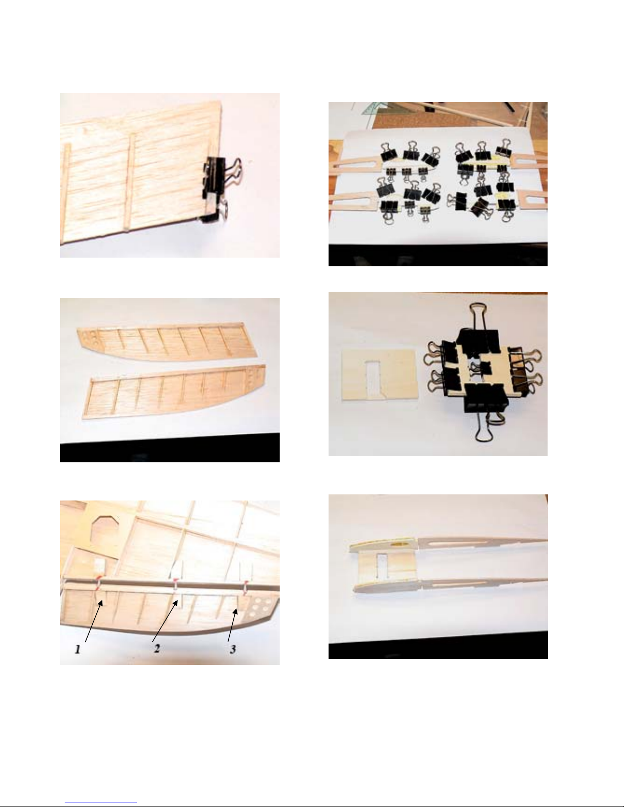
17. Sheet top of the wing. Live a space for flap
sheeting on trailing edge
18. Build and sheet left wing the same way you
built the right one
19. Put flap base on building board. Glue ribs
according to the plan.
20. Glue additional R8 doubler on place according
to the plan (goes from the narrow side!). Remember
to build right and left flaps!
21. Sand the edge of the flap at the rib angle

© 2006 Red Star RC
18
22. Sheet flap leading edge and top. Sand to shape.
23. Mount flap servos.
24. Glue balsa 1/4” leftovers to flap an d aile ron
servo cover bases.
25. Glue them in place.
26. Build wheel well from 1/16” balsa leftovers
and send them to shape.
27. Glue Landing gear shim from ply leftovers,
sheeting support around from balsa and sand to
shape.

© 2006 Red Star RC
19
28. Install retract servo, pushrods, retracts and
test them for smooth operation.
29. Install hinge blocks according to the plan.
30. Mark hinge location and then hinge flaps.
31. Glue precut control horn in place.
32. Connect pushrod to test fit flap function.
33. Prepare wing flap top sheeting from precut
1/16” balsa sheet and 1” wide strip sandwich from
1/32” balsa and 1/32” ply according to the templates
provided.

© 2006 Red Star RC
20
34. Sheet top of the wing flap area with ply
reinforcing strip facing inside out.
35. Glue bottom wing bolt support blocks and
sand them to shape.
36. Make four servo mounting blocks. Glue support
blocks to servo covers and mount servos.
37. Sand the wing and sheet wing bottom. Cut
servo openings.
38. Cut landing gear openings.
39. Cut central section of trailing edge according to
the plan. Install central section trailing edge
sheeting support blocks from 1/4” and 1/8” balsa
leftovers, shape them and sheet the central section.

© 2006 Red Star RC
21
40. Glue 1/8” balsa strip alongside flap trailing edge
and sand it flash with flap.
41. Cut pre-marked leading edges from
3/4x3x36 balsa sheet. Glue them to the wing
42. Pin ailerons to the wing. Make sure they in the
right place (left and right). Cut and glue wing tips.
43. Glue forward side leading edge from leftovers
3/4x3x36 balsa sheet. Install wing dowels. Shape
leading edge and wing tips according to the plan.
Then round ailerons leading edges and hing e the m.
44.
Drill two holes and tap them 1/4x20. Sharp two plastic
bolts and screw them in that sharp ends will come out about
1/4”. Place the wing onto saddle and align the way that
distance between wingtips and tail equal. When satisfied push
the wing down to mark holes location. Drill holes 1/4” dia.
45. Cut sheeting around holes and glue light ply bolt
support pieces.

© 2006 Red Star RC
22
46. Build wing air scoop from formers AS1-AS3,
stringers ASS-1 and . Glue sheeting support blocks
around wing bolts.
47. Sheet air scoop. Cut sheeting around wing bolts.
48. Build forward wing fairing.
49. Sheet forward fairing and cut openings for
landing gear.
Install the Fuselage components
1. Glue fairings. Fill the space with balsa and
shape. Cut machine gun blisters and shape them
to fit. Trim and fit canopy and rear windows.
2. Install machine guns from 1/16” tube and
cannons from 1/4” tube sizes.

© 2006 Red Star RC
23
3. Install servos into servo tray, mount hardware.
4. Glue cowl support blocks from balsa leftovers.
5. Test fit cowl. Drill holes, temporary screw in.
Remove it and put a drop of thin CA in balsa
blocks.
6. Glue together plastic exhaust pipes.
7. Glue them in place. Add panel lines and rivets
from aluminum foil self-adhesive tape.
8. Install throttle servo and pushrod supporting
block.

© 2006 Red Star RC
24
9. Install Fuel tank and secure it with balsa block at
the back and foam around. Battery pack strapped to
the fuselage structure here to achieve proper
balance. Your battery location may be different.
10. Fuel lines goes inside motor mount.
11. Throttle pushrod needs to be bent to reach
carburetor arm.
12. We are using custom in cowl muffler.
Prepare the Model for
Covering
1. Inspect all surfaces for uneven glue joints and
seams that require filler. Apply fi ller where needed.
Many small dents or scratches can be repaired by
applying a few drops of water or moistening the
area with a wet tissue. This will swell the wood,
allowing you to sand it smooth after the balsa wood
has dried.
2. Sand the entire model with progressively finer
grits of sandpaper, finishing with 320 or 400-grit
sandpaper.
3. Use a Tack Cloth to remove sanding dust from
the model.
Balance the Model Laterally
1. Mount your wing to the fuselage. Temporarily
install flaps, ailerons, rudder, elevator, landing
gears, engine with prop and cowl.
2. With the wing level, carefully lift the model by
the engine propeller shaft and the aft end of the
fuselage at the bottom of the fin trailing edge (this
may require two people). Do this several times.
3. If one wing always drops when you lift the
model, that side is heavy. Balance the airplane by
gluing weight inside the other wing tip. Glue the
weight in place with epoxy. An airplane that has
been balanced laterally will track better in loops and
other maneuvers.
4. Remove all the part previous ly installed.

© 2006 Red Star RC
25
Cover the model
We won’t go into many details on covering
techniques, assuming that you have already covered
a couple of models in the past.
We fiberglass our model and painted it with acrylic
paint. Markings were painted over templates we
made.
Cockpit
1. Cut the picture. Paint front panels gray.
2. Glue picture on the base, cower with t hi n c lear
plastic and glue painted front pa ne l up top. Make
switches from soft wire required diameter.
3. Site made from balsa leftovers and painted.
4. Stick made from balsa leftovers.
5. Pilot’s seat made from balsa leftovers and
painted. All cockpit d etails glued in place.

© 2006 Red Star RC
26
Final assembly
• Reassemble all the hardware and make final check
on all components. Permanently hinge all control
surfaces.
• Glue canopy in place
• Check radio operation and control throws (first
number is for low rates)
• Ailerons: 1/4” to 1/2 UP and DOWN
• Elevator: 1/2” to 1” UP and DOWN
• Rudder: 1/2” to 1” LEFT and RIGHT
• Throttle: Full range of throttle.
• CHECK BALANCE AS PER PLANS.
Landing Gear Cover
We made landing gear covers from thin aluminum
sheet and screwed them in with
Du-Bro Nylon
Large Straps 5/32"
PRE-FLIGHT CHECKOUT
• Make sure the servos are securely mounted
and that the servo arms have their retaining screws
in place.
• It is also a good idea to re-check all the
push-rod connectors, fuel tank moun ting, fuel lines,
wheels; engine mounting, prop and spinner.
• Range check the radio as per the
manufacturer’s instructions and make sure it is fully
charged.
DOUBLE CHECK EVERYTHING
YOU CAN THINK OF!
A model and radio that is not prepared and w orking
properly on the ground before take off will not
improve in the air IT WILL GET WORSE! There is
no point in attempting to fly until everything is
100% correct.
Please let us know what we
could do to make this kit better!
308 Belltown Road, Owings Mills, MD 21117-3239
www.redstarrc.com
red_star_rc@yaho.com

© 2006 Red Star RC
27
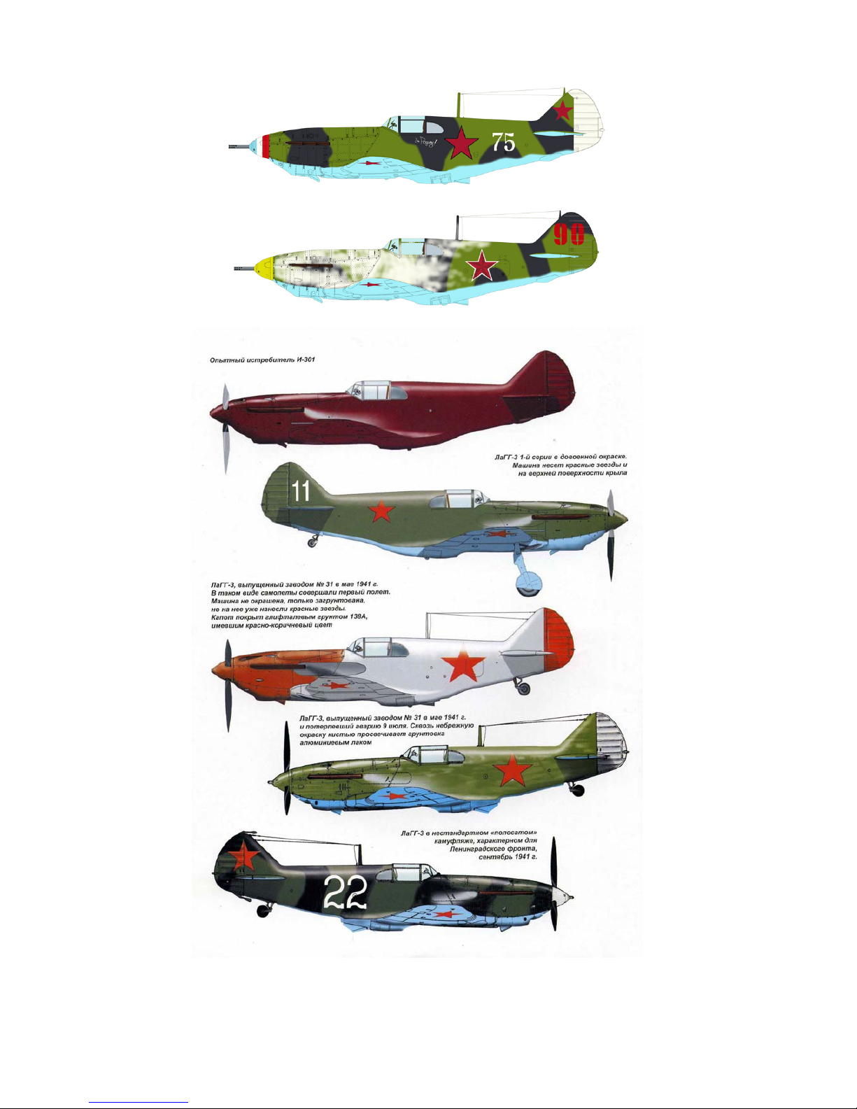
LaGG-3 Paint scheme (from Squadron LaGG fighters in action)
© 2006 Red Star RC
28

© 2006 Red Star RC
29

© 2006 Red Star RC
30
 Loading...