

Red Sound Systems MicroSYNC Owner's Manual
INPUT
www.redsound.com
POWER
13
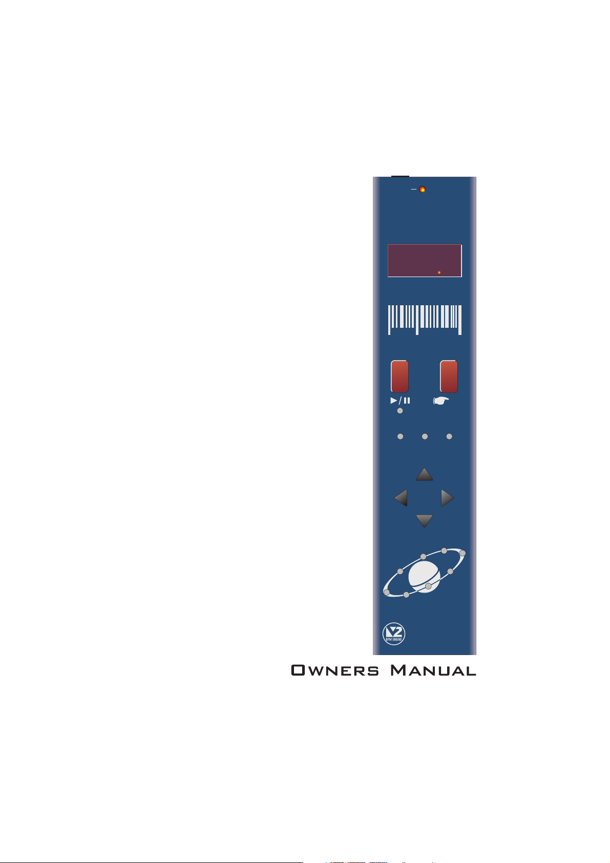
micro sync
Red
the colour of music
SYNC
BPM
UP
+/
PULL
NUDGE
8
413
8
4
bpm
Sound
RESET
STOP
OKPULL PUSH
PUSH
BPM
down
-/
TAP
/
micro sync
beat xtractor
BEAT 1
MIDI CLOCK
MIDI OUT
Issue 3


CONTENTS / INTRODUCTION
CONTENTS
Contents & Introduction ..........................................................................
Front Panel & Connectors .......................................................................
Mounting & Connections .........................................................................
External MIDI Sequencer Settings ..........................................................
OPERATION
Getting Started ............................................................................
Setting the Correct Input Level ..................................................
BPM Display ................................................................................
Run/Pause ...................................................................................
Tap (Reset/Stop) .........................................................................
Sync Indicator .............................................................................
Nudge Control ............................................................................
BPM Range. ................................................................................
Specification .......................................................Hints & Tips /
INTRODUCTION
Congratulations! By purchasing the MICRO SYNC you have joined an exclusive new club of
re-mixers and Djs who have discovered the future of DJ’ing, mixing MIDI instruments with
audio playback. Previously, to make MIDI happen in time with music was a matter of
painstaking and time-consuming tweaking of MIDI tempos and sound source pitch controls to
keep them even remotely synchronised.
1
2
3
4
4
5
5
6
7
7
8
11
12
The MICRO SYNC automatically synchronises audio and MIDI in a low-cost package with key
features to further simplify and enhance performance.
Sound's highly acclaimed ‘V2’ BPM Analysis Engine (taken from the groundbreaking
FEDERATION BPM FX module), which shoulders the responsibility of calculating the tempo of
the music. This leaves you free to concentrate on mixing and adjusting the real-time controls
on your MIDI sequencer/tone module.
With straight-forward connections and setup, a compact case and three mounting options, the
MICRO SYNC will integrate perfectly into any DJ/studio setup.
Please read the following sections of this manual carefully to fully understand the operation of
your new RED Sound MICRO SYNC Beat Xtractor.
At the heart of the MICRO SYNC is Red
OPERATING CRITERIA
This product has been designed to operate most effectively with dance music - i.e. music
based on strong regular beats and patterns. However, as the range of pre-recorded dance
material is virtually limitless (and the audio mix of individual tracks unknown) we cannot
guarantee the performance of the MICRO SYNC with every dance track.
The MICRO SYNC may operate unsatisfactorily if the beat information is either unavailable or
indefinable within the audio track. Please note this when selecting your audio material.
PAG E
1

FRONT PANEL/CONNECTORS
FRONT PANEL CONTROLS AND
CONNECTORS
Here’s a quick guide to the controls and connectors
on the MICRO SYNC.
1
AUDIO INPUT - Connector
Use the input cable ( to connect
socket to the
your mixing desk.
2
AUDIO INPUT LEVEL - Indicator
Use this bi-colour red/green LED to maintain the
ideal input level. See ‘ Input
Level ’on page 5.
3
POWER IN - Connector
Connect the output plug of the AC adaptor
supplied with the MICRO SYNC to this socket.
BPM - Display
4
The four digit BPM reading of the audio signal will
be displayed here.
RUN/PAUSE - Button
5
Press this button to run or pause the connected
MIDI sequencer. (Also sets the BPM range)
TAP (RESET/STOP) - Button
6
Tap this button to manually enter a BPM. Press
and hold the button to stop the MIDI clock and
reset the BPM display.
SYNCHRONISATION - Display
7
This 3-way indicator shows any synchronisation
adjustments.
supplied) this
booth/record or master output on
Setting the correct
1
4
2
INPUT
www.redsound.com
13841384
3
POWER
bpm
micro sync
Sound
Red
the colour of music
5
6
7
8
SYNC
BPM
UP
+/
PULL
NUDGE
RESET
STOP
OKPULL PUSH
PUSH
BPM
down
-/
TAP
/
NUDGE - 4 Buttons
8
Use this 4-way keypad to manually edit the BPM
reading or adjust the audio/MIDI sync point - see
page 8. (Also used for parameter editing)
MIDI CLOCK - Display
9
This 8 indicator display ‘rotates’ at the BPM rate
when the MICRO SYNC’s MIDI clock is running.
MIDI OUT - Connector
10
Use a suitable MIDI cable to connect this socket to
the MIDI IN connector on your sequencer.
PAG E
2
BEAT 1
9
MIDI CLOCK
MIDI OUT
10
MOUNTING/CONNECTIONS
MOUNTING THE MICRO SYNC
You can choose one of three mounting options
included with the MICRO SYNC.
1. - Stick one in each corner on
Rubber feet
the underside panel for free mounting.
2. - Stick one
Double sided adhesive pads
either side of the serial number label on the
underside panel. Locate a flat, clean surface
on your equipment/rig, peel-off film and press
firmly into place for a permanent mounting.
3.
Brackets, for use with 19” rack mount
holes on mixing desks
can be conveniently located on either side of a
mixing desk for a semi-permanent mounting.
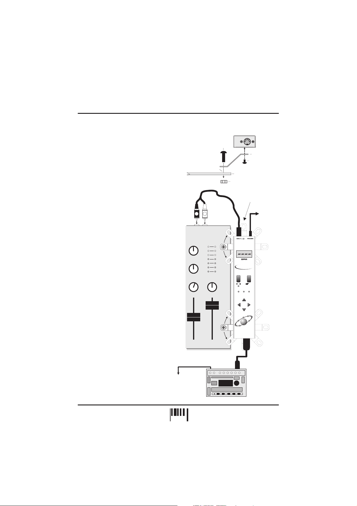
CONNECTING THE
MICRO SYNC TO YOUR
SYSTEM
When you have chosen the best
mounting option for your system setup,
connect the MICRO SYNC as follows:
1. Using the input cable ,
connect the 3.5mm plug end to the
MICRO SYNC
the panel.
rear
2. Connect the RCA phono plugs of the
cable to a suitable line level output on
your mixing desk. (Record, Booth etc.)
3.
Connect the output plug of the AC
power adaptor to the MICRO SYNC’s
power in socket on the rear panel.
Connect the MIDI OUT socket on the
4.
front panel of the MICRO SYNC to the
MIDI IN socket of your sequencer, using
a suitable MIDI cable.
socket marked ‘INPUT’ on
- The MICRO SYNC
supplied
TO SUB-MIXER: DO NOT
CONNECT MIDI AUDIO
SIGNAL BACK INTO MAIN
MIXER AS A FEED-BACK
LOOP WILL OCCUR.
M6 SCREW
19” RACK MOUNT HOLE
INPUT CABLE
(SUPPLIED)
R
L
RECORD/BOOTH
OR
MASTER OUTPUT
MIXING DESK
AUDIO OUT
MIDI SEQUENCER / TONE MODULE
MIDI IN
303/505
BRACKET
M3 SCREW
(LENGTH = 6mm MAX)
DJ MIXING DESK PANEL
M6 NUT
Rotate the chrome
brackets to line-up
with the 19” rack
mounting holes on
your mixing desk.
RED
MICRO SYNC
Beat Xtractor
/
TAP
(RESET
/STOP)
OKPULL PUSH
SYNC
BPM
+/UP
PULL
PUSH
BPM
-/DOWN
NUDGE
BEAT1
MIDICL OCK
MIDIOUT
SUITABLE
MIDI CABLE
TO AC
ADAPTOR
19” RACK
Hole pitch
range =
Min 90mm
Max 240mm
PAG E
3
 Loading...