

Red Sound Systems Infader Owner's Manual

INTRODUCTION
INTRODUCTION
InFader
DIGITAL DJ MIXING SYSTEM
Thank you for purchasing the RED Sound INFADER digital DJ mixing desk.
Digital technology is revolutionizing the world around us: digital audio, digital video, digital television, digital radio in all these fields digital technology is expanding our ideas of what is possible. Digital Signal Processing has
already delivered many of the technological innovations in audio which have driven the recording and re-mixing of
dance music. Sampling and effects processing are major parts of the re-mix process and many styles of dance
music just wouldn't have evolved without them. But up until now, the DJ has had to make do with the limitations of
analogue technology in the live arena.
Now, with INFADER, prepare to have your pre-conceptions of what a DJ Mixer can be blown away. Used to a
simple cross-fader? Or three kill switches for High, Mid and Low? Then how does a separate crossfader for High,
Mid and Low sound. Imagine being able to independently mix between the three separate frequency bands of your
source tracks, a feature so revolutionary Red Sound has patented it.
And the Tri-Fader Module is just the first of the digital innovations which Red Sound are developing to bring the
benefits of digital technology to live mixing. As the INFADER Digital DJ Mixing System expands, other exciting new
methods of processing the sound in live mixing will be added to the DJ's arsenal.
But INFADER already gives you three times the creativity of the conventional crossfader.
Let INFADER triple your mixing potential today.
1
OWNERS MANUAL
TOP PANELTOP PANEL
CH2
PREPRE
CH2
POSTPOST
FX LOOP (AUX)CHANNEL 1 CHANNEL 2 OUTPUTS
CLIP
MIN MAX
LEVEL
MASTER
CH1
SELECT
RETURN/
AUX
CH2
CHANNEL 2
PRE-TRIM
AUX
-
FX-AUXFX
7
4
MIC INSERT
RED
www.redsound.com
1
LINE
PRE-TRIM
-
CHANNEL 1
MIC
MIC - LINEMIC
LINE
POWER
+5
OUTPUT
LEVEL (VU)
+3
+1
0
-1
-3
-5
-7
-10
-15
MIN MAX
LEVEL
MASTER
MIN MAX
LEVEL
MASTER
CH1
CH1
SELECT
SEND
CLIP
PUSH
-12dB
+12dB
EQ - HIGH
MIN MAX
-12dB +12dB
MAX
EQ-LOW
MIN
LEVEL
LEVEL
BOOTH
CLIP
InFader
MIN MAX
-85dB +4dB
HIGH
TRIM
CD/
LINE
1
2
-85dB
+4dB
MID
CH 1CH
-85dB
+2dB
LOW
FX
ON
LOCK
5
OFF
ON
10
9
8
7
6
5
4
3
2
1
0
DIGITAL DJ MIXING SYSTEM
PHONO
+5
+3
+1
0
-1
-3
-5
-7
-10
-15
CD/
LINE
CH2 LEVELCH1 LEVEL
MIN MAX
TRIM
PHONO
10
9
8
7
6
5
4
3
2
1
0
-85dB +4dB
HIGH
+4dB
-85dB
MID
-85dB
+2dB
LOW
X-FADER
CURVE
2
3
CH 2CH
6
HIGH
MID
9
10
MASTER
X1
X-FADER MODE
SPLIT
X3
LOW
SPLIT CUE EQ CUT LEVEL SELECT PHONES
InFader - Digital DJ Mixing Desk
(MASTER)
TRI - FADERS
(Patent Pending)
2
HIGH
MID
LOW
RED
DIGITAL DJ MIXING SYSTEM
TRI-FADER MODULE
REVERSEREVERSE
NORMAL CENTRE OFF
X-FADER STATUS
8
11

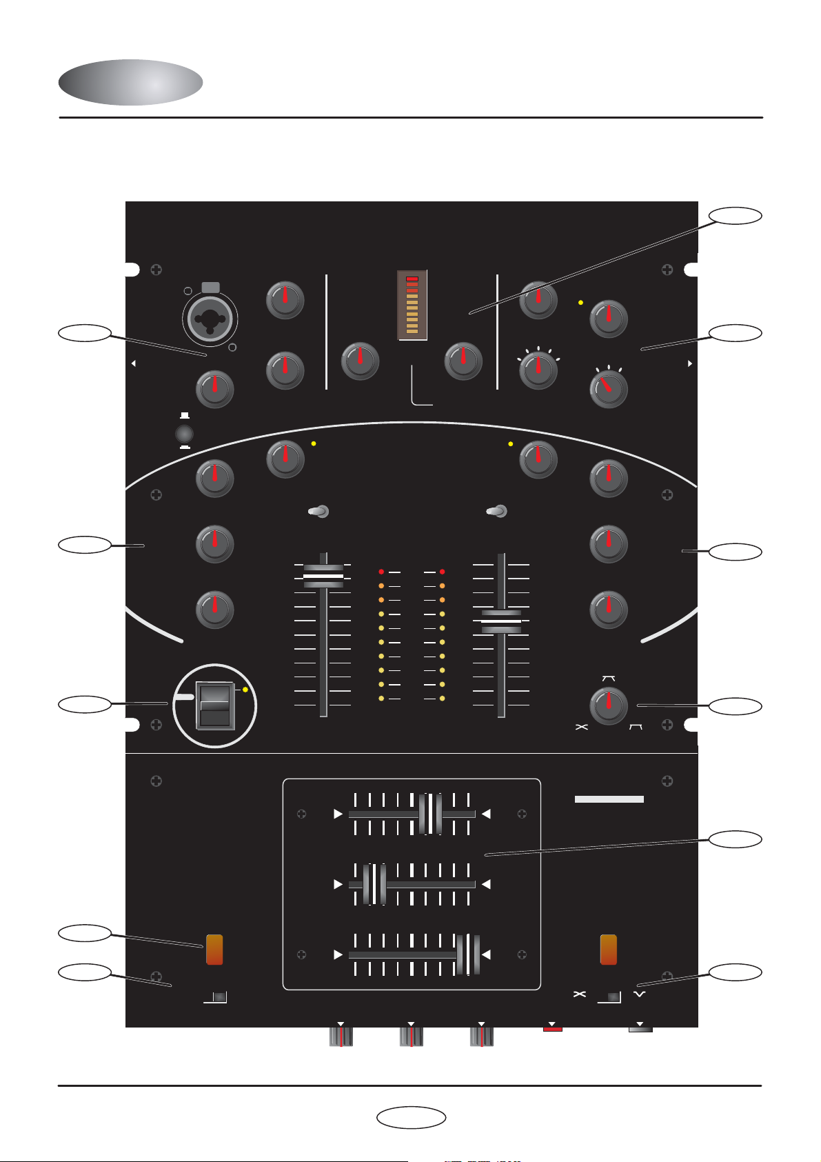
TOP PANEL FEATURESTOP PANEL FEATURES
FRONT PANEL FEATURES
1.
MIC/LINE INPUT:
microphone/line level input stage. The [MIC/LINE] push-button switch selects the input type. The combi-XLR
connector accepts XLR connectors for microphone use and ¼ Jack plugs for mono line level devices (CD/tape
players, drum machines, synthesizers etc.)
2.
CHANNEL 1 INPUT:
HIGH] controls for the channel 1 input stage. The [PRE-TRIM] control for this channel is situated on the left-hand
side panel. The bi-colour [CLIP] indicator shows the pre-A-to-D convertor level status. The 10-way indicator shows
channel level with 2 second peak-hold feature. This channel can be used with any CD/line or Phono level input
device.
3.
CHANNEL 2 INPUT:
HIGH] controls for the channel 2 input stage. The [PRE-TRIM] control for this channel is situated on the right-hand
side panel. The bi-colour [CLIP] indicator shows the pre-A-to-D convertor level status. The 10-way indicator shows
channel level with 2 second peak-hold feature. This channel can be used with any CD/line or Phono level input
device.
4.
FX SEND/RETURN - AUXILIARY INPUT:
/AUX LEVEL] and [RETURN/AUX SELECT] controls for the effects loop/auxiliary input stage. The bi-colour [CLIP]
indicator shows the pre-A/D convertor level status for the effects return/auxiliary input. The RETURN/AUX channel
can be used with any CD/line level input device.
This section features [LEVEL], [EQ-HIGH] and [EQ-LOW] controls for the selectable
This section features [TRIM], [INPUT SELECT], [LEVEL], [EQ-LOW], [EQ-MID] and [EQ-
This section features [TRIM], [INPUT SELECT], [LEVEL], [EQ-LOW], [EQ-MID] and [EQ-
This section features [SEND LEVEL], [SEND SELECT], [RETURN
5.
FX ON/OFF SWITCH:
6.
X- FADER CURVE:
7.
MASTER/BOOTH OUTPUT:
10-way VU indicator shows the MASTER output level.
8.
TRI-FADERS:
9.
REVERSE:
fader position(s) will be automatically reversed.
10.
X- FADER MODE:
[SPLITx3] mode (3-way crossfading).
11.
X- FADER STATUS:
CH2 sound ON) and [CENTRE OFF] status (fader in centre position = CH1, CH2 sound OFF).
This section features the [LOW/MASTER], [MID] and [HIGH] fader controls.
The two [REVERSE] buttons are connected in parallel. When either button is pressed, the current
This 3-way ‘paddle’ switch controls the effect send/return loop.
This control allows you to adjust the characteristics of the crossfader curve.
This section features the [MASTER LEVEL] and [BOOTH LEVEL] controls. The
This 2-way switch selects between [MASTERx1] mode (single crossfader operation) and
This 2-way switch selects between [NORMAL] status (fader in centre position = CH1,
3
OWNERS MANUAL
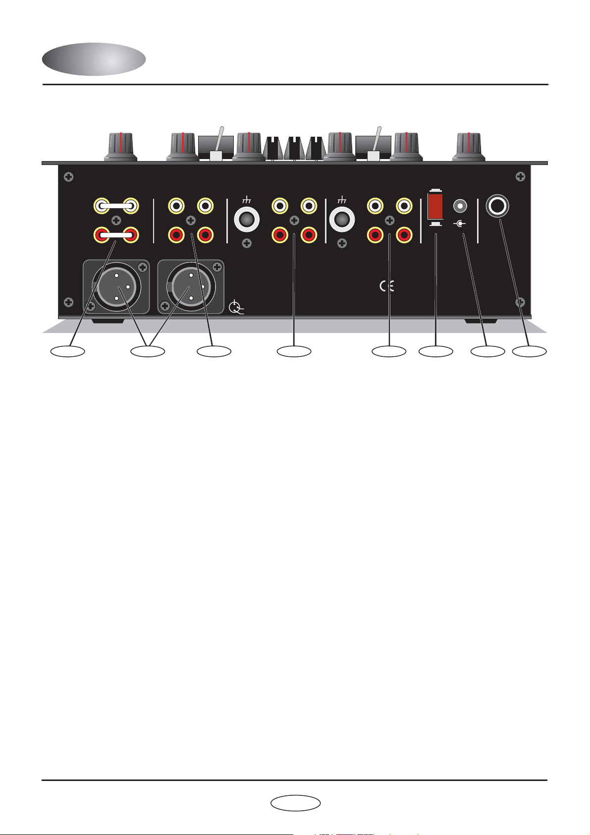
REAR PANELREAR PANEL
FX LOOP (AUX)
RETURN
(AUX IN)
RIGHT
SEND
MASTER OUTPUT (BALANCED)
OUTPUTS
BOOTHMASTER
LEFT
GND
CHANNEL 2
PHONOSIGNAL
CD/LINE
InFader
DIGITAL DJ MIXING SYSTEM
2 COLD
RED Sound Systems Ltd
3 HOT
1 GND
12 63 7485
1.
FX LOOP [AUX] - RCA Phono Connectors
SIGNAL
GND
CHANNEL 1
PHONO CD/LINE
LLLL
RRRR
POWER
16VDC
ON INSERT
-
OFF
REFER TO QUALIFIED SERVICE PERSONNEL
NO USER SERVICEABLE PARTS INSIDE
MADE IN ENGLAND
+
CAUTION: DO NOT OPEN CASE
Patent Pending
MIC
Use these sockets to connect any external effects processor to INFADER. Alternatively, you can use the
[RETURN/AUX IN] sockets to connect an additional stereo CD/line level sound source to INFADER for multichannel operation whilst using the [SEND] connectors as a RECORD out. INFADER is shipped with shorting bars
fitted between the send and return sockets to avoid ‘no output’ conditions when the front panel ‘FX’ switch is set to
on.
2.
BALANCED MASTER OUTPUTS - XLR Connectors
Use these sockets to connect INFADER to amplification systems supporting balanced XLR input.
3.
OUTPUTS - RCA Phono Connectors
Use the sockets marked [MASTER] to connect INFADER to amplification systems supporting unbalanced RCA
input. Use the sockets marked [BOOTH] to connect INFADER to the monitor amplification system.
4.
CHANNEL 2 - RCA Phono Connectors/Earth Terminal
Use the sockets marked [PHONO] and [SIGNAL GND] to connect the analog turntable to channel 2. Use the
sockets marked [CD/LINE] to connect the CD or line level audio player to channel 2.
5.
CHANNEL 1 - RCA Phono Connectors/Earth Terminal
Use the sockets marked [PHONO] and [SIGNAL GND] to connect the analog turntable to channel 1. Use the
sockets marked [CD/LINE] to connect the CD or line level audio player to channel 1.
6.
POWER - Switch
This turns the power on and off.
7.
DC POWER IN - Connector
IMPORTANT: Only use the 16vDC 750 mA PSU supplied with INFADER to power the unit.
8.
MIC INSERT - ¼ Jack Connector
Use this socket to send/return the MIC/LINE channel signal to an external sound processor.
InFader - Digital DJ Mixing Desk
4

INPUT CONNECTIONSINPUT CONNECTIONS
or...
CD / TAPE 3
RED FEDERATION BPM FX
OUT/IN
RESONANCE
1/3
BPM
+/UP
PULL
NUDGE
1/2
FILTER/LFO
1/3
-/DOWN
1/2
DELAY
PATT
PUSH
BPM
Max
Off
ENVMOD
1/1
3/4
2/3
BEATS
ACTIVATE
REPEAT
1/1
3/4
2/3
BEATS
ACTIVATE
1
1/4
INPUT
LEVEL
RED
FEDERATION
BPMFX- DJ
LGH/BAR
BPM
PULL
SYNCHRONISATION
FXMIXER
USERBEATS
2/3
BEATS
SHAPE
POS
1/4
PUSH
UTILITY
Off
1/4
LIVE (REC)
4
7
Triplet
2/1
1/1
3/4
SPEED
(MASTER)
2/1
USER
PATTERNSET
SetPatternLength
SetQuantize
SPEED
2/1
1/2
1/3
R
FX LOOP (AUX)
RETURN
SEND
(AUX IN)
RIGHT
MASTER OUTPUT (BALANCED)
L
R
www.redsound.com
FREQUENCY
1/4
SET(SPEED)
LEVEL
1/4
SET
(CLEARBPM)
TAP
Min
Max
Min
Max
SPEED
DEPTH
MONITOR
1/1
3/4
2/1
USER
2/3
1/2
1/3
BEATS
ACTIVATE
SET
CUTTER
Lo-Hi
2-Way
TM
Lo-Mid
Mid-Hi
Full
2-WAYSPLIT
SPEED
SPS
1/1
3/4
2/1
USER
2/3
1/2
1/3
BEATS
ACTIVATE
SET
PANNING
Whole
PROG.
BARLOOP
USER
MASTER
ON/OFF
Remove SHORTING BARS
before connecting FX device
GND
CHANNEL 2
PHONOSIGNAL
OUTPUTS
BOOTHMASTER
LEFT
InFader
DIGITAL DJ MIXING SYSTEM
2 COLD
RED Sound Systems Ltd
3 HOT
1 GND
CD / TAPE 1
CD/LINE
SIGNAL
GND
CD / TAPE 2
RRR
CHANNEL 1
PHONO CD/LINE
LLLL
RRRR
LLLL
POWER
ON
16VDC
-
+
OFF
CAUTION: DO NOT OPEN CASE
REFER TO QUALIFIED SERVICE PERSONNEL
NO USER SERVICEABLE PARTSINSIDE
MADE IN ENGLAND
Patent Pending
LINE LEVEL
AUDIO DEVICE
MIC
INSERT
Pin assignment
MICROPHONE
[balanced only]
Send
Return
Ground
or...
R L
L
R
ANALOG TURNTABLE 1 ANALOG TURNTABLE 2
TO
AC WALL
SOCKET
PSU
RED
OUT IN
OUT/IN
www.redsound.com
FREQUENCY
1/4
SET(SPEED)
LEVEL
1/4
SET
(CLEARBPM)
TAP
INPUT
LEVEL
RED
FEDERATION
BPMFX- DJ
Max
Off
RESONANCE
SPEED
ENVMOD
(MASTER)
1/1
3/4
2/1
USER
2/3
1/2
1/3
BEATS
ACTIVATE
PATTERNSET
FILTER/LFO
1/2
1/3
ACTIVATE
DELAY
PATT
BPM
+/UP
PULL
PUSH
BPM
-/DOWN
NUDGE
SYNCHRONISATION
SetPatternLength
SetQuantize
SPEED
REPEAT
1/1
3/4
2/1
2/3
BEATS
1122334
1/2
1/3
1/4
LGH/BAR
FXMIXER
USERBEATS
2/3
Min
Max
Min
SHAPE
POS
BPM
OKOKPULL
PUSH
UTILITY
LIVE (REC)
66554433221
Triplet
1/1
3/4
BEATS
Max
SPEED
DEPTH
MONITOR
1/1
3/4
2/1
USER
2/3
1/2
1/3
1/4
BEATS
ACTIVATE
SET
CUTTER
Lo-Hi
2-Way
TM
Lo-Mid
Off
Mid-Hi
Full
SPS
2-WAYSPLIT
SPEED
1/1
3/4
2/1
USER
2/3
1/2
1/3
1/4
BEATS
ACTIVATE
SET
PANNING
887
Whole
PROG.
BARLOOP
USER
2/1
MASTER
ON/OFF
RED FEDERATION BPM FX
(OR OTHER EFFECTS DEVICE)
5
OWNERS MANUAL
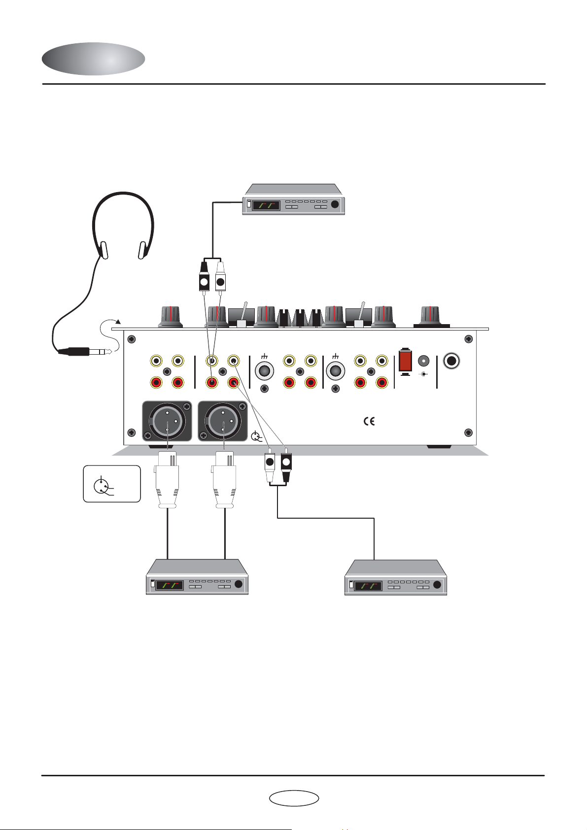
OUTPUT CONNECTIONSOUTPUT CONNECTIONS
POWER AMPLIFIER
(UN-BALANCED
RCA INPUT)
HEADPHONES
CONNECT TO
FRONT PANEL
SOCKET
2 COLD
Pin assignment
3 HOT
1 GND
FX LOOP (AUX)
RETURN
SEND
(AUX IN)
RIGHT
MASTER OUTPUT (BALANCED)
R
OUTPUTS
L
CHANNEL 2
PHONOSIGNAL
BOOTHMASTER
GND
LEFT
CD/LINE
InFader
DIGITAL DJ MIXING SYSTEM
2 COLD
RED Sound Systems Ltd
3 HOT
1 GND
L
R
SIGNAL
GND
CHANNEL 1
PHONO CD/LINE
LLLL
RRRR
POWER
16VDC
ON INSERT
-
+
OFF
CAUTION: DO NOT OPEN CASE
REFER TO QUALIFIED SERVICE PERSONNEL
NO USER SERVICEABLE PARTSINSIDE
MADE IN ENGLAND
Patent Pending
MIC
POWER AMPLIFIER
(BALANCED XLR INPUT)
InFader - Digital DJ Mixing Desk
POWER AMPLIFIER
FOR BOOTH MONITOR
6
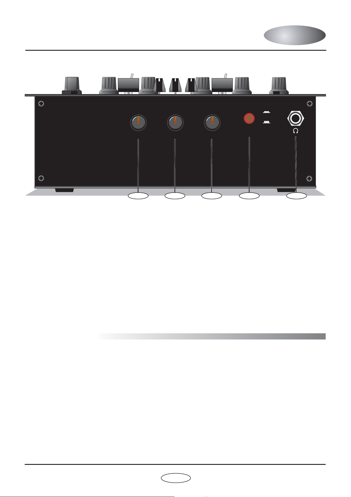
FRONT PANELFRONT PANEL
SPLIT CUE EQ CUT LEVEL SELECT PHONES
CH1
InFader
DIGITAL DJ MIXING SYSTEM
The front panel contains the following monitor controls:
1.
SPLIT CUE - Rotary
This control allows you to monitor channel 1, channel 2 or a mix of both when [SELECT] is set to CUE.
2.
EQ CUT - Rotary
This control can be used to change the CUE monitor EQ. To the left, high frequencies are cut and to the right, low
frequencies are cut.
3.
LEVEL - Rotary
This control sets the audio level to the connected headphones.
Off
MaxHigh CutCH2 MinLow Cut
CUE
MASTER
RED
www.redsound.com
45123
4.
SELECT - Pushbutton
This switch allows you to select MASTER or CUE monitoring.
5.
HEADPHONE OUT - Jack connector
Connect the ¼ jack plug from your headphones to this connector.
GETTING STARTED
Before use, please observe the following guidelines:
CONNECTIONS:
Connect the power supply (included) to the ‘power in’ socket on the rear panel of INFADER and plug it into a
suitable AC outlet. Connect the audio cables for a typical system setup as shown on pages 5/6.
TURNING ON THE POWER:
INFADER and the amplifier system are turned completely down. Press IN the rear panel power switch on
INFADER. Turn ON the power to the connected CD/analog players and amplifier system.
POWER ON INDICATION:
power is switched on. If this does not happen, check the power supply is of the correct type and the unit is switched
on and correctly connected.
INFADER is now ready for use.
Before making any connections, make sure that the power on all your equipment is turned OFF.
Make sure all connections have been made correctly and the volume controls on
When INFADER is powered up the [FX ON/OFF] indicator flashes to indicate that
7
OWNERS MANUAL
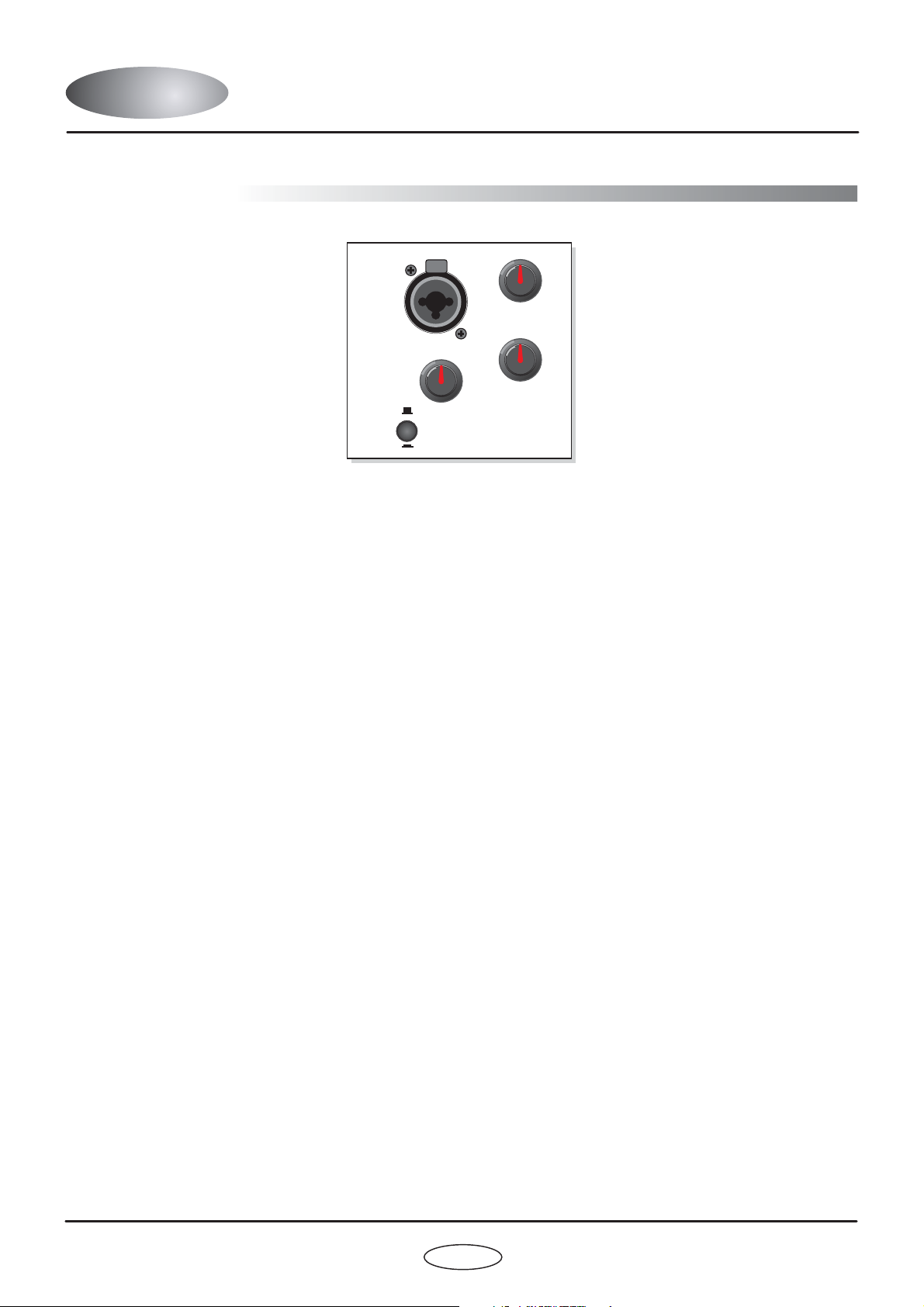
OPERATION
MIC / LINE INPUT
PUSH
-12dB
+12dB
EQ - HIGH
LINE
-
-12dB +12dB
MAX
EQ-LOW
MIN
LEVEL
MIC
MIC - LINEMIC
LINE
This section of INFADER features controls and connectors for the DJ microphone. The circuitry is totally analog
and is fed directly to the master output buss (also analog). The combination XLR/Jack connector allows you to use
this input as a 4th line-level input, ideal for introducing a further CD/tape player or other sound source such as MIDI
synthesizer/sequencer.
COMBI XLR CONNECTOR
This connector accepts the standard XLR plug fitted to BALANCED microphone cables. Before attempting to
connect the microphone, first ensure the [LEVEL] control is set to minimum and the [MIC/LINE] switch is set to the
[MIC] position (UP). Align the three pins on the plug with those on the socket and then push home fully until the
retaining latch clicks into place. To disconnect the microphone, first press down the retaining tab labelled [PUSH]
and then gently pull out the XLR microphone plug.
The centre area of this connector also accepts a standard ¼” jack plug for connecting line-level devices. Only mono
signals can be routed through this section. If a stereo 1/4” jack plug is inserted, the left/right channels will be
summed. Before attempting to connect the line-level device, first ensure the [LEVEL] control is set to minimum and
the [MIC/LINE] switch is set to the [LINE] position (DOWN). Push in the jack plug until it snaps into place. There is
no locking facility for this type of connector.
LEVEL CONTROL
This control sets the input level for the microphone or line-level device. At the fully anti-clockwise position there will
be no sound. As the control is moved in a clockwise direction the level will be gradually increased until, at the fully
clockwise position, the level will be at its maximum.
CARE!: This signal is routed to the master buss POST [MASTER] level control - e.g. the output level of the
microphone or line-level device will be un-affected by the [MASTER] level control.
EQ - LOW CONTROL
This control adjusts the bass equalisation of the microphone/line-level sound. At the 12 o’clock, centre click
position the low EQ will be flat (no cut or boost). As the control is moved anti-clockwise the low frequencies will be
progressively cut until, at the fully anti-clockwise position the maximum low frequency cut will be applied (-12dB).
As the control is moved clockwise from the centre position the low frequencies will be progressively boosted until,
at the fully clockwise position the maximum low frequency boost will be applied (+12dB@100Hz).
EQ - HIGH CONTROL
This control adjusts the treble equalisation of the microphone or line-level sound. At the 12 o’clock, centre click
position the high EQ will be flat (no cut or boost). As the control is moved anti-clockwise the high frequencies will be
progressively cut until, at the fully anti-clockwise position the maximum high frequency cut will be applied (-12dB).
As the control is moved clockwise from the centre position the high frequencies will be progressively boosted until,
at the fully clockwise position the maximum high frequency boost will be applied (+12dB@10kHz).
InFader -
Digital DJ Mixing Desk
8
 Loading...