

Red Sound Systems Darkstar XP2 Owner's Manual

Introduction
DARKSTAR XP2 SYNTHESIS
XP2
Thank you for purchasing the RED Sound DARKSTAR XP2 8-voice polyphonic synthesizer.
The Analogue Synthesiser, mainstay of Seventies' and Eighties' music, is back, reinvented in a new, more reliable
and flexible form. Physical modelling via powerful DSPs (Digital Signal Processors) allow all the warmth and control
of the synthesizers of yesteryear without the problems of unstable tuning and unrepeatable sounds, and with
modern benefits like realtime control and multitimbral access.
Welcome to DARKSTAR XP2, an 8-voice polyphonic synthesiser with all the highlights of the analogue tradition,
Pulse Width Modulation, Ring Mod, Resonant Filtering and ADSR Enveloping, combined with all the advantages of
modern MIDI instruments like rock-solid tuning, perfect program recall, velocity response and 5 different timbres
simultaneously available.
So whether your aim is to recreate 'classic' timbres like 70's Disco Bassline / Screaming PWM Lead, chart new
sonic territory with realtime joystick manipulation of filter frequency and resonance, or even combine both
approaches in the same MIDI sequence, DARKSTAR XP2 is the perfect tool for you.
In the future, DARKSTAR XP2's capabilities will grow thanks to the ability to install other EPROM-based DSP
algorithms. This will allow you to convert DARKSTAR XP2 into many different products such as a vocoder or mono
synth.
But DARKSTAR XP2 already offers so much with its marriage of proven synthesis techniques and state-of-the-art
control. Now it's time to unlock the potential of analogue-style synthesis with modern control techniques in your
music.
Be creative!
OWNERS MANUAL
PAG E
1
Front Panel
9
10
11
12
PORTAMENTO
TREMOLO
PANNING
LEVEL
SUB 2 PHONES
SUB 1
RIGHT
LEFT
INPUTS
EXTERNAL
2
Max
VELOCITY
RELEASE
7
Min
6
Max
+
SUSTAIN
Min
Max
DECAY
Min
Max
ATTACK
Min
5
4
3
2
1
0
VELOCITY LEVEL
Off
-
+
Off
-
SHIFT
0
Env 2
(0)
Envelopes
env 1
PART
OUTPUT
+10
-10
(+10)
(-10)
Max
Min
XP2
4
LFO2
LFO1
LFO 2 MOD
ENV MOD
RES MOD SOURCE
ENV1 ENV2
HI
RES MOD
RESONANCE
BAND
LO
FILTER TYPE
OFF
FILTER TYPE
FREQUENCY
SHIFT
Filter On
Filter
Filter Off
5
[Hold]
DEMo
[Press]
[+/up]
[-/dwn]
VOICE/
PROGRAM
MODULATION audition
MIDI
8
7
5
4
/
Sound
Red
the colour of music
EDIT
VALUE
/
PARAMETER
UTILITY
Y
X
JOYSTICK
3
PART SELECT
2
1
PORTA TRIGGER
MENUS
PART
LFO
6
osc mix
DETUNE
24
19
17
ring mod
16
PULSE WIDTH
12
7
PWM
5
OSC 2 SEMITONE OFFSET
PITCH MOD
0
www.redsound.com
OSC 2 PITCH
WAVEFORM
1
DARKSTAR XP2 - Poly Synth
Osc 2
Osc 1
Oscillators
SHIFT
MENU
VALUE
save
MASTER
FILTER
OSCILLATORS
EDIT
VOLUME
RANDOM
SHAPE
Max
Min
Max
Min
DELAY
SPEED
MIDI CLOCK
SAMPLE
PULSE
SINE
LFO SHAPE
SQUARE
TRI
RAMP
LFO 2
LFO’s
LFO 1
COMP
VALUE
SHIFT
3
PAG E
2
13

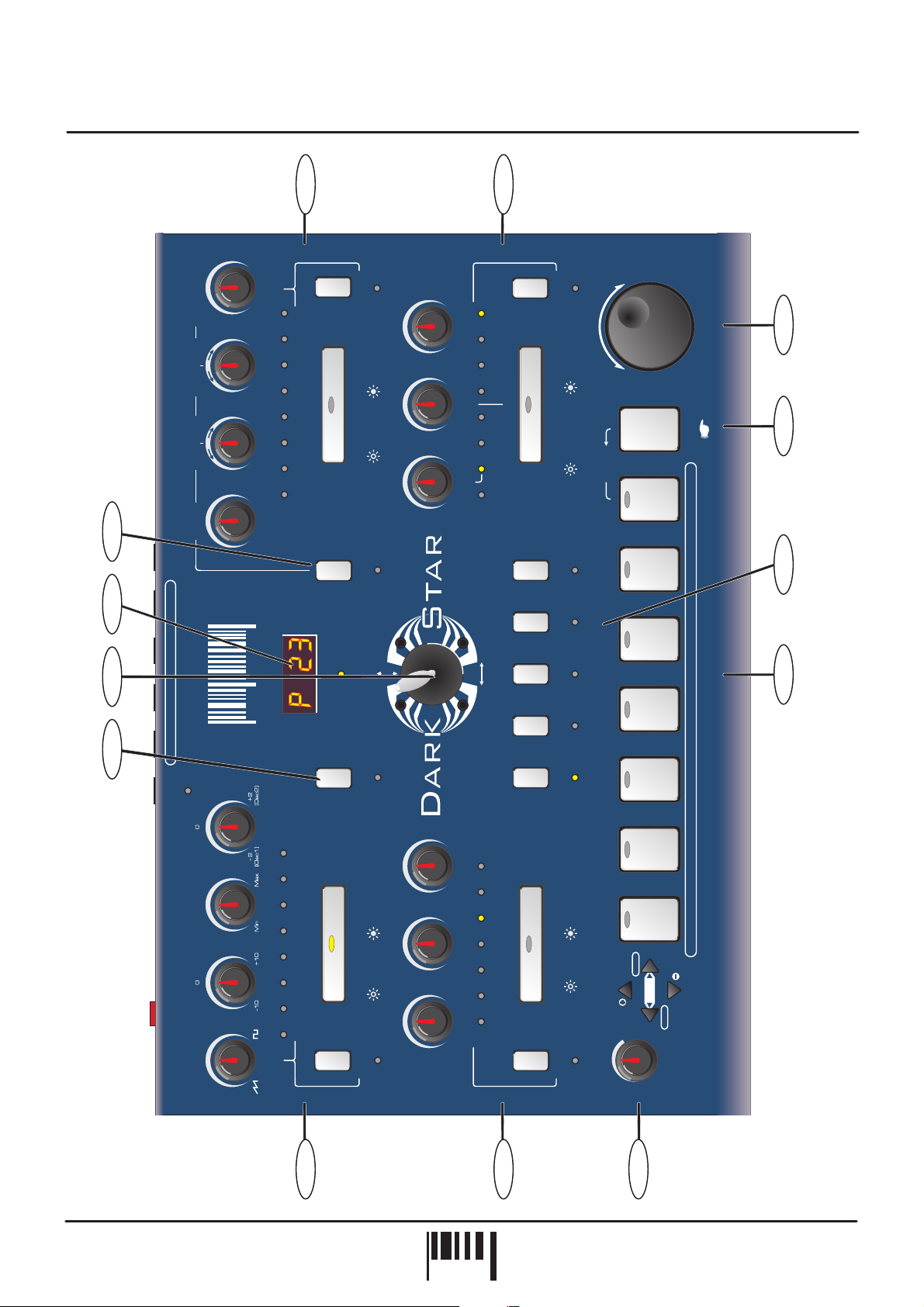
Front Panel Features
FRONT PANEL FEATURES
1.
OSCILLATORS:
for each oscillator. The large [OSCILLATOR] button switches between oscillators1&2.The[SHIFT] button is used
to access the [OSC 2 PITCH], [PWM], [RING MOD] & [OSC MIX] controls in the oscillator sub-menu.
2.
ENVELOPES:
envelope. The large [ENVELOPE] button switches between envelopes1&2.The[SHIFT] button is used to access
the [VELOCITY] control in the envelope sub-menu.
3.
LFO’S:
switches between LFO1&2.The[SHIFT] button is used to access the [MIDI CLOCK] control in the LFO submenu.
4.
FILTER:
[FILTER] button switches the filter on and off. The [SHIFT] button is used to access the [FILTER TYPE], [RES MOD]
and [LFO 2 MOD] controls in the oscillator sub-menu.
5.
PART SELECT:
totally different sounds in each program.
This section features [SPEED], [DELAY] and [SHAPE] controls for each LFO. The large [LFO] button
This section features [FREQUENCY], [RESONANCE] and [ENV MOD] controls for the filter. The large
This section features [WAVEFORM], [PITCH MOD], [PULSE WIDTH] and [DETUNE] controls
This section features [ATTACK], [DECAY], [SUSTAIN] and [RELEASE] controls for each
These buttons are used to select the 5 Multitimbral ‘PARTS’. You can create and store five
6.
MENU:
additional parameters for editing whilst the [EDIT] keypad is used to scroll up and down the menu and change the
values.
7.
AUDITION:
menu button, the [DEMO] sequence can be accessed.
8.
VOICE/PROGRAM:
9.
PART OUTPUT:
parameters for each individual PART.
10.
information and edit values.
11.
JOYSTICK:
[FREQUENCY] + [RESONANCE] parameters can be controlled by the joystick simultaneously.
12.
menus along with various SYSTEM EXCLUSIVE parameters.
This section features 7 menu buttons and a 4-way keypad. The MENU buttons are used to select
This button can be used to trigger the selected PART. Also, in conjunction with the MODULATION
This jog dial is used to call-up the programs and voices.
This button is used to access the [LEVEL], [PANNING], [TREMOLO] and [PORTAMENTO]
PARAMETER/VALUE DISPLAY:
The joystick mixer can be assigned to a number of different parameters. For example filter
UTILITY:
This button is used to access the [JOYSTICK], [OUTPUT ASSIGN] and [MASTER MIDI CHANNEL]
This 4-digit LED display shows voice/program numbers, parameter
OWNERS MANUAL
PAG E
3
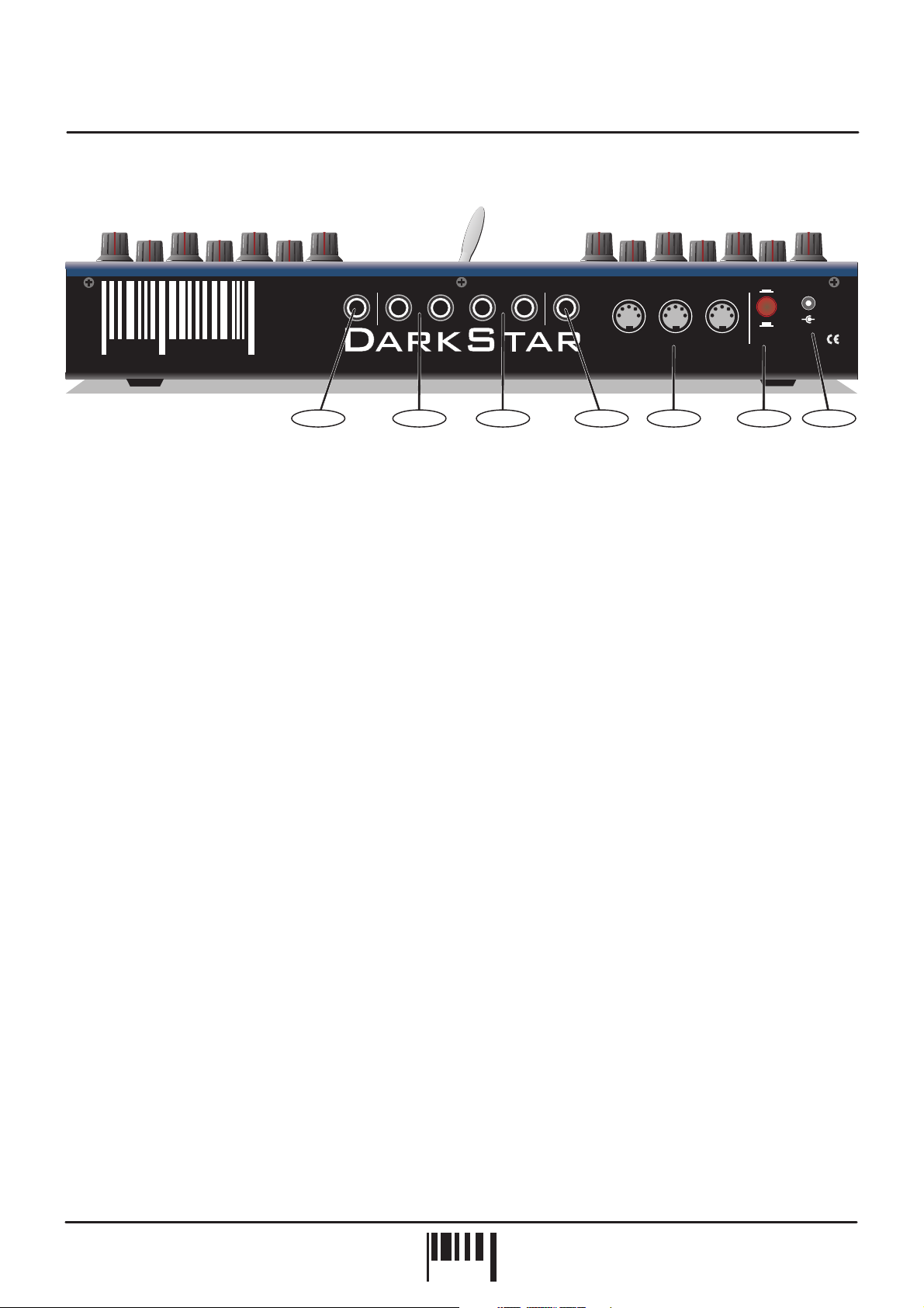
Rear Panel
Red
the colour of music
1.
HEADPHONES - 1/4 jack connector
Sound
RIGHT [2][2] LEFT [1] TIP[1] RING[2] THRU OUT IN[1]
www.redsound.com
1423 5 67
XP2
CAUTION: DO NOT OPEN CASE. REFER TOQUALIFIED SERVICE PERSONNEL. NO USER SERVICEABLE PARTS INSIDE
MIDIEXTIN1&2MAIN OUTPUTSSUB OUTPUTSPHONES
Red Sound Systems Ltd
ON
MADE IN ENGLAND
POWER
-
9v DCOFF
+
Use this socket to monitor the MAIN output signal from DARKSTAR XP2. Use suitable stereo headphones of
50 ohms > impedance (NOTE: the SUB outputs cannot be monitored from this connector).
2.
SUB OUTPUTS - 1/4 jack connectors
Use these sockets to feed the secondary pair of audio outputs to your mixing desk or amplification system.
3.
MAIN OUTPUTS - 1/4 jack connectors
Use these sockets to feed the main left/right audio output of DARKSTAR XP2 to your mixing desk or amplification
system.
4.
EXTERNAL INPUTS 1&2 - 1/4 jack connector
Use this socket to connect any external line level audio source to DARKSTAR XP2 for filter/envelope processing
whilst using MIDI control.
5.
MIDI IN/OUT/THRU - Connectors
MIDI data will be transmitted and received by these connectors.
6.
POWER - Switch
This turns the power on and off.
7.
DC POWER IN - Connector
Only use the 9vDC 500 mA [or greater amperage] PSU supplied with DARKSTAR XP2 to power the unit.
DARKSTAR XP2 - Poly Synth
PAG E
4
PSU
RED
TO
SOCKET
AC WALL
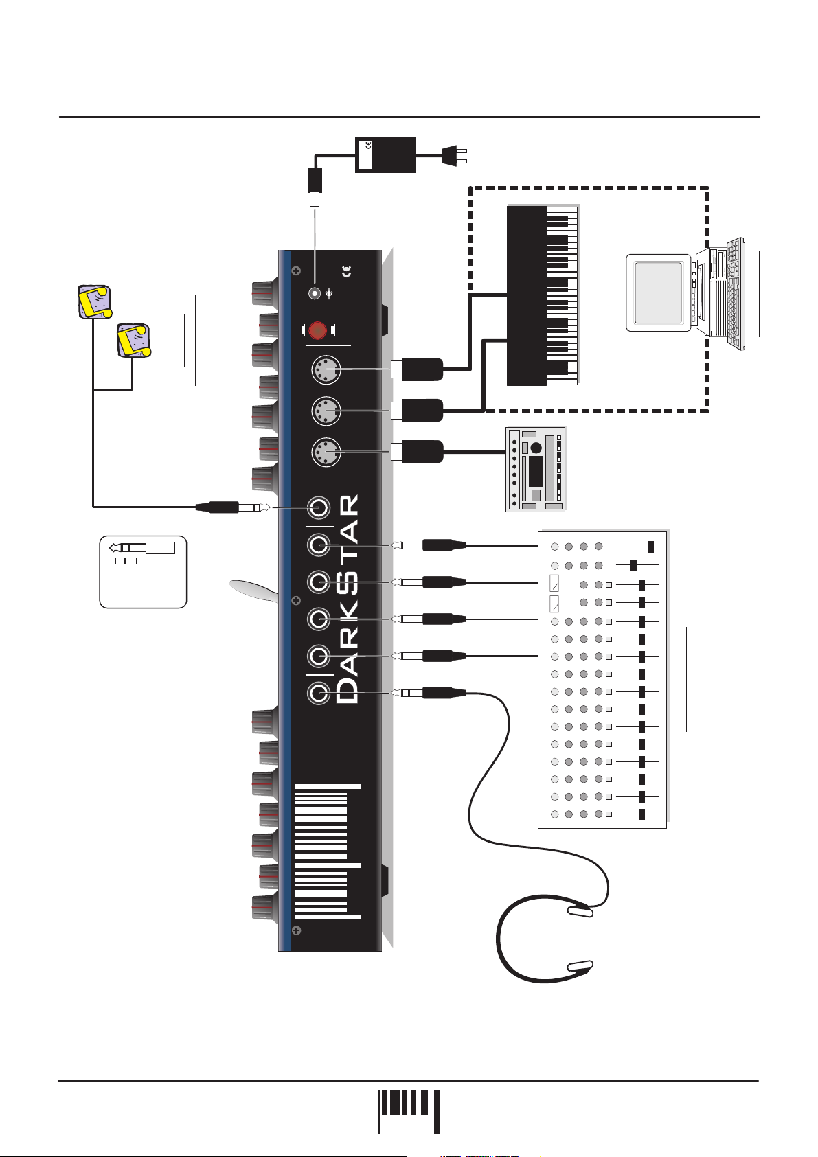
Connections
MIDI OUT
Input 1
ONE
Input 2
TWO
Ground
EXTERNAL
SOUND SOURCES
POWER
ON
IN
OUT
MIDI
THRU
TIP[1] RING[2]
EXTIN1&2
LEFT [1]
MAIN OUTPUTS
RIGHT [2]
[1]
[2]
SUB OUTPUTS
+
-
9v DC
MADE IN ENGLAND
OFF
Red Sound Systems Ltd
CAUTION: DO NOT OPEN CASE. REFER TOQUALIFIED SERVICE PERSONNEL. NO USER SERVICEABLE PARTS INSIDE
or...
XP2
MIDI OUT
MIDI KEYBOARD
MIDI IN
or...
MIDI IN
MIDI SEQUENCER
MIDI IN
OTHER MIDI DEVICE
PHONES
www.redsound.com
Sound
Red
the colour of music
STUDIO MIXING DESK
HEADPHONES
OWNERS MANUAL
PAG E
5
Quick Start
QUICK START
If you want to quickly try out the performance of DARKSTAR XP2, please read the following points carefully:
CONNECTIONS:
Connect the power supply (included) to the ‘power in’ socket on the rear panel of DARKSTAR XP2 and plug it into
a suitable AC outlet. Connect the audio cables for a basic system setup as shown on page 5.
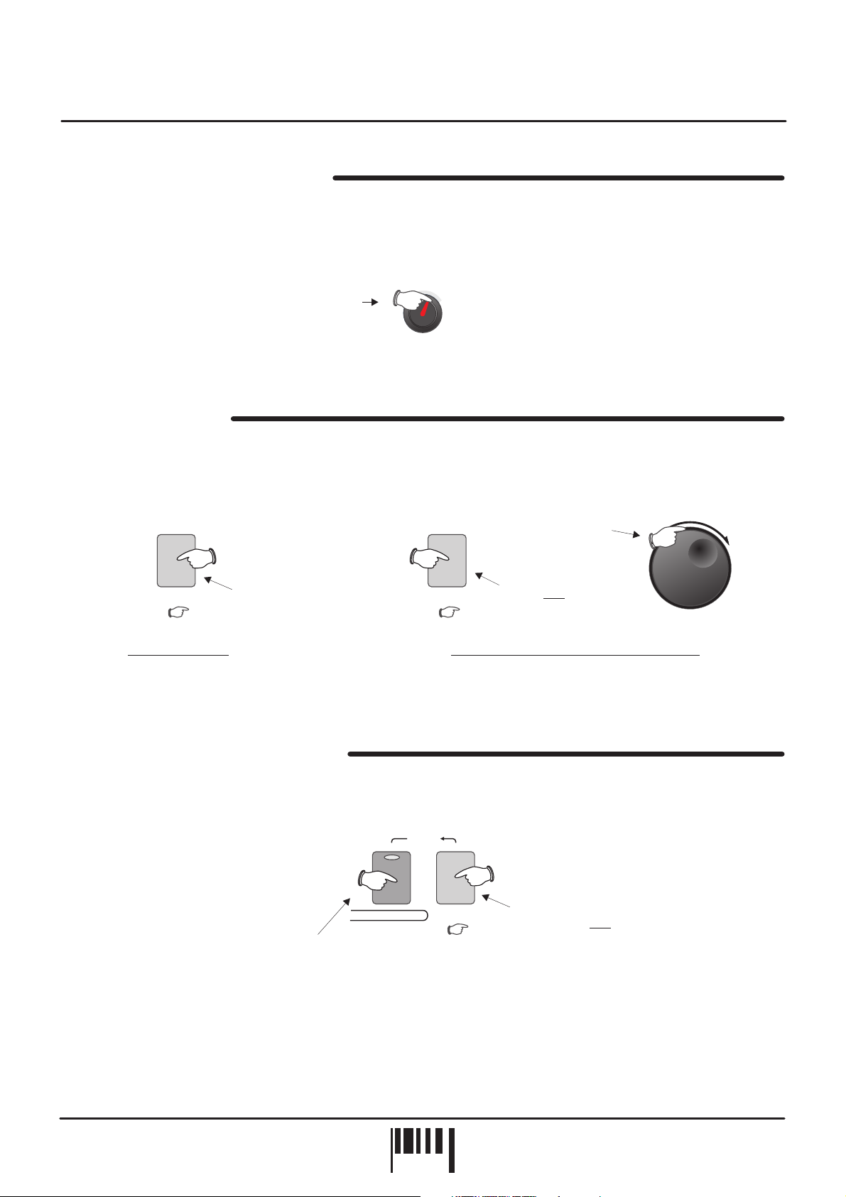
TURNING ON THE POWER:
mixing desk and amplifier system are turned completely down. Press the rear panel power switch on DARKSTAR
XP2. Turn on the power of the mixing desk and then turn on the power of the amplifier system.
POWER UP INDICATIONS:
message whilst various parameters are being set internally. When this process is complete, the display will show
the PROGRAM number. If this does not happen, check the power supply is of the correct type and the unit was
switched on correctly.
PLAYING THE DEMO:
[MODULATION] menu button once to start playback. To pause the demo simply press the [AUDITION] button once.
SETTING THE MIDI RECEIVE CHANNEL:
button and use the [EDIT] keypad [VALUE +] and [VALUE -] buttons to set the channel of the active PART (as
DARKSTAR XP2 can have up to 5 different sounds/MIDI channels setup in each PROGRAM you may have to
change the MIDI transmit channel on your keyboard a few times to play all the sounds).
SELECTING PROGRAMS:
the display will start to flash the ‘P’ for program. Now simply rotate the [VOICE/PROGRAM] jog dial to scroll up and
down the 64 programs. Whilst the new program data is being loaded the display will flash ‘PL’ for program load wait for this to revert to ‘P’ before attempting to audition the new sound.
Before making any connections, make sure that the power on all your equipment is turned OFF.
Make sure all connections have been made correctly and the volume controls on the
When DARKSTAR XP2 is powered up, the main display will briefly show a welcome
To run the demo sequence, press and the [AUDITION] button, then press the
To select the correct MIDI receive channel, press the [MIDI] MENU
To select the factory programs, press the [VOICE/PROGRAM] jog dial knob once and
hold
To hear the sounds, use the front panel [AUDITION] button or connected MIDI keyboard. You can modify the
sounds in real-time by altering the controls in the OSCILLATOR, FILTER, ENVELOPE and LFO sections.
Please read the following “OPERATION” section carefully to fully appreciate the range of features and facilities the
DARKSTAR XP2 8-Voice Synthesizer has to offer.
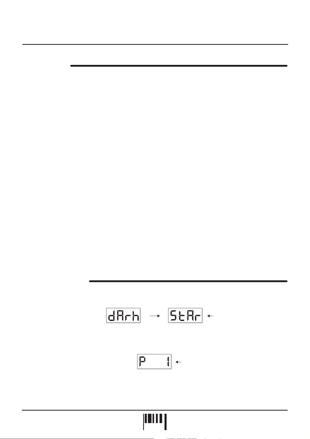
GETTING STARTED
After connecting DARKSTAR XP2 to your system as detailed on page 5, press IN the rear panel power switch to
turn the power on. The main display will show a welcome message, as shown below:
Welcome message = dArk StAr
PARAMETER
VA L U E
Afterwards, the last selected program (before power was switched off at the previous session) will be recalled and
displayed as follows:
PARAMETER
VA L U E
DARKSTAR XP2 is now ready to use.
PARAMETER
VA L U E
Program 1
DARKSTAR XP2 - Poly Synth
PAG E
6
Operation
MASTER VOLUME CONTROL
Use this control to set the master output level of DARKSTAR XP2. The position of this rotary control will determine
the overall output level from the rear panel [MAIN] left/right, [SUB]1&2audio sockets and also the [PHONES]
monitor output. At the fully anti-clockwise position the output will be zero. As the knob is moved in a clockwise
direction the output level will gradually increase until, at the fully clockwise position the overall volume will be at its
maximum.
Rotate clockwise
to increase MASTER
VOLUME
MASTER
VOLUME
AUDITION Button
This feature allows you to trigger sounds whilst working at the front control panel. There are single note triggers,
chords and patterns to choose from enabling you to try sounds in a number of different ways. Each press of the
[AUDITION] button will trigger the sound and the [VOICE/PROGRAM] jog dial can be used to change the trigger
pattern, as shown in the following examples:
Rotate the JOG DIAL
2
to change the
AUDITION TRIGGER
[+/up][-/dwn]
1
audition audition
Playing a sound Changing the AUDITION trigger pattern
The display will indicate the selections as the jog dial is rotated. The selected trigger type can be stored with the
program.
DEMONSTRATION SEQUENCE
To play the DARKSTAR XP2 demo sequence, first press and hold down the [AUDITION] button, then press the
[MODULATION] menu button once, as shown in the following example:
To pause the demo at any time simply press the [AUDITION] button once.
Press once to
trigger sound
To play the demo...
2
Press once
DEMo
[Hold][Press]
auditionMODULATION
Press & hold
Press and hold
1
VOICE/
PROGRAM
OWNERS MANUAL
PAG E
7
Operation
PROGRAMS - Selecting, editing and saving sounds
This section allows you to store all the DARKSTAR XP2 settings in memory for instant recall of your favourite
sounds. The position of every control knob, switch and even the joystick can be memorised in 64 user definable
program memory locations.
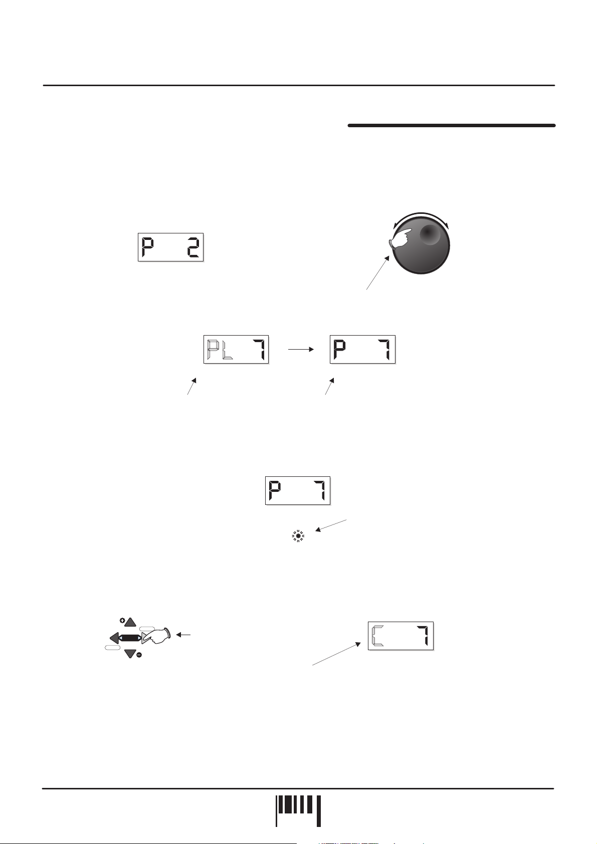
SELECTING PROGRAMS:
Use the [VOICE/PROGRAM] jog dial to select programs from memory, as shown in the
following example:
[+/up][-/dwn]
EDITING:
PARAMETER
VA L U E
Display shows current PROGRAM number
PARAMETER
VA L U E
Display flashes ‘PL’ to indicate
3
PROGRAM LOADING
...then ‘P 7’ as the new
PROGRAM is loaded in
Rotate clockwise or anti-clockwise to change PROGRAM1
2
PARAMETER
VA L U E
To edit the selected program simply adjust any of the front panel controls. When the first control or switch
VOICE/
PROGRAM
is moved, the [EDIT] indicator will start to flash to indicate ‘EDIT’ mode, as shown in the following example:
PARAMETER
VA L U E
EDIT
don’t
If you want to keep the parameter changes made during editing, simply select another program.
COMPARE:
To hear the ORIGINAL settings of the selected program (before it was edited), press the EDIT -
Flashes to indicate program EDIT mode
[COMP] button once, as shown below:
VALUE
save
MENU
EDIT
COMP
VALUE
Press the compare [COMP]
button to hear the original
sound
Display changes to ‘C’
to indicate COMPARE mode
PARAMETER
VA L U E
You can switch from ‘Edit’ to ‘Compare’ modes as often as you like, simply press the [COMP] button again to jump
from one mode to the other.
DARKSTAR XP2 - Poly Synth
PAG E
8
Operation
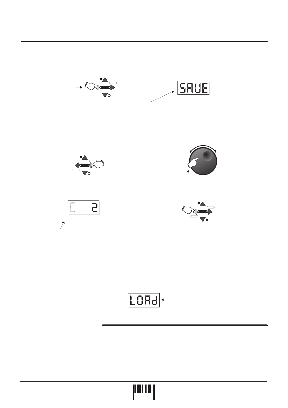
STORE IN EXISTING PROGRAM:
If you want to store the new settings, they can be saved into the current
program whereby any previous settings will be overwritten. To store the new settings simply press the EDIT [SAVE]
button once, as shown below:
VALUE
COMP
Press the save [SAVE]
button once to store the
edited sound
save
MENU
EDIT
VALUE
Display changes to confirm
SAVE operation
PARAMETER
VA L U E
The main display will show 'SAVE' whilst the store operation is carried out.
STORE IN ANOTHER PROGRAM:
If you want to keep the existing program the edited setup, you
and still save
can overwrite any of the other programs. First, activate COMPARE mode and then use the [VOICE /PROGRAM]
jog dial to select another suitable program location as shown below:
VALUE
MENU
save
EDIT
Press the COMPARE button once
1
PARAMETER
VA L U E
COMP
VALUE
Rotate to select new PROGRAM
2
VALUE
MENU
save
EDIT
[+/up][-/dwn]
VOICE/
PROGRAM
COMP
VALUE
Display ‘C’ letter now flashes to indicate
3
COMPARE SELECT mode
When you are sure you want to overwrite the
4
selected program press SAVE
The 64 factory presets can be re-loaded back into memory at any time.
RE-LOAD ALL 64 FACTORY PRESETS: Ensure power is switched OFF. hold down
Press and the
[VOICE/PROGRAM] jog dial knob and then turn power on. The main display will show ‘SURE’ to prompt
confirmation of the load. Press the top [EDIT] button marked ‘VALUE +’’ to confirm the operation (‘LOAD’ appears
briefly in display).
Loading back all 64 factory presets
PARAMETER
VA L U E
PART MENU FUNCTIONS
The [PART] menu button at the front of the main panel lets you setup parameters such as POLYPHONY, MIDI
CHANNEL, NOTE RANGE, TRANSPOSE etc for each sound. For full details on the menu list, functions and
settings please see pages 22, 23 and 24.
OWNERS MANUAL
PAG E
9
Operation
OSCILLATOR SECTION
OSC 2 PITCH
SHIFT
PITCH MODWAVEFORM
PWM ring mod osc mix
OSC 2 SEMITONE OFFSET
1716 19 2412750
Oscillators
Osc 1
Osc 2
DETUNEPULSE WIDTH
This section of DARKSTAR XP2 produces the musical tones which form the basis of subtractive synthesis. There
are two oscillators per ‘voice’ (musical note), each producing audible vibrations to act as a sound source. The
timbre of each oscillator depends on its harmonic content which is determined by the waveform. There are basically
two waveforms available, SAWTOOTH and SQUARE, each with its own specific set of harmonics.
Controls for changing the amount of modulation to the pitch timbre of the oscillators are also included in this
section. These timbral and pitch modulations give the oscillator sound more depth and stimulate musical appeal to
the ear.
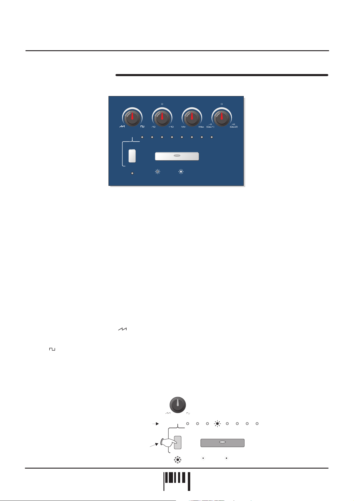
OSCILLATOR SELECT button
This large button switches between oscillator 1 and 2. When the indicator is OFF, oscillator 1 will be selected.
When the indicator is ON, oscillator 2 will be selected.
WAVEFORM
(OSC 2 PITCH)
This control has two functions determined by the [SHIFT] button.
When the [SHIFT] function is (SHIFT LED Off) this control sets the selected oscillator’s waveform.
NOT selected ,
At the fully anti-clockwise position ( ) the waveform will be shaped like a SAWTOOTH. This waveform contains
every harmonic in decreasing volume and produces a very rich sound. As the control is moved in a clockwise
direction the shape progressively changes, becoming more and more ‘squared-off’ until, at the fully clockwise
position ( ) the shape will be a SQUARE or ‘pulse’ waveform. As a pure square wave (max and min values equal)
the harmonic content will be all the odd-numbered harmonics in decreasing volume which gives the sound a hollow
or ‘woody’ timbre. The width of the pulse can also be altered by the [PULSE WIDTH] knob to make the sound
thinner.
When the [SHIFT] function is selected (SHIFT LED Flashing) this control sets the amount of oscillator 2 pitch
,
offset. This detune setting is calibrated in semitones with the eight indicators labelled [OSC 2 SEMITONE OFFSET]
showing the value, as in the following example:
WAVEFORM
Oscillator 2 pitch offset =
Example:
12 semitones (1 octave)
Press once
before changing
the setting
OSC 2 PITCH
SHIFT
OSC 2 SEMITONE OFFSET
1716 19 2412750
Oscillators
Osc 1
Osc 2
DARKSTAR XP2 - Poly Synth
PAG E
10

Operation
PITCH MOD
This control has two functions determined by the [SHIFT] button.
When the [SHIFT] function is (SHIFT LED Off) this control sets the amount of pitch modulation to
the selected oscillator. At the 12 o’clock position there will be no pitch modulation applied. As the knob is moved in
an anti-clockwise direction the pitch modulation will become negative, first falling then rising. At the fully anticlockwise position the modulation will be at its maximum negative depth. As the knob is moved in a clockwise
direction from the centre position, the pitch modulation will become positive, first rising then falling. At the fully
clockwise position the modulation will be at its maximum positive depth. See [OSCILLATOR] menu section below
for further details on the pitch modulation source.
When the [SHIFT] function is selected (SHIFT LED Flashing) this control sets the amount of pulse width
modulation or PWM for the selected oscillator when its [WAVEFORM] is set to SQUARE ( ). The PWM
SOURCE can be set to LFO1, LFO2, ENV1 or ENV2 (see [OSCILLATOR] menu) with negative and positive
modulations available. At the 12 o’clock position there will be no PWM. As the knob is moved in an anti-clockwise
direction the variation in the pulse width will become more and more pronounced in a negative manner. As the
knob is moved in a clockwise direction the variation in the pulse width will become more and more pronounced in a
positive manner.
PULSE WIDTH
This control has two functions determined by the [SHIFT] button.
When the [SHIFT] function is (SHIFT LED Off) this control sets the actual width of the pulse. At the
fully anti-clockwise position the fundamental will be at its minimum producing an extremely thin sound. As the knob
is moved in a clockwise direction the pulse width gets wider, with progressively less high harmonics being added
giving the sound a fuller timbre. At the fully clockwise position the minimum and maximum values of the pulse width
will be equal.
(PWM)
NOT selected ,
,
[RING MOD)
NOT selected ,
When the [SHIFT] function is selected (SHIFT LED Flashing) this control sets the amount of ring modulation
applied to the sound. Ring modulation occurs when the two sound sources are multiplied together and this gives
the resultant sound a harder, over-driven edge. At the fully anti-clockwise position the ring modulation will be at its
minimum. As the knob is moved in a clockwise direction the ring modulation gradually increases until, at the fully
clockwise position the ring modulation effect will be at its maximum.
DETUNE
This control has two functions determined by the [SHIFT] button.
When the [SHIFT] function is (SHIFT LED Off) this control sets the fine tuning for each oscillator. At
the 12 o’clock position the oscillators tuning will be unaffected. As the knob is moved in an anti-clockwise direction
the oscillators tuning will become more ‘Flat’, with a total negative detune of - 2 semitones available at the fully anticlockwise position. As the knob is moved in a clockwise direction the oscillators tuning will become more ‘Sharp’,
with a total positive detune of + 2 semitones available at the fully clockwise position. Small variations in the
oscillators relative tuning will fatten up a sound giving it a rich texture. Larger amounts of detuning create a more
extreme effect.
When the [SHIFT] function is selected (SHIFT LED Flashing) this control sets the mix level between the oscillators.
At the 12 o’clock position the level of both oscillators will be equal. As the knob is moved in an anti-clockwise
direction the level of oscillator 2 will begin to decrease until, at the fully anti-clockwise position, only oscillator 1 can
be heard. As the knob is moved in a clockwise direction the level of oscillator 1 will begin to decrease until, at the
fully clockwise position, only oscillator 2 can be heard.
OSCILLATOR MENU
This section contains the remaining functions for the oscillators. To access these settings, press the MENU button
labelled [OSCILLATORS], as shown in the following example:
[OSC MIX)
NOT selected ,
,
,
OWNERS MANUAL
PAG E
11
 Loading...