

Red Sound Systems Darkstar Owner's Manual

INTRODUCTION
DARKSTAR SYNTHESIS
Thank you for purchasing the RED Sound DARKSTAR 8-voice polyphonic synthesizer.
The Analogue Synthesiser, mainstay of Seventies' and Eighties' music, is back, reinvented in a new, more reliable
and flexible form. Physical modelling via powerful DSPs (Digital Signal Processors) allow all the warmth and control
of the synthesizers of yesteryear without the problems of unstable tuning and unrepeatable sounds, and with
modern benefits like realtime control and multitimbral access.
Welcome to DARKSTAR, an 8-voice polyphonic synthesiser with all the highlights of the analogue tradition, Pulse
Width Modulation, Ring Mod, Resonant Filtering and ADSR Enveloping, combined with all the advantages of
modern MIDI instruments like rock-solid tuning, perfect program recall, velocity response and 5 different timbres
simultaneously available.
So whether your aim is to recreate 'classic' timbres like 70's Disco Bassline / Screaming PWM Lead, chart new
sonic territory with realtime joystick manipulation of ring modulation and velocity controlled resonance, or even
combine both approaches in the same MIDI sequence, DARKSTAR is the perfect tool for you.
In the future, DARKSTAR's capabilities will grow thanks to the ability to change its EPROM-based DSP algorithms.
This will allow you to convert DARKSTAR into many different products such as a mega-mono synthesizer or
vocoder.
But DARKSTAR already offers so much with its marriage of proven synthesis techniques and state-of-the-art
control. Now it's time to unlock the potential of analogue-style synthesis with modern control techniques in your
music.
Be creative!
OWNERS MANUAL
1
DarkStar
8 VOICE POLYPHONIC SYNTHESIZER
2
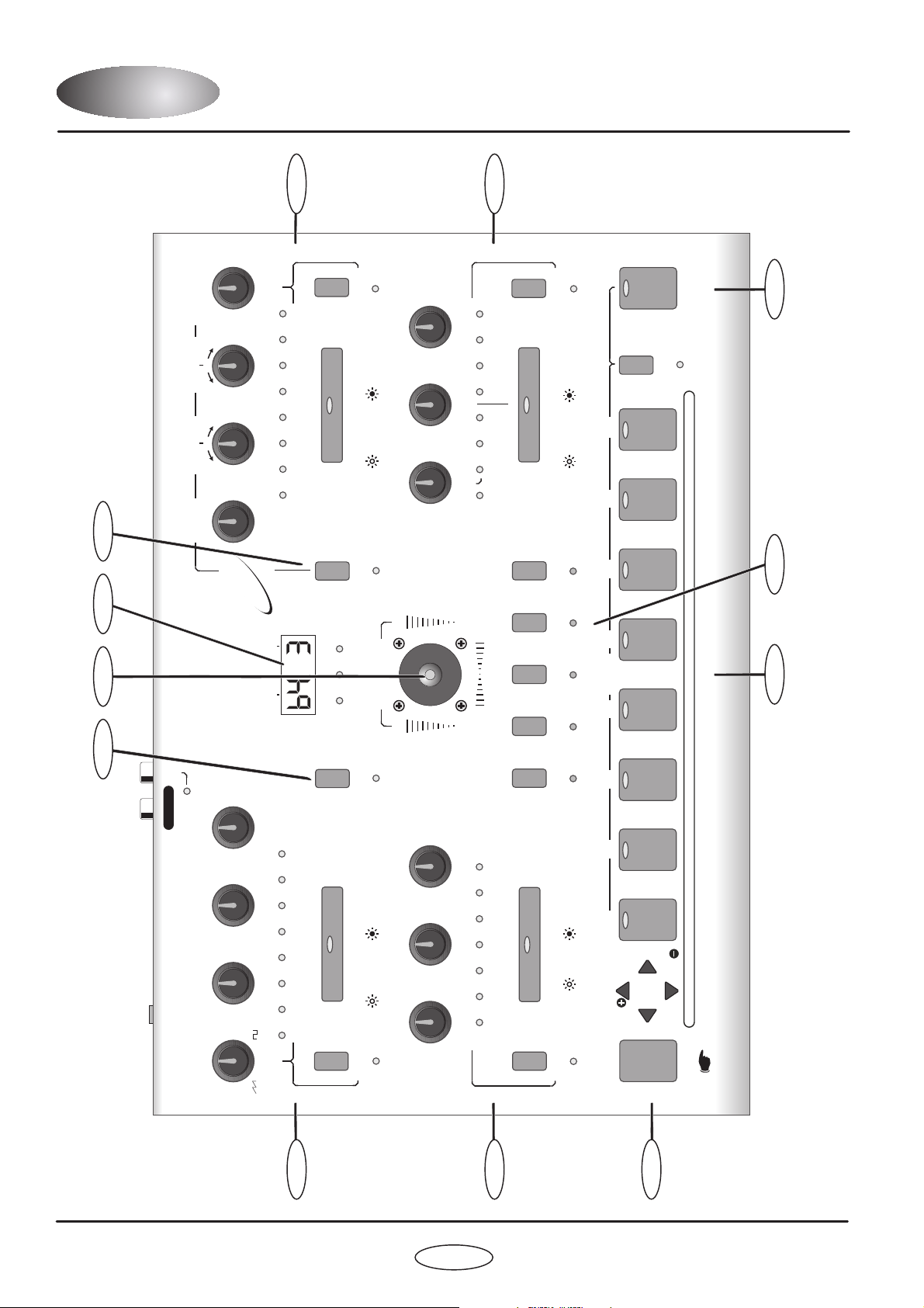
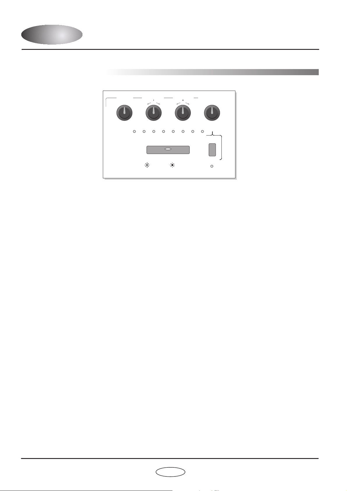
FRONT PANELFRONT PANEL
8
1
3
OUTPUT
2
4
7
DarkStar Synthesizer
PARAMETER
AUDITION
PROGRAM
BANK
MIXER
4321
87
FILTER TYPE RES MOD SOURCE
PULSE
ENV1 ENV2
SINE
HI
SAMPLE
LFO1
RANDOM
LFO2
SQUARE
BAND
TRI
LO
RAMP
OFF
UTILITY
DELAY
RESONANCE
SPEED
FREQUENCY
(RES MOD)(FILTER TYPE)
(LFO 2 MOD)
(MIDI CLOCK)
SHAPE
ENV MOD
Envelope 1
LFO1
(SHIFT)
Envelopes
Filter
(SHIFT)
Max
Max
Max
Max
LFO’s
LEVEL
EXT.
INPUT
(SHIFT)
EDIT
21
MENU
PROG
Envelope 2
LFO2
Filter Off Filter On
DOWN
MENU
VALUE
VALUE
MENU
UP
(SHIFT)
Min
Min
Min
Min
OSC 2 SEMITONE OFFSET
1716 19 24
12750
PITCH MODWAVEFORM
DETUNEPULSE WIDTH
Oscillators
Oscillator 1
Oscillator2
VELOCITY LEVEL
54 6 7
3210
DECAYATTACK
RELEASESUSTAIN
MaxMaxMax
Max
MinMinMin
Min
PART SELECT
DarkStarDarkStar
8 VOICE POLYPHONIC SYNTHESIZER
OSC 1 OSC 2
MODULATION
Max
Min
RING
OSCILLATORSEDIT
MODULATIONMIDI
LFOOUTPUTFILTER
3
65
BANK PROG
54
PORTA/TRIGGERPART
/VALUE
11 10
6 5
12
(PWM)
MaxMin
(OSC 2 PITCH)
0 0
Max+10
+2
Semitones
-2
Semitones
-10
www.redsound.com
RED
LFO SHAPE
0
+10-10
(0)
(+10)(-10)
(VELOCITY)
PART
OUTPUT
9
PANNINGLEVEL
PORTAMENTOTREMOLO
OffOff
-- ++

1.
2.
3.
4.
5.
6.
7.
8.
9.
10.
11.
12.
OSCILLATORS:
ENVELOPES:
LFO’S:
FILTER:
PART SELECT:
MENU:
AUDITION:
PROGRAM:
PART OUTPUT:
PARAMETER/VALUE DISPLAY:
MIXER:
UTILITY:
This section features [WAVEFORM], [PITCH MOD], [PULSE WIDTH] and [DETUNE] controls
for each oscillator. The large [OSCILLATOR] button switches between oscillators1&2.The[SHIFT] button is used
to access the [OSC 2 PITCH] and [PWM] controls in the oscillator sub-menu.
This section features [ATTACK], [DECAY], [SUSTAIN] and [RELEASE] controls for each
envelope. The large [ENVELOPE] button switches between envelopes1&2.The[SHIFT] button is used to access
the [VELOCITY] control in the envelope sub-menu.
This section features [SPEED], [DELAY] and [SHAPE] controls for each LFO. The large [LFO] button
switches between LFO1&2.The[SHIFT] button is used to access the [MIDI CLOCK] control in the LFO submenu.
This section features [FREQUENCY], [RESONANCE] and [ENV MOD] controls for the filter. The large
[FILTER] button switches the filter on and off. The [SHIFT] button is used to access the [FILTER TYPE], [RES MOD]
and [LFO 2 MOD] controls in the oscillator sub-menu.
These buttons are used to select the 5 Multitimbral ‘PARTS’. You can create and store 5 totally
different sounds in each program.
This section features 8 menu buttons and a 4-way keypad. The MENU buttons are used to select
additional parameters for editing whilst the [EDIT] keypad is used to scroll up and down the menu and change the
values.
This button can be used to trigger the currently selected PART.
This section features the [PROGRAM] and [BANK] buttons which are used to select the 8 banks of
8 programs (total programs = 64).
This button is used to access the [LEVEL], [PANNING], [TREMOLO] and [PORTAMENTO]
parameters for each individual PART.
This 4-digit LED display shows bank/program numbers, parameter
information and edit values.
The joystick mixer adjusts the balance between OSCILLATORS 1 and 2 (or external input) and also
sets the amount of RING MODULATION.
This button is used to access the SYSTEM EXCLUSIVE utility parameters.
FRONT PANEL FEATURESFRONT PANEL FEATURES
3
FRONT PANEL FEATURES
OWNERS MANUAL
1 2 3 4 5
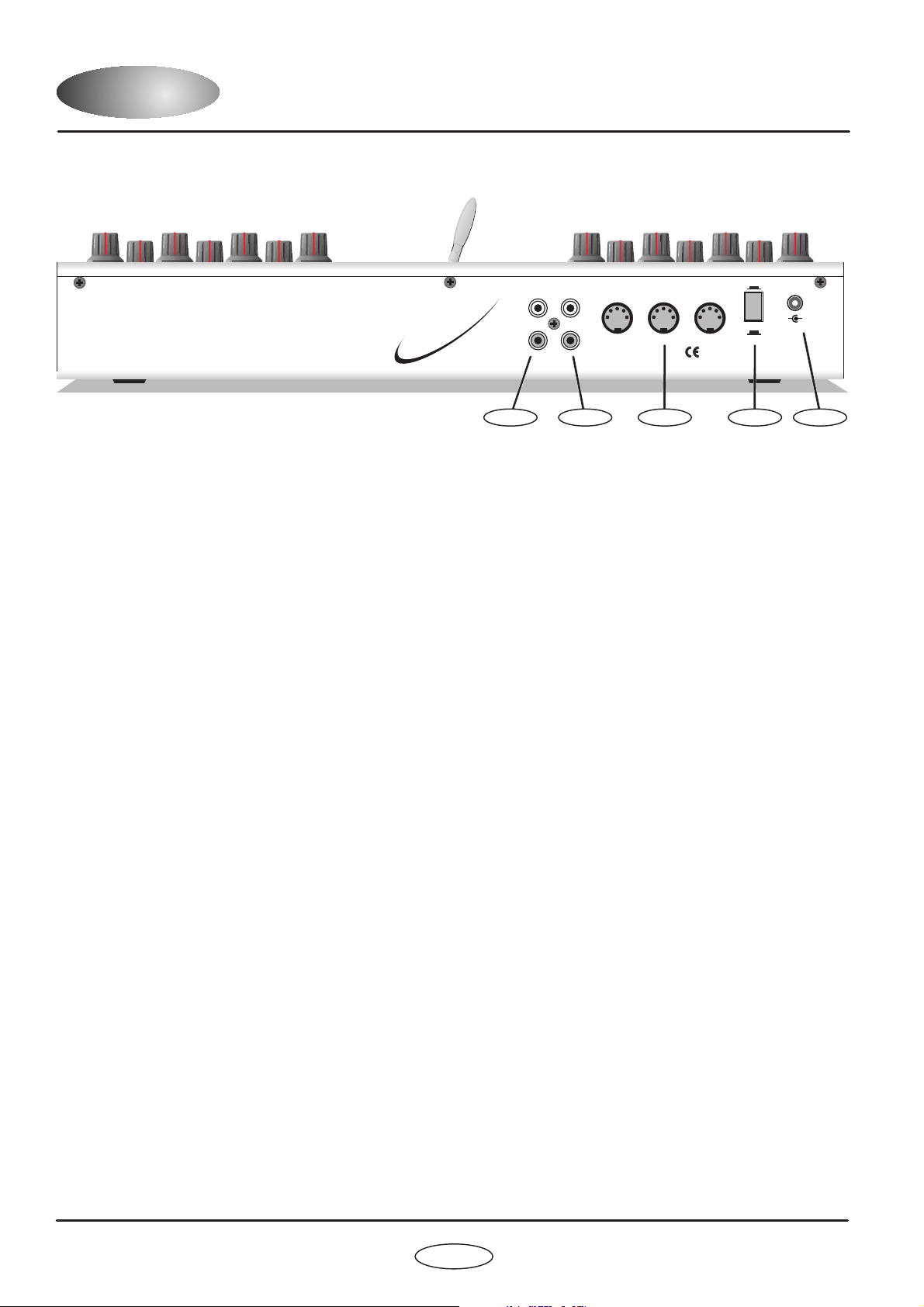
1.
2.
3.
4.
5.
EXTERNAL INPUTS 1&2 - RCA Phono Connectors
STEREO OUTPUT - RCA Phono Connectors
MIDI IN/OUT/THRU - Connectors
POWER - Switch
DC POWER IN - Connector
Use these sockets to connect any external line level sound sources to DARKSTAR for filter/envelope processing.
Use these sockets to connect DARKSTAR to your mixing desk or amplification system.
MIDI data will be transmitted and received by these connectors.
This turns the power on and off.
Only use the 9vDC 800 mA PSU supplied with DARKSTAR to power the unit.
REAR PANELREAR PANEL
4
DarkStar Synthesizer
MIDI
OUT INTHRU
MADE IN ENGLAND
OUTEXT.
INPUT
1 L
2 R
POWER
9v DCOFF
ON
CAUTION: DO NOT OPEN CASE
REFER TO QUALIFIED SERVICE PERSONNEL
NO USER SERVICEABLE PARTSINSIDE
DarkStarDarkStar
www.redsound.com
RED
8 VOICE POLYPHONIC SYNTHESIZER
+
-
RED Sound Systems Ltd

5
OWNERS MANUAL
CONNECTIONSCONNECTIONS
MIDI
OUT INTHRU
MADE IN ENGLAND
OUTEXT.
INPUT
1 L
2 R
POWER
9v DCOFF
ON
CAUTION: DO NOT OPEN CASE
REFER TO QUALIFIED SERVICE PERSONNEL
NO USER SERVICEABLE PARTSINSIDE
DarkStarDarkStar
www.redsound.com
RED
8 VOICE POLYPHONIC SYNTHESIZER
+
-
RED Sound Systems Ltd
MIDI IN
MIDI IN
MIDI OUT
MIDI SEQUENCER
MIDI KEYBOARD
OTHER MIDI DEVICE
STUDIO MIXING DESK
EXTERNAL MIDI DRIVEN SOUND SOURCE 1
EXTERNAL MIDI DRIVEN SOUND SOURCE 2
RL
TO
AC WALL
SOCKET
RED PSU

QUICK START
GETTING STARTED
If you want to quickly try out the performance of DARKSTAR, please read the following points carefully:
Before making any connections, make sure that the power on all your equipment is turned OFF.
Connect the power supply (included) to the ‘power in’ socket on the rear panel of DARKSTAR and plug it into a
suitable AC outlet. Connect the audio cables for a basic system setup as shown on page 5.
Make sure all connections have been made correctly and the volume controls on the
mixing desk and amplifier system are turned completely down. Press the rear panel power switch on DARKSTAR.
Turn on the power of the mixing desk and then turn on the power of the amplifier system.
When DARKSTAR is powered up, the main display will show the software version
whilst various parameters are being set internally. When this process is complete, the display will show the BANK
and PROGRAM number. If this does not happen, check the power supply is of the correct type and the unit was
switched on correctly.
To select the correct MIDI receive channel press the [MIDI] MENU
button and use the [EDIT] keypad [VALUE +] and [VALUE -] buttons to set the channel of the active PART (as
DARKSTAR can have up to 5 different sounds/MIDI channels setup in each PROGRAM you may have to change
the MIDI transmit channel on your keyboard a few times to play all the sounds).
To select the factory programs in BANK 1, press and hold the [PROGRAM] button
(LED on) and then press one of the buttons marked 1-8. To select one of the other 7 banks of 8 programs press
and hold the [PROGRAM] button then press the [BANK] button. Now you can select one of the 8 programs in the
new bank using the buttons marked 1-8 (
).
Use the [AUDITION] button or connected MIDI keyboard to trigger the sounds. You can modify the sounds in realtime by altering the controls in the OSCILLATOR, FILTER, ENVELOPE and LFO sections.
Please read the following “OPERATION” section carefully to fully appreciate the range of features and facilities the
DARKSTAR 8-Voice Synthesizer has to offer.
After connecting DARKSTAR to your system as detailed on page 5, press in the power switch on the rear panel to
turn the power on. As the software is initialising (takes approximately 12 seconds) rows of indicators will light in
sequence and the version number fitted to your unit will be shown on the main display:
Afterwards, the last selected program (before power was switched off at the previous session) will be recalled and
displayed as follows:
CONNECTIONS:
TURNING ON THE POWER:
POWER UP INDICATIONS:
SETTING THE MIDI RECEIVE CHANNEL:
SELECTING A PROGRAM:
keep your finger on the [PROGRAM] button at all times when selecting
programs/banks
NOTE: Banks 1 to 6 (48 programs) feature factory presets that demonstrate the sonic power of DARKSTAR.
Programs in banks 7 and 8 all contain the same basic sound ready for you to overwrite with newly created sounds.
QUICK STARTQUICK START
6
DarkStar Synthesizer
PARAMETER
VALUE
PARAMETER
VALUE
Software version = 1.01
Bank 4
Program 6
BANK
BANK
PROG
PROG
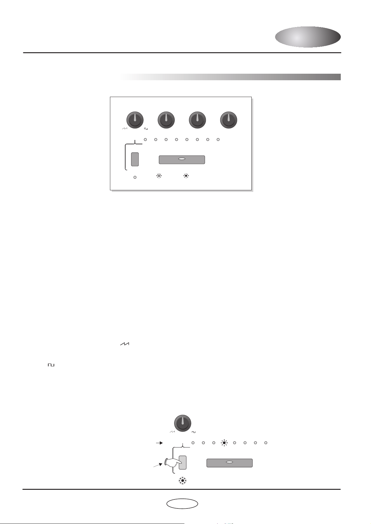
OSCILLATOR SECTION
OSCILLATOR SELECT button
WAVEFORM
This section of DARKSTAR produces the musical tones which form the basis of subtractive synthesis. There are
two oscillators per ‘voice’ (musical note), each producing audible vibrations to act as a sound source. The timbre of
each oscillator depends on its harmonic content which is determined by the waveform. There are basically two
waveforms available, SAWTOOTH and RISING, each with its own specific set of harmonics.
Controls for changing the amount of modulation to the pitch timbre of the oscillators are also included in this
section. These timbral and pitch modulations give the oscillator sound more depth and stimulate musical appeal to
the ear.
This large button switches between oscillator 1 and 2. When the indicator is OFF, oscillator 1 will be selected.
When the indicator is ON, oscillator 2 will be selected.
This control has two functions determined by the [SHIFT] button.
When the [SHIFT] function is (SHIFT LED Off) this control sets the selected oscillator’s waveform.
At the fully anti-clockwise position ( ) the waveform will be shaped like a SAWTOOTH. This waveform contains
every harmonic in decreasing volume and produces a very rich sound. As the control is moved in a clockwise
direction the shape progressively changes, becoming more and more ‘squared-off’ until, at the fully clockwise
position ( ) the shape will be a SQUARE or ‘pulse’ waveform. As a pure square wave (max and min values equal)
the harmonic content will be all the odd-numbered harmonics in decreasing volume which gives the sound a hollow
or ‘woody’ timbre. The width of the pulse can also be altered by the [PULSE WIDTH] knob to make the sound
thinner.
When the [SHIFT] function is selected (SHIFT LED Flashing) this control sets the amount of oscillator 2 pitch
offset. This detune setting is calibrated in semitones with the eight indicators labelled [OSC 2 SEMITONE OFFSET]
showing the value, as in the following example:
(OSC 2 PITCH)
NOT selected ,
,
7
OWNERS MANUAL
OPERATIONOPERATION
(SHIFT)
(SHIFT)
OSC 2 SEMITONE OFFSET
OSC 2 SEMITONE OFFSET
17
17
16
16
191924
24
121277550
00
Oscillators
Oscillators
Oscillator 1
Oscillator2
Example:
Oscillator 2 pitch offset =
12 semitones (1 octave)
WAVEFORM
(OSC 2 PITCH)
PITCH MODWAVEFORM DETUNEPULSE WIDTH
(PWM)
MaxMin
(OSC 2 PITCH)
0 0
+10
+2
Semitones
-2
Semitones
-10
Press once
before changing
the setting
8
OPERATIONOPERATION
PITCH MOD
PULSE WIDTH
DETUNE
OSCILLATOR MENU
(PWM)
This control has two functions determined by the [SHIFT] button.
When the [SHIFT] function is (SHIFT LED Off) this control sets the amount of pitch modulation to
the selected oscillator. At the 12 o’clock position there will be no pitch modulation applied. As the knob is moved in
an anti-clockwise direction the pitch modulation will become negative, first falling then rising. At the fully anticlockwise position the modulation will be at its maximum negative depth. As the knob is moved in a clockwise
direction from the centre position, the pitch modulation will become positive, first rising then falling. At the fully
clockwise position the modulation will be at its maximum positive depth. See [OSCILLATOR] menu section below
for further details on the pitch modulation source.
When the [SHIFT] function is selected (SHIFT LED Flashing) this control sets the amount of pulse width
modulation or PWM for the selected oscillator when its [WAVEFORM] is set to SQUARE ( ). The PWM
SOURCE can be set to LFO1, LFO2, ENV1 or ENV2 (see [OSCILLATOR] menu) with negative and positive
modulations available. At the 12 o’clock position there will be no PWM. As the knob is moved in an anti-clockwise
direction the variation in the pulse width will become more and more pronounced in a negative manner.Asthe
knob is moved in a clockwise direction the variation in the pulse width will become more and more pronounced in a
positive manner.
This control sets the actual width of the pulse. At the fully anti-clockwise position the fundamental will be at its
minimum producing an extremely thin sound. As the knob is moved in a clockwise direction the pulse width gets
wider, with progressively less high harmonics being added giving the sound a fuller timbre. At the fully clockwise
position the minimum and maximum values of the pulse width will be equal.
This control sets the fine tuning for each oscillator. At the 12 o’clock position the oscillators tuning will be
unaffected. As the knob is moved in an anti-clockwise direction the oscillators tuning will become more ‘Flat’, with a
total negative detune of - 2 semitones available at the fully anti-clockwise position. As the knob is moved in a
clockwise direction the oscillators tuning will become more ‘Sharp’, with a total positive detune of + 2 semitones
available at the fully clockwise position. Small variations in the oscillators relative tuning will fatten up a sound
giving it a rich texture. Larger amounts of detuning create a more extreme effect.
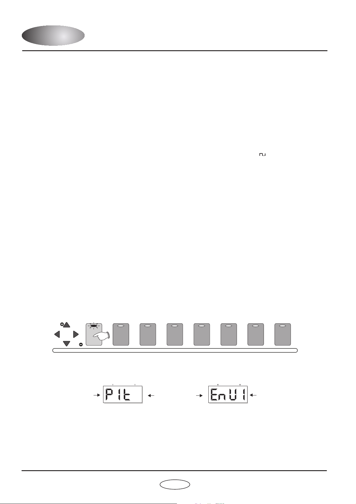
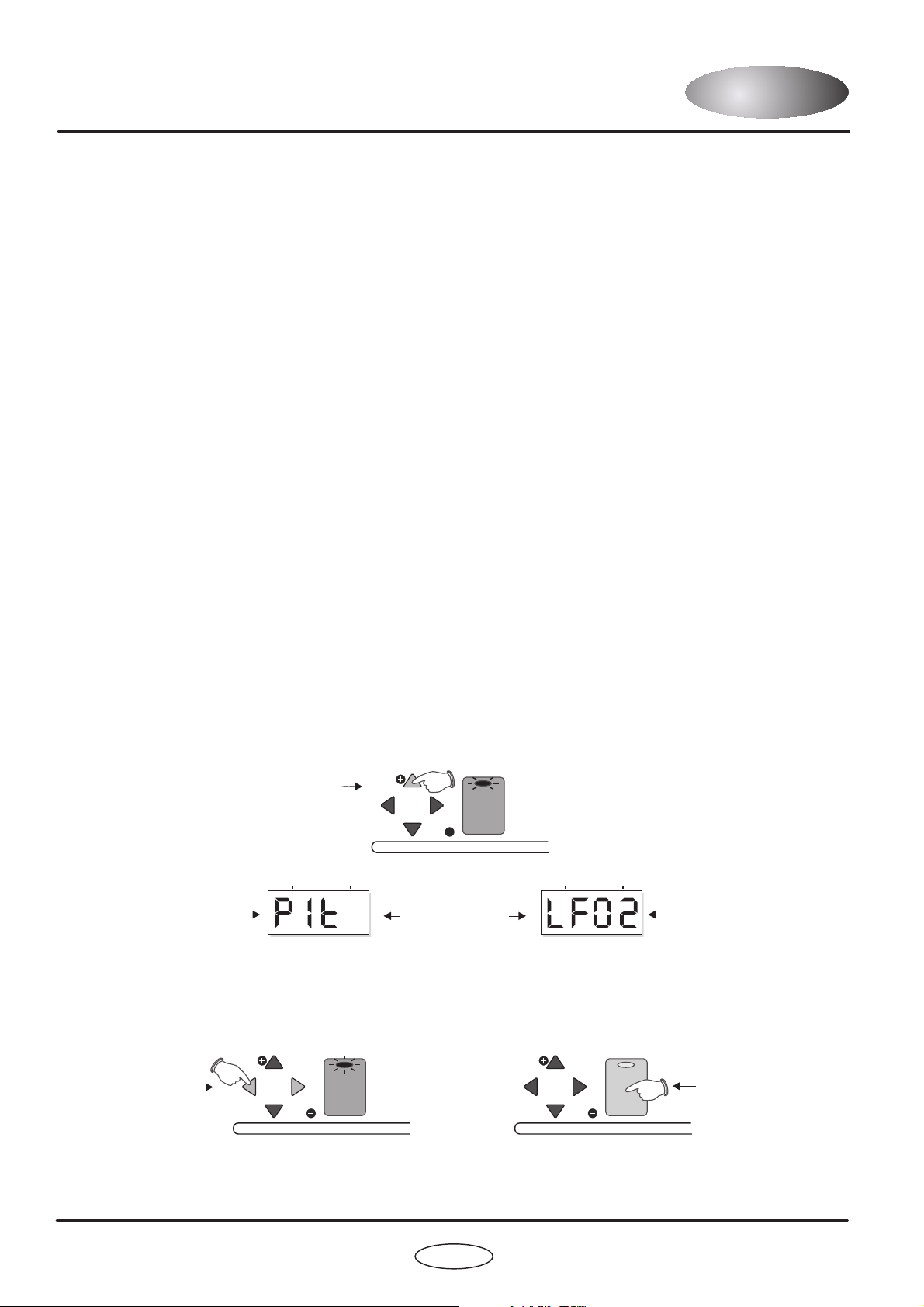
This section contains the remaining functions for the oscillators. To access these settings, press the MENU button
labelled [OSCILLATORS], as shown in the following example:
The indicator in the [OSCILLATOR] button will light and the main display will now alternate between the first
function and its current value, as shown below:
There are 4 functions in the oscillator menu with multiple settings as detailed in the following paragraphs.
This function allows you to derive the selected oscillator’s PITCH modulation from
one of four different sources. The selections are:
NOT selected ,
,
1. Pitch Modulation Source:
DarkStar Synthesizer
MENU
DOWN
MENU
VALUE
VALUE
MENU
UP
OSCILLATORSEDIT MODULATIONMIDILFOOUTPUTFILTER PORTA/TRIGGERPART
PARAMETER
VALUE
PARAMETER
VALUE
First selection =
Envelope 1
Function =
Pitch Modulation
source
BANK BANKPROG PROG
Display alternates
between
9
OWNERS MANUAL
OPERATIONOPERATION
Envelope1 Envelope 2 LFO1 LFO2 -
2. Pulse Width Modulation source:
Envelope1 Envelope 2 LFO1 LFO2 -
3. Oscillator 2 source:
Type 1(normal oscillator) Type 2(Formant style oscillator) Noise1(Pink) Noise 2(White) Noise 3(Blue) External Input1&2 -
4. Oscillator Sync:
The settings of envelope 1 controls will affect the oscillators pitch.
The settings of envelope 2 controls will affect the oscillators pitch.
The settings of the LFO1 controls will affect the oscillators pitch.
The settings of the LFO2 controls will affect the oscillators pitch.
This function allows you to link the selected oscillator’s PULSE WIDTH
modulation to one of four different sources. The selections are:
The settings of envelope 1 controls will affect the oscillators pulse width modulation.
The settings of envelope 2 controls will affect the oscillators pulse width modulation.
The settings of the LFO1 controls will affect the oscillators pulse width modulation.
The settings of the LFO2 controls will affect the oscillators pulse width modulation.
This function allows you to select the sound source for OSCILLATOR 2. The selections are:
This oscillator contains the full range of frequencies.
This oscillator is formed from a limited band of frequencies.
PINK noise has the higher frequencies reduced.
WHITE noise and has all frequencies at an equal level.
BLUE noise has the lower frequencies reduced.
You can switch off all the internal sound generators for oscillator 2 and instead use the rear
panel connectors marked [EXTERNAL INPUTS1-2]toprocess any MIDI driven external sound source through the
filter and envelope sections. See page 29 for further details.
This function synchronises oscillator 2 with oscillator 1. The oscillator 2 waveform will now
restart its cycle each time oscillator 1 starts its own cycle. The result of this keeps the pitch of both oscillators
identical making a distinct change to the timbre. For the best results use envelope 2 to try and move the pitch of
oscillator 2. The pitch cannot change but you will hear timbral changes to the sound with vocal characteristics.
The selections are: ON and OFF.
To change the current oscillator menu setting, use the [EDIT] keypad [VALUE +] and [VALUE - ] buttons as shown in
the following example:
To select a different menu function, use the [MENU DOWN and [MENU UP] buttons. To EXIT oscillator menu mode,
simply press the [OSCILLATOR] MENU button and check that the indicator goes out.
DOWN
DOWN
MENU
MENU
VALUE
VALUE
VALUE
VALUE
MENU
MENU
UP
UP
OSCILLATORS
OSCILLATORS
EDIT
EDIT
PARAMETER
VALUE
PARAMETER
VALUE
New Pitch Mod Source =
LFO2
Press 3 times
to change value
Press once to exit
oscillator menu mode
Function =
Pitch Modulation
source
BANK BANKPROG PROG
Display alternates
between
DOWN
MENU
VALUE
VALUE
MENU
UP
OSCILLATORSEDIT
Press the UP and
DOWN buttons to
select MENU functions
10
OPERATIONOPERATION
DarkStar Synthesizer
ENVELOPE SECTION
ENVELOPE SELECT button
ATTACK
DECAY
SUSTAIN
RELEASE
This section of DARKSTAR is used to shape the sound over a period of time with two envelopes available. The first
envelope is fixed to amplitude (or volume) and decides how quickly the sound starts, sustains and then fades away.
The second envelope can be used to control the filter frequency, pulse width or pitch modulations to alter the
character of the sound.
This large button switches between envelope 1 and 2. When the indicator is OFF, envelope 1 will be selected.
When the indicator is ON, envelope 2 will be selected.
This control sets the time period for the envelope to reach its maximum after a note is played. At the fully anticlockwise position the response is virtually instantaneous giving a percussive edge to the sound. As the knob is
moved in a clockwise direction the time to reach maximum gradually increases giving a softer start to the sound. At
the fully clockwise position the attack time will be at its maximum.
This control sets the rate at which the envelope falls to the [SUSTAIN] level after the maximum [ATTACK] level has
been reached. At the fully anti-clockwise position the response is virtually instantaneous. As the knob is moved in a
clockwise direction the decay duration gradually increases until, at the fully clockwise position the decay time will
be at its maximum.
This control sets the level of the envelope after the decay element is completed and until the note is released. At
the fully anti-clockwise position the envelope will continue to decay to zero without interruption. As the knob is
moved in a clockwise direction the level at which the decay ends gradually increases until, at the fully clockwise
position the sustain level will be at its maximum.
This control has two functions determined by the [SHIFT] button.
When the [SHIFT] function is (SHIFT LED Off) this control sets the time taken for the sustain level to
reach zero once the note has been released. At the fully anti-clockwise position the response is virtually
instantaneous giving an abrupt end to the sound. As the knob is moved in a clockwise direction the release time
gradually increases resulting in a softer, more natural end to the sound. At the fully clockwise position the release
time will be at its maximum.
(VELOCITY)
NOT selected ,
Envelope 1
(SHIFT)
Envelopes
Envelope 2
VELOCITY LEVEL
54 6 73210
DECAYATTACK RELEASESUSTAIN
MaxMaxMax MaxMinMinMin Min
(VELOCITY)
PANNINGLEVEL PORTAMENTOTREMOLO
OffOff
-- ++

11
OWNERS MANUAL
OPERATIONOPERATION
LFO SECTION
LFO SELECT button
SPEED
This section of DARKSTAR features 2 LFOs (Low Frequency Oscillators) which make regular electronic variations,
too low to be heard when converted into audio vibrations. They can be used independently to alter elements of the
sound by adding vibrato or changes to the harmonic content.
This large button switches between LFO1 and 2. When the indicator is OFF, LFO1 will be selected. When the
indicator is ON, LFO2 will be selected.
This control has two functions determined by the [SHIFT] button.
When the [SHIFT] function is (SHIFT LED Off) this control sets the rate of the selected LFO.NOT selected ,
PULSESINE SAMPLE RANDOMSQUARETRIRAMP
DELAYSPEED
(MIDI CLOCK)
SHAPE
LFO1
(SHIFT)
MaxMax
LFO’s
LFO2
MinMin
LFO SHAPE
When the [SHIFT] function is selected (SHIFT LED Flashing) this control sets how much the selected envelope is
affected by the velocity level. Firmly struck notes will open the envelope to its maximum level whilst softer strokes
will produce a lesser result, dependent on the velocity setting. The eight VELOCITY LEVEL indicators show the
velocity setting for the selected envelope. To change the setting, first press the [SHIFT] button and then move the
[VELOCITY] knob. The indicators will show the value, as shown in the following example:
At the fully anti-clockwise position [indicator 0] there will be no velocity effect, with soft and hard notes each
producing the same, maximum result. As the knob is moved in a clockwise direction [indicators 1 to6]the
envelope will open less and less when softer notes are played until, at the fully clockwise position [indicator 7] the
softest notes will not open the envelope at all. On envelope 1 this maximum setting will make soft notes sound very
quiet whilst on envelope 2 this will result in much less pitch, pulse width or filter modulation.
,
(SHIFT)
VELOCITY LEVEL
54 6 73210
RELEASE
MaxMin
(VELOCITY)
Press once
before changing
the setting
Example: Envelope 1 velocity setting = 5
Envelope 1
Envelopes
Envelope 2
 Loading...