

Page 1

Redpine Signals, Inc. Proprietary and Confidential
RS9116 n-Link Linux and Android
TTeecchhnniiccaall RReeffeerreennccee MMaannuuaall
VVeerrssiioonn 22..00
January 2019
Redpine Signals, Inc.
2107 North First Street, #540
San Jose, CA 95131.
Tel: (408) 748-3385
Fax: (408) 705-2019
Email: sales@redpinesignals.com
Website: www.redpinesignals.com
Page 2

Redpine Signals, Inc. Proprietary and Confidential Page 2
RS9116 n-Link Linux and Android
Technical Reference Manual
Version 2.0
Disclaimer:
The information in this document pertains to information related to Redpine Signals, Inc. products. This information is
provided as a service to our customers, and may be used for information purposes only.
Redpine assumes no liabilities or responsibilities for errors or omissions in this document. This document may be changed
at any time at Redpine’s sole discretion without any prior notice to anyone. Redpine is not committed to updating this
document in the future.
Copyright © 2018 Redpine Signals, Inc. All rights reserved.
Page 3

Redpine Signals, Inc. Proprietary and Confidential Page 3
RS9116 n-Link Linux and Android
Technical Reference Manual
Version 2.0
About this Document
This document is a preliminary version of RS9116 n-Link Technical Reference Manual for Linux and Android, provided to
customers under a Non-Disclosure Agreement (NDA).
src-23903865_BluetoothhcitoolandhciconfigUsage-_Toc174878560
Page 4

Redpine Signals, Inc. Proprietary and Confidential Page 4
RS9116 n-Link Linux and Android
Technical Reference Manual
Version 2.0
Table Of Contents
1 Introduction to RS9116 ........................................................................................................... 11
2 Getting Started with RS9116 ................................................................................................... 12
2.1 Hardware Requirements .............................................................................................................. 12
2.2 Software Requirements ............................................................................................................... 12
2.3 Software Package Contents .......................................................................................................... 12
3 Compiling the Driver ............................................................................................................... 13
4 Installing the Driver ................................................................................................................ 18
4.1 Installation of Modules ................................................................................................................ 18
4.2 Enabling a Protocol ...................................................................................................................... 18
4.3 Disabling a Protocol ..................................................................................................................... 19
4.4 OneBox-Mobile in Wi-Fi Only Mode ............................................................................................. 19
4.4.1 Installation in Wi-Fi Client Mode (with BSD interface support) ...................................................................... 19
4.4.2 Installation in Access Point Mode (with BSD interface support) ..................................................................... 23
4.4.3 Installation in Wi-Fi Client Mode (with NL80211 support).............................................................................. 24
4.4.4 Installation in Wi-Fi AP mode (with NL80211 support) ................................................................................... 26
4.4.5 Installation in Wi-Fi Direct Mode (With BSD Interface Support) ..................................................................... 28
4.4.5.1 Autonomous GO Mode ............................................................................................................................... 28
4.4.6 Installation in Wi-Fi Direct Mode (With NL80211 Support only for Kernel v3.8 or higher) ............................ 29
4.4.6.1 Autonomous GO Mode ............................................................................................................................... 29
4.5 OneBox-Mobile in Wi-Fi + Bluetooth Classic Coexistence Mode ..................................................... 30
4.6 OneBox-Mobile in Wi-Fi + Bluetooth LE Coexistence Mode ........................................................... 31
4.6.1 Advertise, Scan, Connect Commands .............................................................................................................. 31
4.7 OneBox-Mobile in Wi-Fi + Bluetooth Classic + Bluetooth LE Coexistence Mode .............................. 32
4.8 OneBox-Mobile in Wi-Fi + ZigBee Coexistence Mode ..................................................................... 34
4.8.1 Building and Running the Sample Home Automation Switch Application ...................................................... 34
4.8.1.1 About the Sample Application..................................................................................................................... 35
4.8.1.2 Host API Folder Structure ............................................................................................................................ 35
4.8.1.3 Building and Running the Home Automation Sample Application ............................................................. 35
4.9 Driver Uninstallation Procedure ................................................................................................... 35
4.10 Driver Information .................................................................................................................... 35
4.10.1 Driver Statistics ............................................................................................................................................... 35
4.10.2 Disabling Driver Debug Prints .......................................................................................................................... 36
5 Wi-Fi ioctl Usage Guide ........................................................................................................... 37
5.1 Configuring using Wireless Extensions .......................................................................................... 37
5.2 Private (Driver-Specific) Commands for Access Point and Client Modes ......................................... 39
5.3 Private (Driver- Specific) Commands for Access Point Mode .......................................................... 41
5.4 Private (Driver- Specific) Commands for Client Mode .................................................................... 45
5.5 Configuring Using onebox_util ...................................................................................................... 45
5.5.1 WPS Configuration .......................................................................................................................................... 56
5.5.1.1 Access Point Mode ...................................................................................................................................... 57
5.5.1.2 Client Mode ................................................................................................................................................. 58
6 Configuration Using CFG80211 ................................................................................................ 59
6.1 Using iw Wireless Tool ................................................................................................................. 59
7 Enterprise security using CFG80211 ........................................................................................ 62
7.1 Installation and configuration of FREERADIUS Server .................................................................... 62
Page 5

Redpine Signals, Inc. Proprietary and Confidential Page 5
RS9116 n-Link Linux and Android
Technical Reference Manual
Version 2.0
7.2 Configuration of AP and RADIUS server to use EAP methods ......................................................... 63
7.2.1 Configuration of the AP ................................................................................................................................... 64
7.2.2 Configuring hostapd as RADIUS server ........................................................................................................... 65
7.2.3 Configuring Station to connect to an EAP enabled AP. ................................................................................... 66
8 HOSTAPD and Wi-Fi Protected Setup (WPS) ............................................................................ 69
8.1 Hostapd Configuration before Compilation ................................................................................... 69
8.2 Configuration in hostapd_ccmp.conf ............................................................................................ 69
8.3 WPS ............................................................................................................................................. 70
8.3.1 AP-mode for WPS -push button method ........................................................................................................ 70
8.3.2 AP-mode for WPS Enter-pin method .............................................................................................................. 70
8.3.3 AP-mode for WPS-Generate pin- method ....................................................................................................... 71
8.3.4 Disable AP pin .................................................................................................................................................. 71
8.3.5 Get the AP pin ................................................................................................................................................. 71
8.3.6 Set the AP pin .................................................................................................................................................. 72
8.3.7 Get the current configuration ......................................................................................................................... 72
9 ACS with Hostapd ................................................................................................................... 73
10 Antenna Diversity ................................................................................................................ 74
10.1 Introduction ............................................................................................................................. 74
10.2 Configuration ........................................................................................................................... 74
11 Sniffer Mode ....................................................................................................................... 75
12 Monitor Mode ..................................................................................................................... 76
13 Concurrent Mode ................................................................................................................ 77
13.1 Installation Procedure .............................................................................................................. 77
13.1.1 Creating VAP in Client Mode ........................................................................................................................... 77
13.1.2 Creating VAP in AP mode ................................................................................................................................ 78
13.1.3 State of the Station ......................................................................................................................................... 79
14 Background Scan Parameters .............................................................................................. 82
15 Power save Modes, Profiles and Parameters ........................................................................ 83
15.1 Power save Modes ................................................................................................................... 83
15.2 Power save Profiles .................................................................................................................. 83
15.3 Wakeup Procedures and Data Retrieval .................................................................................... 83
15.4 Power save Parameters ............................................................................................................ 84
15.5 Procedure to enable device power save for USB interface.......................................................... 85
16 Compliance and Certification ............................................................................................... 87
16.1 Federal Communication Commission Statement ........................................................................ 87
16.1.1 Labeling and User Information ◆ This device complies with part 15 of the FCC Rules. Operation is subject to
the following two conditions: (1) This device may not cause harmful interference, and (2) this device must
accept any interference received, including interference that may cause undesired operation. ◆ RF exposure
statements 1. This Transmitter must not be co‐located or operating in conjunction with any other antenna or
transmitter. 2. This equipment complies with FCC RF radiation exposure limits set forth for an uncontrolled
environment. This equipment should be installed and operated with a minimum distance of 20 centimeters between
the radiator and your body or nearby persons. ◆ For a host using a certified modular with a standard fixed label, if
(1) the module’s FCC ID is not visible when installed in the host, or (2) if the host is marketed so that end users do not
have straightforward commonly used methods for access to remove the module so that the FCC ID of the module is
visible; then an additional permanent label referring to the enclosed module:“Contains Transmitter Module FCC ID:
XF6-M7DB6” or “Contains FCC ID: XF6-M7DB6” must be used. The host OEM user manual must also contain clear
instructions on how end users can find and/or access the module and the FCC ID. ...................................................... 87
16.2 Industry Canada / ISED Statement............................................................................................. 88
Page 6

Redpine Signals, Inc. Proprietary and Confidential Page 6
RS9116 n-Link Linux and Android
Technical Reference Manual
Version 2.0
16.2.1 Labeling and User Information ........................................................................................................................ 89
17 Wi-Fi Performance Test ioctl usage ...................................................................................... 90
17.1 WiFi Transmit Tests .................................................................................................................. 90
17.1.1 Transmit Command Usage .............................................................................................................................. 90
17.2 Wi-Fi Receive Tests ................................................................................................................... 94
17.2.1 Receive Command Usage ................................................................................................................................ 94
17.3 Continuous Wave (CW) mode ................................................................................................... 95
17.3.1 Command Usage ............................................................................................................................................. 95
18 Wake-On-Wireless LAN ....................................................................................................... 97
18.1 WoWLAN through onebox_util ................................................................................................. 97
18.2 WoWLAN using Linux power state machine ............................................................................... 97
18.2.1 Overview ......................................................................................................................................................... 97
18.2.2 Configure WoWLAN ........................................................................................................................................ 98
18.3 Suspend system ........................................................................................................................ 99
18.4 Trigger wakeup ......................................................................................................................... 99
19 PUF [ Physical Unclonable Functions ] ................................................................................ 100
19.1 Introduction ............................................................................................................................ 100
19.2 Configuration .......................................................................................................................... 100
19.3 PUF Operations and IOCTL Usage ............................................................................................. 100
19.3.1 PUF Enroll ...................................................................................................................................................... 100
19.3.2 PUF Start ....................................................................................................................................................... 100
19.3.3 PUF Set Key ................................................................................................................................................... 100
19.3.4 PUF Set Intrinsic Key ...................................................................................................................................... 100
19.3.5 PUF Get Key ................................................................................................................................................... 100
19.3.6 PUF Load Key ................................................................................................................................................. 101
19.3.7 PUF AES Encryption ....................................................................................................................................... 101
19.3.8 PUF AES Decryption....................................................................................................................................... 101
19.3.9 PUF AES MAC Generation ............................................................................................................................. 101
19.3.10 PUF Block Enroll ........................................................................................................................................ 101
19.3.11 PUF Block Set Key ...................................................................................................................................... 101
19.3.12 PUF Block Get Key ..................................................................................................................................... 102
20 GTK Offload ....................................................................................................................... 103
20.1 Configuration .......................................................................................................................... 103
21 Steps to connect 802.11R client to AP ................................................................................ 104
22 Steps to configure 802.11W ............................................................................................... 105
22.1 Configuring and Compiling Driver for PMF in client mode: ........................................................ 105
22.2 Configuring and Compiling Driver for PMF in AP mode:............................................................. 105
23 Bluetooth hcitool and hciconfig Usage ............................................................................... 106
23.1 Bluetooth Power Save Commands ........................................................................................... 107
23.2 Bluetooth Performance Test ioctl Usage ................................................................................... 107
23.3 BT CLASSIC Transmit ................................................................................................................ 108
23.3.1 IOCTL ............................................................................................................................................................. 108
23.3.2 Description .................................................................................................................................................... 108
23.3.3 Appendix ....................................................................................................................................................... 109
23.4 BT Classic Receive .................................................................................................................... 112
23.4.1 Introduction .................................................................................................................................................. 112
23.4.2 IOCTL ............................................................................................................................................................. 112
23.4.3 Description .................................................................................................................................................... 113
Page 7

Redpine Signals, Inc. Proprietary and Confidential Page 7
RS9116 n-Link Linux and Android
Technical Reference Manual
Version 2.0
23.4.4 Appendix ....................................................................................................................................................... 113
23.5 BLE/BLR Transmit .................................................................................................................... 114
23.5.1 Introduction .................................................................................................................................................. 114
23.5.2 IOCTL ............................................................................................................................................................. 114
23.5.3 Description .................................................................................................................................................... 114
23.5.4 Appendix ....................................................................................................................................................... 115
23.6 BLE/BLR Receive ...................................................................................................................... 116
23.6.1 Introduction .................................................................................................................................................. 116
23.6.2 IOCTL ............................................................................................................................................................. 117
23.6.3 Description .................................................................................................................................................... 117
23.6.4 Appendix ....................................................................................................................................................... 117
23.7 Hopping .................................................................................................................................. 118
23.7.1 Introduction .................................................................................................................................................. 118
23.7.2 IOCTL ............................................................................................................................................................. 118
23.7.3 Description .................................................................................................................................................... 118
23.7.4 Appendix ....................................................................................................................................................... 118
24 ZigBee Performance Test Application Usage ...................................................................... 120
24.1 ZigBee Transmit Tests .............................................................................................................. 120
24.2 Receive Tests ........................................................................................................................... 120
24.3 Continuous Wave Transmit Mode ............................................................................................ 121
25 Android support for RS9116............................................................................................... 123
26 Appendix A: Configuration of Kernels from 3.13 and above ................................................ 124
26.1 SDIO Stack Options .................................................................................................................. 124
26.2 Wireless Extension Tools.......................................................................................................... 125
26.3 Bluetooth Stack Options .......................................................................................................... 126
26.4 Kernel Compilation .................................................................................................................. 127
27 Appendix B: Binary Files for Embedded Platforms .............................................................. 128
27.1 Common Hardware Requirements for Embedded Platforms ..................................................... 128
27.2 Freescale i.MX6 ....................................................................................................................... 128
27.2.1 Hardware Requirements ............................................................................................................................... 128
27.2.2 Software Requirements ................................................................................................................................ 128
27.2.3 Hardware Setup ............................................................................................................................................ 128
27.2.4 Cross Compile and Copy OneBox-Mobile Software ...................................................................................... 128
27.3 Freescale i.MX53 ..................................................................................................................... 129
27.3.1 Hardware Requirements ............................................................................................................................... 129
27.3.2 Software Requirements ................................................................................................................................ 129
27.3.3 Hardware Setup ............................................................................................................................................ 129
27.3.4 Cross Compile and Copy OneBox-Mobile Software ...................................................................................... 130
27.4 Atmel AT91SAM9G45 and AT91SAM9M10 ............................................................................... 130
27.4.1 Hardware Requirements ............................................................................................................................... 130
27.4.2 Software Requirements ................................................................................................................................ 130
27.4.3 Hardware Setup ............................................................................................................................................ 130
27.4.4 Cross Compile and Copy OneBox-Mobile Software ...................................................................................... 131
28 Appendix C: Using the Bluetooth Manager ......................................................................... 132
29 Appendix D: Common Configuration Parameters ............................................................... 135
29.1 RF Power Mode parameter ...................................................................................................... 135
29.2 Country selection..................................................................................................................... 135
29.3 Antenna selection .................................................................................................................... 135
29.3.1 COEX Mode selection .................................................................................................................................... 136
Page 8

Redpine Signals, Inc. Proprietary and Confidential Page 8
RS9116 n-Link Linux and Android
Technical Reference Manual
Version 2.0
29.3.2 BT RF Type ..................................................................................................................................................... 137
29.3.3 BLE_TX_PWR_INX.......................................................................................................................................... 137
29.3.4 BLE_PWR_SAVE_OPTIONS ............................................................................................................................ 137
30 Appendix E: Installation of Missing Generic Netlink Libraries ............................................. 138
31 Appendix F: Procedure to use latest supplicant with NL80211 interface ............................. 139
31.1 Bgscan and Roaming ................................................................................................................ 139
31.1.1 Description .................................................................................................................................................... 139
31.1.2 Configure Connection quality monitoring (cqm ) rssi and hysteresis using iw command ............................ 140
32 Appendix G: Considerations need to be made during hostapd usage .................................. 141
32.1 Parameters updated from hostapd.conf file ............................................................................. 141
32.2 Paramaeters that will not get updated from hostapd.conf file .................................................. 141
33 RS9116 n-Link Software TRM Revision History ................................................................... 142
Page 9

Redpine Signals, Inc. Proprietary and Confidential Page 9
RS9116 n-Link Linux and Android
Technical Reference Manual
Version 2.0
Table of Figures
No table of figures entries found.
Page 10

Redpine Signals, Inc. Proprietary and Confidential Page 10
RS9116 n-Link Linux and Android
Technical Reference Manual
Version 2.0
Table of Tables
No table of figures entries found.
Page 11

Redpine Signals, Inc. Proprietary and Confidential Page 11
RS9116 n-Link Linux and Android
Technical Reference Manual
Version 2.0
1 Introduction to RS9116
The OneBox-Mobile(refers to single software providing combo of all the features supported) software supports the
following modes. They are outlined below:
• Wi-Fi (Access Point, Client, Wi-Fi-Direct (P2P), Sniffer and Monitor modes)
• Bluetooth Classic
• Bluetooth Low Energy
• ZigBee (Coordinator, Router and End device modes).
The OneBox-Mobile Coexistence software supports the following combination of modes. They are as follows:
• WLAN STATION /WIFI-Direct/WLAN PER
• WLAN ACCESS POINT(including muliple APs on different vaps)
• WLAN ACCESS POINT + STATION MODE(on multiple vaps)
• WAKE ON WIRELESS(WOWLAN)
• BT CLASSIC MODE/BT CLASSIC PER MODE
• WLAN STATION + BT CLASSIC MODE
• WLAN ACCESS POINT + BT CLASSIC MODE
• BT LE MODE /BT LE PER MODE
• WLAN STATION + BT LE MODE
• BT CLASSIC + BT LE MODE
• WLAN STATION + BT CLASSIC MODE + BT LE MODE
• WLAN ACCESS POINT + BT CLASSIC MODE+ BT LE MODE
• ZIGBEE MODE/ ZIGBEE PER MODE
• WLAN STATION + ZIGBEE
• ZIGBEE COORDINATOR MODE
• ZIGBEE ROUTER MODE
The subsequent sections explain the use of OneBox-Mobile software . The installation and operation of the driver on
specific representative processor platforms have been explained in the Appendix sections.
Page 12

Redpine Signals, Inc. Proprietary and Confidential Page 12
RS9116 n-Link Linux and Android
Technical Reference Manual
Version 2.0
2 Getting Started with RS9116
This section lists the hardware and software requirements for the installation of the software and also describes the steps
to be followed to initialize and run the software.
2.1 Hardware Requirements
The Hardware requirements are as follows:
• RS9116N n-Link® Module
• Laptop/PC with SDIO or USB interface or any embedded platform with Linux Board support package.
If the Laptop/PC does not have an SDIO slot, a SDHC/SD/MMC to CardBus Adapter like the one available at
http://www.hwtools.net/cardreader/SDCBA_C01.html can be used.
2.2 Software Requirements
The Software requirements are as follows:
• Linux with kernel version from 2.6.38 to 4.18.5 – should enable the open source SDIO and USB stacks.
• DHCP Server (for Wi-Fi Access Point mode)
• Bluetooth supported commands bluetoothctl and bluetoothd must be present.
• Compatible Bluetooth Host Stack, e.g., the Open Source BlueZ Stack v4.101
• ncurses and ncurses-devel libraries
For kernel versions 3.13 and above, refer to the section on Appendix A: Configuration of Kernels from 3.13 and
above to ensure correct kernel configuration.
2.3 Software Package Contents
The OneBox-Mobile Software is delivered as a tarball with a filename in the format: RS9116.NXX.NL.GEN.LNX.x.y.z.tgz,
where the naming convention is as follows:
NXX – defines whether the package supports only Wi-Fi (N00) or Bluetooth Classic/Low Energy along with Wi-Fi (NB0) or
ZigBee along with Wi-Fi (N0Z) or Bluetooth Classic/Low Energy and ZigBee along with Wi-Fi (NBZ).
x.y.z – identifies the software package.
Redpine driver comes in proprietary and open source form.The Linux driver package contains the following files/folders:
• Readme_nLink.txt
• Releasenotes_nLink.txt
• Documents
• Binary_files (optional)
• source (optional)
Based on the Software License Agreement, driver source code will be available for the users from
"https://www.redpinenetworks.us/OpenKM/login.jsp"
Page 13

Redpine Signals, Inc. Proprietary and Confidential Page 13
RS9116 n-Link Linux and Android
Technical Reference Manual
Version 2.0
3 Compiling the Driver
This section describes the steps to be followed in order to compile the OneBox-Mobile Linux software for different
platforms. The steps are outlined below:
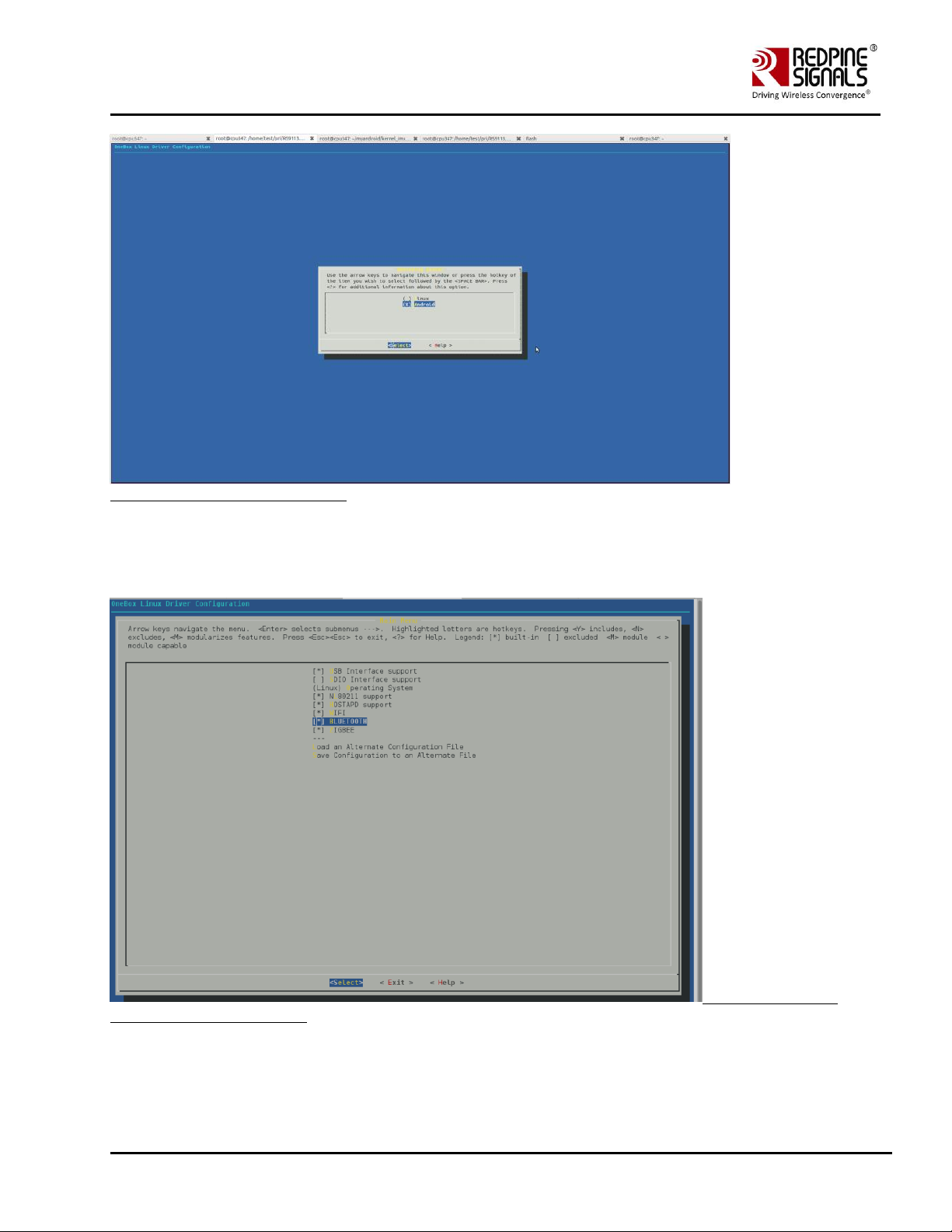
1. Save the required configuration of Driver using the menuconfig utility.
Following are the options available in menuconfig:
• Host Interface: SDIO or USB.
• Operating system: Linux or Android
• Nl80211 support
• Hostapd Support
• WIFI
• BLUETOOTH
• ZIGBEE
2. To open menuconfig utility, untar the tar ball, go to source->host folder & enter the given below command.
make menuconfig
The following images show the menuconfig utility options.
Figure 1: Main Page of menuconfig
Page 14
Redpine Signals, Inc. Proprietary and Confidential Page 14
RS9116 n-Link Linux and Android
Technical Reference Manual
Version 2.0
Figure 2: Selecting Operating System
By default, the driver package includes "BSD" support. In case the user needs "Nl80211" support for Access point and
Station modes, select the menuconfig accordingly. For Nl80211, the "Hostapd" application is used as a configuration
utility.
Figure 3: Selection of
NL80211 and Hostapd Support
Page 15
Redpine Signals, Inc. Proprietary and Confidential Page 15
RS9116 n-Link Linux and Android
Technical Reference Manual
Version 2.0
If NL80211 support is enabled in the driver, make sure that the following modules are loaded in the kernel before
running the driver in order to avoid module dependencies. This can be verified by using the commands.
# lsmod | grep cfg80211
# lsmod | grep bluetooth
If they are not installed, can be installed by using the commands below :
# modprobe cfg80211
# modprobe bluetooth
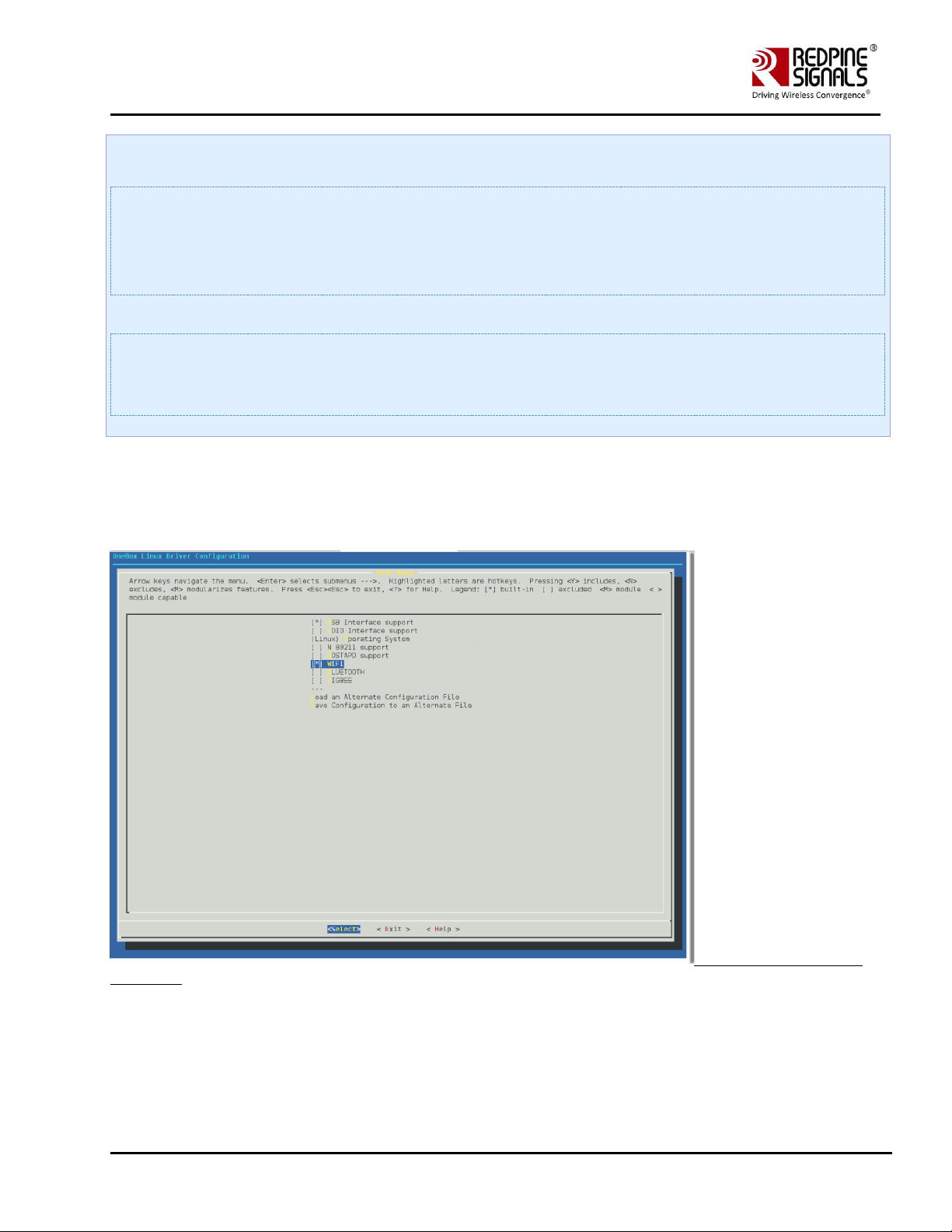
By default the configuration is enabled with Wi-Fi, Bluetooth and ZigBee. If the user wants to compile the driver for a
particular protocol, he can disable the unwanted protocols in Menuconfig utility. In case of coex mode, the Wi-Fi must
always be enabled in conjunction with BT / ZigBee protocols, even if Wi-Fi will not be used.
For example, if the user wants to compile the driver only for Bluetooth only, the Wi-Fi and Bluetooth mode must be
enabled. Refer to the following images of Menuconfig utility for more information:
Figure 4: Selection of WIFI
Only Mode
3. After selecting the configuration, exit the menuconfig and save the configuration. Please refer the given below image of
saving the configuration.
Page 16

Redpine Signals, Inc. Proprietary and Confidential Page 16
RS9116 n-Link Linux and Android
Technical Reference Manual
Version 2.0
Figure 5: Save the changes
before exiting
4. Now to compile the driver, enter the following command:
make
The code is compiled and the binaries are generated in the source/host/release folder. For embedded platforms, modify
the path assigned to the "DEF_KERNEL_DIR" variable in the Makefile:
cd RS9116.NXX.NL.GEN.LNX.x.y.z/source/host
vim Makefile
The DEF_KERNEL_DIR variable has to be assigned along with the compiled kernel path. For an x86 based Linux platform,
the path is usually "/lib/modules/<kernel_version>/build" and this is the path assigned in the Makefile provided in the
package.
Example:
DEF_KERNEL_DIR:= /lib/modules/3.4.66/build
Next, use the "make" command to start compiling the driver. For embedded platforms, add the target platform and
toolchain path as cross compilation option to the "make" command.
Page 17

Redpine Signals, Inc. Proprietary and Confidential Page 17
RS9116 n-Link Linux and Android
Technical Reference Manual
Version 2.0
For example, if the target platform is ARM and tool chain path is "/opt/freescale/usr/local/gcc-4.4.4-glibc-2.11.1multilib-1.0/arm-fsl-linux-gnueabi/bin/arm-none-linux-gnueabi-", then the command is issued as:
make ARCH=arm CROSS_COMPILE=/opt/freescale/usr/local/gcc-4.4.4-glibc-2.11.1-multilib-1.0/arm-fsl-linuxgnueabi/bin/arm-none-linux-gnueabi-
Before installing the Onebox RS9116 Driver modules, make sure that the RSI opensource modules are uninstalled.
This has been taken care in the onebox_insert.sh script.
In order to un-install the RSI opensource driver, use the following commands:
# rmmod rsi_usb
# rmmod rsi_sdo
# rmmod rsi_91x
Page 18

Redpine Signals, Inc. Proprietary and Confidential Page 18
RS9116 n-Link Linux and Android
Technical Reference Manual
Version 2.0
4 Installing the Driver
4.1 Installation of Modules
After completion of compilation, the driver generates the following modules in the release folder. They are outlined
below:
• onebox_common_gpl.ko
• onebox_gpl.ko
• onebox_nongpl.ko
• onebox_wlan_gpl.ko
• onebox_wlan_nongpl.ko
• onebox_bt_gpl.ko
• onebox_bt_nongpl.ko
• onebox_zb_gpl.ko
• onebox_zb_nongpl.ko
• wlan.ko
• wlan_wep.ko
• wlan_ccmp.ko
• wlan_tkip.ko
• wlan_acl.ko
• wlan_scan_sta.ko
• wlan_xauth.ko
Load various modules in the following order:
Load onebox common gpl module
# insmod onebox_common_gpl.ko
Load protocol related Modules (Wi-Fi, BT, ZigBee)
Load common Hal Modules (onebox_nongpl.ko and onebox_gpl.ko).
4.2 Enabling a Protocol
Execute following command to enable required protocol(s):
# ./onebox_util rpine0 enable_protocol $protocol_value
Below are the possible values of protocol.
• 1 – Enables Wi-Fi only
• 2 – Enables Bluetooth only
• 4 – Enables ZigBee only
• 3 – Enables both Wi-Fi+Bluetooth
• 5 – Enables both Wi-Fi+ZigBee
Note:
• If user selects only Wi-Fi in Menuconfig during the compilation of Driver, use the command below :
sh wlan_enable.sh
• If user selects only Bluetooth in Menuconfig during the compilation of Driver, use the command below :
sh bt_enable.sh
Page 19

Redpine Signals, Inc. Proprietary and Confidential Page 19
RS9116 n-Link Linux and Android
Technical Reference Manual
Version 2.0
• If user selects only ZigBee in Menuconfig during the compilation of Driver, use the command below:
sh zigb_enable.sh
• If user selects both Wi-Fi and Bluetooth in Menuconfig during the compilation of Driver, use the command below :
sh wlan_bt_insert.sh
• If user selects both Wi-Fi and ZigBee in Menuconfig during the compilation of Driver, use the command below :
sh wlan_zigb_insert.sh
• If user selects all the protocols in Menuconfig during the compilation of Driver, use the command below :
sh onebox_insert.sh
and need to run individual protocol enable scripts.
4.3 Disabling a Protocol
Execute he following command to disable required protocol(s):
# ./onebox_util rpine0 disable_protocol $protocol_value
• the possible values of protocol is same as mentioned in Enabling a Protocol.
Note:
• If user wants to disable only WLAN, use the command below :
sh wlan_disable.sh
• If user wants to disable only Bluetooth, use the command below :
sh bt_disable.sh
• If user wants to disable only ZigBee, use the command below :
sh zigb_disable.sh
• If user wants to disable both WLAN and Bluetooth or both WLAN and ZigBee , use the command below :
sh remove_all.sh
Disabling of protocol is not recommended when Wi-Fi is operating in AccessPoint mode.
4.4 OneBox-Mobile in Wi-Fi Only Mode
The steps for starting the Wi-Fi Only mode in Client, AccessPoint and Wi-Fi Direct modes are as follows:
1. Open the common_insert.sh file present in the "release" folder.
2. Ensure DRIVER_MODE and COEX_MODE are set as below:
• DRIVER_MODE = 1
• COEX_MODE = 1 (For Station Mode only/WIFI-Direct)
• COEX_MODE = 2 (For Access Point Mode)
• COEX_MODE = 3 (For Both Access Point and Station Modes)
For SDIO mode, ensure that the SDIO stack related modules are already inserted in the kernel refer Appendix A:
Configuration of Kernels from 3.13 and above section to install sdio stack modules .
4.4.1 Installation in Wi-Fi Client Mode (with BSD interface support)
The steps for installing OneBox-Mobile software in Wi-Fi Client Mode are as follows:
1. Edit the "sta_settings.conf" file in the "release" folder and enter the parameters of the Wi-Fi network as given below:
For Open (non-Secure) mode
network={
Page 20

Redpine Signals, Inc. Proprietary and Confidential Page 20
RS9116 n-Link Linux and Android
Technical Reference Manual
Version 2.0
ssid="<SSID of Access Point>"
key_mgmt=NONE
}
For WPA-PSK (TKIP) mode
network={
ssid="<SSID of Access Point>"
key_mgmt=WPA-PSK
psk=<passphrase specified in the Access Point>
proto=WPA
pairwise=TKIP
group=TKIP
}
For WPA2-PSK (CCMP) mode
network={
ssid="<SSID of Access Point>"
key_mgmt=WPA-PSK
psk=<passphrase specified in the Access Point>
proto=WPA2
pairwise=CCMP
group=CCMP
}
For WEP-64 mode
network={
ssid="<SSID of Access Point>"
key_mgmt=NONE
wep_key0=XXXXXXXXXX
wep_tx_keyidx=X
}
The key can be input either in ASCII or Hexadecimal formats:
ASCII Format: wep_key0="12345"
Hexadecimal Format: wep_key0=1234567890
The key index can vary between 0 and 3.
For WEP-128 mode
network={
ssid="<SSID of Access Point>"
key_mgmt=NONE
Page 21

Redpine Signals, Inc. Proprietary and Confidential Page 21
RS9116 n-Link Linux and Android
Technical Reference Manual
Version 2.0
wep_key0=XXXXXXXXXXXXXXXXXXXXXXXXXX
wep_tx_keyidx=X
}
The key can be input either in ASCII or Hexadecimal formats:
ASCII Format: wep_key0="1234567890123"
Hexadecimal Format: wep_key0=12345678901234567890123456
The key index can vary between 0 and 3.
For WEP-Shared (64-bit) mode
network={
ssid="<SSID of Access Point>"
key_mgmt=NONE
wep_key0=XXXXXXXXXX
wep_tx_keyidx=X
auth_alg=SHARED
}
The key can be input either in ASCII or Hexadecimal formats:
ASCII Format: wep_key0="12345"
Hexadecimal Format: wep_key0=1234567890
The key index can vary between 0 and 3.
To connect to an Access Point whose SSID is not broadcast (Hidden), add the following line to the network block.
scan_ssid=1
For example
network={
ssid="<SSID of Access Point>"
scan_ssid=1
key_mgmt=NONE
}
Next, run the "start_sta.sh" script in the "release" folder to load the driver modules and the supplicant and also connect
to the Access Point specified in the "sta_settings.conf" file.
sh start_sta.sh
Page 22

Redpine Signals, Inc. Proprietary and Confidential Page 22
RS9116 n-Link Linux and Android
Technical Reference Manual
Version 2.0
User needs to make sure of the module detection w.r.t interface being used. If the module is not detected, user will
end up with errors displayed on the console !
After issuing the above command, a virtual interface with the name "wifi0" will be created. You can view the list of
interfaces by entering the following command:
ifconfig –a
You can check whether the connection to the Access Point is successful or not, by running the following command:
iwconfig wifi0
The sample output of this command is
wifi0 IEEE 802.11bgn ESSID:"Range" Nickname:""
Mode:Managed Frequency:2.412 GHz Access Point: 38:A4:ED:DE:BB:06
Bit Rate:39 Mb/s Tx-Power=16 dBm Sensitivity=1/0
RTS thr:off Fragment thr:off
Encryption key:****-**** Security mode:restricted
Power Management:off
Link Quality=80/80 Signal level=-28 dBm Noise level:0 dBm
Rx invalid nwid:0 Rx invalid crypt:0 Rx invalid frag:0
Tx excessive retries:0 Invalid misc:0 Missed beacon:0
This command gives the status of the device. If the connection is successful, then the connected Access point SSID along
with the MAC address is displayed. If it is not connected to an Access point, a message "Not Associated" is displayed.
To view the list of Access Points scanned in each channel, you can run the following command in the "release" folder.
./wpa_cli –i wifi0 scan_results
To obtain an IP address using DHCP, start the DHCP client by entering below commands. (1st command to remove entry
for existing dhcp and 2nd to create a new entry).
$ dhclient -r wifi0
$ dhclient -v wifi0
The sample output of dhclient command is given below
Listening on LPF/wifi0/88:da:1a:1e:b2:58
Sending on LPF/wifi0/88:da:1a:1e:b2:58
Sending on Socket/fallback
DHCPDISCOVER on wifi0 to 255.255.255.255 port 67 interval 4 (xid=0x133cec16)
Page 23

Redpine Signals, Inc. Proprietary and Confidential Page 23
RS9116 n-Link Linux and Android
Technical Reference Manual
Version 2.0
DHCPREQUEST on wifi0 to 255.255.255.255 port 67 (xid=0x133cec16)
DHCPOFFER from 192.168.43.1
DHCPACK from 192.168.43.1 (xid=0x133cec16)
bound to 192.168.43.167 -- renewal in 1783 seconds
4.4.2 Installation in Access Point Mode (with BSD interface support)
The steps for installing OneBox-Mobile software in Access Point Mode are as follows:
1. The "start_ap.sh" script present in the "release" folder needs to be run with the different configuration files present
in the same folder in order to install an Access Point in different security modes.
# sh start_ap.sh <conf_file>
For example : sh start_ap.sh wpa_supplicant_open.conf
The different configuration files (.conf files) present in the "release" folder are as follows:
For Access Point in Open Mode, wpa_supplicant_open.conf configuration file is used, and this starts an Access Point with
the following parameters:
• SSID: REDPINE_AP
• Channel 1 of 2.4GHz Band (2412 MHz)
• Open (non-Secure) mode
For Access Point in WEP-64 Mode, wpa_supplicant_wep64.conf configuration file is used, and this starts an Access Point
with the following parameters:
• SSID: onebox_wep
• Channel 1 of 2.4GHz Band (2412 MHz)
• Security Mode: WEP-64
• WEP Key: 1234567890
• Key Index: 0
For Access Point in WEP-128 Mode, wpa_supplicant_wep128.conf configuration file is used, and this starts an Access Point
with the following parameters:
• SSID: onebox_wep
• Channel 1 of 2.4GHz Band (2412 MHz)
• Security Mode: WEP-128
• WEP Key: 12345678901234567890123456
• Key Index: 0
For Access Point in WPA-PSK (TKIP) Mode, wpa_supplicant_tkip.conf configuration file is used, and this starts an Access
Point with the following parameters:
• SSID: onebox_tkip
• Channel 1 of 2.4GHz Band (2412 MHz)
• Security Mode: WPA-PSK (TKIP)
• Passphrase: "12345678"
For Access Point in WPA2-PSK (CCMP) Mode, wpa_supplicant_ccmp.conf configuration file is used, and this starts an
Access Point with the following parameters:
• SSID: onebox_ccmp
• Channel 1 of 2.4GHz Band (2412 MHz)
• Security Mode: WPA2-PSK (CCMP)
• Passphrase: "12345678"
Page 24

Redpine Signals, Inc. Proprietary and Confidential Page 24
RS9116 n-Link Linux and Android
Technical Reference Manual
Version 2.0
All the above mentioned parameters can be modified in the respective configuration files by the user. The values
provided in the above mentioned parameters are only for reference.
The Access Point does not support WEP-Shared algorithm in the current release.
2. After running the "start_ap.sh" script a virtual interface with the name "wifi1" will be created. You can view the list of
interfaces using the following command:
ifconfig –a
You can check whether the Access Point has been started successfully or not, by running the following command:
iwconfig wifi1
The sample output of this command is
wifi1 IEEE 802.11bgn ESSID:"test" Nickname:""
Mode:Master Frequency:2.432 GHz Access Point: 88:DA:1A:16:E5:5D
Bit Rate:6 Mb/s Tx-Power=30 dBm Sensitivity=1/0
RTS thr:off Fragment thr:off
Encryption key:off
Power Management:off
Link Quality=80/80 Noise level:0 dBm
Rx invalid nwid:0 Rx invalid crypt:0 Rx invalid frag:0
Tx excessive retries:0 Invalid misc:0 Missed beacon:0
This command gives the status of the device. It displays the Access Point's SSID along with the MAC address and channel
frequency. If the Access Point does not start, a message saying "Exiting: Driver Initialization not completed even after
waiting for xxms" is displayed.
To start a DHCP server, use the commands below.
sh dhcp_server.sh wifi1
Note: If DHCP server is not present , we can also assign IP statically by using following command. Also it should be noted
that dhclient at connected clients will not work as dhcp server is not started at AP. We should assign IP statically at client
side also.
ifconfig <interface> <IP>
Example : ifconfig wifi1 192.168.2.1
4.4.3 Installation in Wi-Fi Client Mode (with NL80211 support)
The steps for installing Wi-Fi Only mode in Client are as follows:
1. Open the common_insert.sh file present in the "release" folder.
2. Ensure that the DRIVER_MODE and COEX_MODE are set as below:
Page 25

Redpine Signals, Inc. Proprietary and Confidential Page 25
RS9116 n-Link Linux and Android
Technical Reference Manual
Version 2.0
• DRIVER_MODE = 1
• COEX_MODE = 1 (For Station Mode only/WIFI-Direct)
or
• COEX_MODE = 3 (For Both Access Point and Station Modes)
For SDIO mode, ensure that the SDIO stack related modules are already inserted in the kernel refer Appendix A:
Configuration of Kernels from 3.13 and above section to install sdio stack modules .
Ensure that in menuconfig, NL80211 support is enabled as mentioned in Figure 4.
3. Compile the driver.
Make sure the following parameters are enabled in the supplicant configuration file
(wlan/supplicant/linux/wpa_supplicant/.config)
CONFIG_DRIVER_NL80211=y
CONFIG_LIBNL32=y
$ make
4. Go to the release folder and start the device in station mode.
$ cd release
$ sh wlan_enable.sh
5. Issue the following command to get physical interfaces on which we can add wifi0 interface
$iw phy | grep phy
The output of the command will be phyX (X can be 1,2,3,… eg:phy1,phy2 etc)
In case of multiple phy's to identify the appropriate phy on which to run the command, enter the following
command.
iw dev
The sample output of this command is
phy#3
Interface wlp0s26u1u2
Page 26

Redpine Signals, Inc. Proprietary and Confidential Page 26
RS9116 n-Link Linux and Android
Technical Reference Manual
Version 2.0
ifindex 10
wdev 0x300000001
addr 00:23:a7:65:2a:ac
type managed
phy#0
Interface wlo1
ifindex 3
wdev 0x1
addr a4:17:31:a7:82:a3
type managed
In the above example "Phy3" is Redpine's interface.
Assuming the physical interface is detected as phy1, refer the below steps to create a virtual interface.
6. Add the wireless interface to the phy.
$service NetworkManager stop
$iw phy phy1 interface add wifi0 type managed
Instead of following the above 2 steps i.e. step 5 and step 6, we can directly create vap by using "onebox_util" binary
present in the release folder.
cd release
./onebox_util rpine0 create_vap wifi0 sta sw_bmiss
Run the supplicant after configuring sta_settings.conf with required AP settings as mentioned in the section Installation in
Wi-Fi Client Mode (with BSD interface support)
In the sta_settings.conf file, in addition to the above all configurations as mentioned for BSD case, NL80211 mode
required country input in the global fields which need to be set as specified below.
country=US
Now run supplicant as given below.
$ ./wpa_supplicant -i wifi0 -D nl802ll -c sta_settings.conf -ddddt > log &
4.4.4 Installation in Wi-Fi AP mode (with NL80211 support)
The steps for installing Wi-Fi Only mode in AP are as follows:
1. Open the common_insert.sh file present in the "release" folder.
2. Ensure that the DRIVER_MODE and COEX_MODE are set as below
• DRIVER_MODE = 1
• COEX_MODE = 2 (For Access Point Mode)
(Or)
Page 27

Redpine Signals, Inc. Proprietary and Confidential Page 27
RS9116 n-Link Linux and Android
Technical Reference Manual
Version 2.0
• COEX_MODE = 3 (For Both Access Point and Station Modes)
3. Ensure that in menuconfig, NL80211 and HOSTAPD support is enabled.
4. Compile the driver.
Make sure the following parameters are enabled in the hostapd configuration file (wlan/hostapd-
2.4/hostapd/.config)
CONFIG_LIBNL32=y
$ make
Compilation of NL80211 requires libnl library files. Please refer to page Appendix F: Installation of Missing Generic
Netlink Libraries for configuration of hoapd.conf file for libnl and installing libnl drivers if they are not available.
5. Go to the release folder and start the device in Access Point mode.
$ cd release
$ sh wlan_enable.sh
6. Issue the following command to get physical interfaces on which we can add wifi0 interface
$iw phy | grep phy
The output of the command will be phyX (X can be 1,2,3,… eg:phy1,phy2 etc)
• Now add wifi0 interface to phyX.
• $service NetworkManager stop
• $iw phy phy1 interface add wifi0 type __ap
Instead of following the above steps in step 6, we can directly create vap by using "onebox_util" binary present in the
release folder
$ ./onebox_util rpine0 create_vap wifi0 ap
Configure the SSID Settings of the AP in the hostapd_open.conf file (say if you are starting AP in open mode).
In order to start AP in a particular band and channels, configure variables hw_mode, channel and country in
hostapd_open.conf (present in release folder) file as follows :
• hw_mode=a ('a'-5GHz and 'g'-2.4GHz)
• channel=36
• country_code=US
Note:
Channel selection in the hostapd_open.conf file should be appropriate as per the band selected.
Page 28

Redpine Signals, Inc. Proprietary and Confidential Page 28
RS9116 n-Link Linux and Android
Technical Reference Manual
Version 2.0
Make sure in hostapd_open.conf file, the AP netdevice name is set to wifi0 or wifi1 according to the interface obtained by
following the above steps.
For eg:
• Interface = wifi0
Note: Refer section Appendix G: Considerations need to be made during hostapd usage for description of other
configurable parameters of hostapd.conf file(s).
7. Run hostapd with following command
$ ./hostapd hostapd_open.conf –ddddt> log &
In the same way, we can also configure required SSID and Passphrase and key management settings in
hostapd_ccmp.conf, hostapd_wep.conf, hostapd_tkip.conf files accordingly.
If you want to use Auto Channel Selection using hostapd refer ACS with Hostapd section.
4.4.5 Installation in Wi-Fi Direct Mode (With BSD Interface Support)
The steps for installing OneBox-Mobile software in Wi-Fi Direct Mode are as follows:
The "start_p2p.sh" script present in the "release" folder needs to be run in order to start the supplicant and also for
installing the Wi-Fi Direct mode. The configurable parameters in the p2p.conf file are outlined below:
• listen channel
• operating channel
• GO Intent
After starting the supplicant, the p2p_commands mentioned below should be executed.
• To find other P2P networks
• #. /wpa_cli –i wifi0 p2p_find
• To find other P2P devices in range
• #. /wpa_cli –i wifi0 p2p_peers
• To connect to a P2P network
• #. /wpa_cli –i wifi0 p2p_connect <BSS ID> pbc go_intent=<intent value>
Here the intent value range is between 0 and 15 (Putting intent value to 0 makes p2p device as client and 15 makes p2p
device as group owner).
4.4.5.1 Autonomous GO Mode
The given below command is used to start the device in Autonomous GO mode:
# ./wpa_cli –i wifi0 p2p_group_add freq=<channel_freq>
The "channel_freq" input mentioned in the above command is the center frequency of the Wi-Fi channel in which the GO
needs to be started The OneBox-Mobile software supports DFS slave mode. However, DFS Channels need to be avoided
till the module is certified for DFS.. If this parameter is not provided, then the GO will start in the channel specified in the
p2p.conf file.
Legacy Wi-Fi clients (non P2P clients) need a passphrase to connect to the p2p group. The command given below
generates the passphrase for legacy Wi-Fi clients.
#. /wpa_cli –i wifi0 p2p_get_passphrase
Page 29

Redpine Signals, Inc. Proprietary and Confidential Page 29
RS9116 n-Link Linux and Android
Technical Reference Manual
Version 2.0
4.4.6 Installation in Wi-Fi Direct Mode (With NL80211 Support only for Kernel v3.8 or higher)
The steps for installing OneBox-Mobile software in Wi-Fi Direct Mode are as follows:
The "start_p2p_nl80211.sh" script present in the "release" folder needs to be run in order to start the supplicant and also
for installing the Wi-Fi Direct mode. The configurable parameters in the p2p_nl80211.conf file are outlined below:
• listen channel
• operating channel
• GO Intent
wpa_supplicant version used should be latest one (2.6 or higher). Please check the start_p2p_nl80211.sh script for better
understanding and update it accordingly.
After starting the supplicant, the p2p_commands mentioned below should be executed.
• To find other P2P networks
#. /wpa_cli –i wifi0 p2p_find
• To find other P2P devices in range
#. /wpa_cli –i wifi0 p2p_peers
• To connect to a P2P network
#. /wpa_cli –i wifi0 p2p_connect <BSS ID> pbc go_intent=<intent value>
Here the intent value range is between 0 and 15 (Putting intent value to 0 makes p2p device as client and 15 makes p2p
device as group owner). If you are becoming GO, dhcp server should be running on GO Interface.
4.4.6.1 Autonomous GO Mode
The steps for installing OneBox-Mobile software in Wi-Fi Direct Mode are as follows:
The "start_p2pgo.sh" script present in the "release" folder needs to be run in order to start the supplicant and also for
installing the Wi-Fi Direct mode. The configurable parameters in the p2p_nl80211.conf file are outlined below:
• listen channel
• operating channel
• GO Intent
wpa_supplicant version used should be latest one (2.6 or higher). Please check the start_p2pgo.sh script for better
understanding and update it accordingly.
The given below command is used to start the device in Autonomous GO mode:
# ./wpa_cli –i wifi0 p2p_group_add freq=<channel_freq>
The "channel_freq" input mentioned in the above command is the center frequency of the Wi-Fi channel in which the GO
needs to be started The OneBox-Mobile software supports DFS slave mode. However, DFS Channels need to be avoided
till the module is certified for DFS.. If this parameter is not provided, then the GO will start in the channel specified in the
p2p_nl80211.conf file.
Page 30

Redpine Signals, Inc. Proprietary and Confidential Page 30
RS9116 n-Link Linux and Android
Technical Reference Manual
Version 2.0
• P2P Devices can scan this Group Owner and can connect directly. Run following command to start receiving connect
calls from P2P devices
#. /wpa_cli –i wifi0
- > wps_pbc
You will start getting ENROLEE detect calls from other P2P Devices in the vicinity. You can see the running logs on wpa_cli
prompt for the device getting connected.
• Legacy Wi-Fi clients (non P2P clients) need a passphrase to connect to the p2p group. The command given below
generates the passphrase for legacy Wi-Fi clients.
#. /wpa_cli –i wifi0 p2p_get_passphrase
• Run DHCP Server on GO Interface before connecting P2P or Legacy devices.
4.5 OneBox-Mobile in Wi-Fi + Bluetooth Classic Coexistence Mode
This section explains about the installation of Wi-Fi and BT Classic modes. Please note that in case of using Coexistence
mode, each protocol should be loaded individually one after the other.
• Open the common_insert.sh file present in the "release" folder.
• Ensure that the DRIVER_MODE and COEX_MODE are set as below:
- DRIVER_MODE = 1
- COEX_MODE = 5(For WLAN Station and BT Classic Mode)
- COEX_MODE = 6 (For WLAN Access Point and BT Classic Mode)
For SDIO mode, ensure that the SDIO stack related modules are already inserted in the kernel refer Appendix A:
Configuration of Kernels from 3.13 and above section to install sdio stack modules .
1. Follow the instructions mentioned in the section 4.4.1 Installation in Wi-Fi Client Mode inorder to install the Wi-Fi
Client mode.
2. Run the "bt_enable.sh" or wlan_bt_insert.sh or onebox_insert.sh script present in the "release" folder as per the
instructions given in the Installing the Driver in order to start the Bluetooth Classic mode. This script inserts Bluetooth
modules and common HAL modules, provided if it is not already inserted.
3. You can check whether the BT Classic mode has been started successfully or not, by running the following command:
hciconfig
If the driver is loaded correctly, the above command displays a network adaptor named "hciX". An example output is
given below:
hci0:Type: BR/EDR Bus: SDIO
BD Address: 00:23:A7:00:05:68 ACL MTU: 1021:8 SCO MTU: 30:8
UP RUNNING PSCAN
RX bytes:478 acl:0 sco:0 events:20 errors:0
TX bytes:331 acl:0 sco:0 commands:19 errors:0
4. After the device is up, we can pair it with the other devices using the Bluetooth Manager application. The files can also
be sent and received using Bluetooth Manager. Instead of Bluetooth Manager, the device can be configured using
"hcitool" or "hciconfig". The procedure for using Bluetooth Manager is explained in the section Appendix C: Using the
Bluetooth Manager
Page 31

Redpine Signals, Inc. Proprietary and Confidential Page 31
RS9116 n-Link Linux and Android
Technical Reference Manual
Version 2.0
4.6 OneBox-Mobile in Wi-Fi + Bluetooth LE Coexistence Mode
This section describes the installation of Wi-Fi and Bluetooth LE (BLE) modes. Please note that in case of using Coexistence
mode, each protocol should be loaded individually one after the other.
• Open the common_insert.sh file present in "release" folder.
• Ensure that the DRIVER_MODE and COEX_MODE as set as below
- DRIVER_MODE = 1
- COEX_MODE = 9 (For WLAN Station and BT LE)
Note:
For SDIO mode, ensure that the SDIO stack related modules are already inserted in the kernel refer Appendix A:
Configuration of Kernels from 3.13 and above section to install sdio stack modules .
1. Follow the instructions in section 4.4.1 Installation in Wi-Fi Client Mode, inorder to install the Wi-Fi Client mode.
2. Run the bt_enable.sh or wlan_bt_insert.sh or onebox_insert.sh script present in the "release" folder as per the
instructions present in the section 4.1 inorder to start the Bluetooth LE mode. This script inserts Bluetooth modules as
well as common HAL modules, provided if it is not inserted initially.
3. You can check whether the BLE mode has been started successfully or not, by running the following command:
# hciconfig
If the driver is loaded correctly, the above command displays a network adaptor named "hciX". An example output is given
below:
hci0:Type: BR/EDR Bus: SDIO
BD Address: 00:23:A7:00:05:68 ACL MTU: 1021:8 SCO MTU: 30:8
UP RUNNING PSCAN
RX bytes:478 acl:0 sco:0 events:20 errors:0
TX bytes:331 acl:0 sco:0 commands:19 errors:0
4. After the device is up, we can Advertise, Scan and Connect with other BLE devices. The device can be configured using
hcitool or hciconfig.
4.6.1 Advertise, Scan, Connect Commands
The commands for Advertise, Scan and Connect are as follows:
• Enable Advertise
# hciconfig –a <hciX> leadv
• Disable Advertise
# hciconfig –a <hciX> noleadv
• Initiate Scan
Page 32

Redpine Signals, Inc. Proprietary and Confidential Page 32
RS9116 n-Link Linux and Android
Technical Reference Manual
Version 2.0
# hcitool -i <hciX> lescan
The above command displays the scan responses and advertising information.
• Master Mode Connected State
Ensure that the remote device is in Advertise mode and then issue the command given below:
# hcitool –i <hciX> lecc <remote_MAC_Addr>
The "remote_MAC_Addr" parameter mentioned above is the MAC address of the remote device, e.g., 00:23:AC:01:02:03.
• Slave Mode Connected State
Ensure that our device is in Advertise mode and then issue the command given below:
# hcitool –i <hciX> lecc <device_MAC_Addr>
The "device_MAC_Addr" parameter mentioned above is the MAC address of the Redpine module, e.g., 00:23:AC:01:02:03.
4.7 OneBox-Mobile in Wi-Fi + Bluetooth Classic + Bluetooth LE Coexistence Mode
This section explains about the installation of Wi-Fi +Bluetooth Classic and Bluetooth LE modes.
Please note that in case of using Coexistence mode, each protocol should be loaded individually one after the other.
• Open the common_insert.sh file present in the "release" folder.
• Ensure that the DRIVER_MODE and COEX_MODE are set as below:
- DRIVER_MODE = 1
- COEX_MODE = 14(For WLAN Access Point, BT Classic and BT LE)
- COEX_MODE = 13(For WLAN Station, BT Classic and BT LE)
1. Follow the instructions mentioned in the section Installation in Access Point Mode (with BSD interface support), in
order to install the Wi-Fi Access Point mode.
2. Run the bt_enable.sh or wlan_bt_insert.sh or onebox_insert.sh script present in the "release" folder as per the
instructions mentioned in Installation of Modules to start the Bluetooth LE mode. This script inserts Wi-Fi, Bluetooth
modules as well as common HAL modules, provided if it is not inserted initially.
3. To check whether the Bluetooth Classic and Bluetooth LE mode has been started successfully or not, run the given
below command.
# hciconfig
If the driver has been installed successfully, the above mentioned command displays a network adapter named "hciX". An
example output is given below:
hci0:Type: BR/EDR Bus: SDIO
BD Address: 00:23:A7:xx:xx:xx ACL MTU: 1021:8 SCO MTU: 30:8
UP RUNNING PSCAN
RX bytes:478 acl:0 sco:0 events:20 errors:0
TX bytes:331 acl:0 sco:0 commands:19 errors:0
Page 33

Redpine Signals, Inc. Proprietary and Confidential Page 33
RS9116 n-Link Linux and Android
Technical Reference Manual
Version 2.0
4. After the device is up, we can Advertise, Inquiry, Scan and Connect with other BT Classic and BLE devices. The device
can be configured using hcitool or hciconfig applications.
5. After the device is up, we can pair it with the other devices or from other devices using the Bluetooth Manager
application. The files can also be sent and received using Bluetooth Manager. Instead of Bluetooth Manager, the device
can be configured using "hcitool" or "hciconfig". The procedure for using Bluetooth Manager is explained in the section
Appendix C: Using the Bluetooth Manager.
NOTE: To know the device type for BT i.e., device is supporting LE or BR/EDR
By giving command: hciconfig -a hcix features
Example1:For LE Opermode i.e., DRIVER_MODE = 1 & COEX_MODE = 8
Command:hciconfig -a hci1 features
hci1: Type: Primary Bus: USB
BD Address: 88:DA:1A:16:E4:4F ACL MTU: 251:10 SCO MTU: 0:0
Features page 0: 0xbf 0xfe 0x0d 0xbe 0xfb 0xff 0x41 0x85
<3-slot packets> <5-slot packets> <encryption> <slot offset>
<timing accuracy> <role switch> <sniff mode> <RSSI>
<channel quality> <SCO link> <HV2 packets> <HV3 packets>
<u-law log> <A-law log> <CVSD> <power control>
<transparent SCO> <EDR ACL 2 Mbps> <EDR ACL 3 Mbps>
<enhanced iscan> <interlaced iscan> <interlaced pscan>
<extended SCO> <EV4 packets> <EV5 packets> <AFH cap. slave>
<AFH class. slave> <BR/EDR not supp.> <LE support>
<3-slot EDR ACL> <5-slot EDR ACL> <sniff subrating>
<pause encryption> <AFH cap. master> <AFH class. master>
<EDR eSCO 2 Mbps> <EDR eSCO 3 Mbps> <3-slot EDR eSCO>
<extended inquiry> <non-flush flag> <LSTO> <EPC>
<extended features>
Features page 1: 0x00 0x00 0x00 0x00 0x00 0x00 0x00 0x00
Example2:For Classic(BT BR/EDR) Only i.e DRIVER_MODE = 1 & COEX_MODE = 4
Command:hciconfig -a hci1 features
hci1: Type: Primary Bus: USB
BD Address: 88:DA:1A:16:E4:4F ACL MTU: 1021:3 SCO MTU: 64:3
Features page 0: 0xbf 0xfe 0x0d 0xfe 0x9b 0xff 0x59 0x87
<3-slot packets> <5-slot packets> <encryption> <slot offset>
<timing accuracy> <role switch> <sniff mode> <RSSI>
<channel quality> <SCO link> <HV2 packets> <HV3 packets>
<u-law log> <A-law log> <CVSD> <power control>
<transparent SCO> <EDR ACL 2 Mbps> <EDR ACL 3 Mbps>
<enhanced iscan> <interlaced iscan> <interlaced pscan>
<inquiry with RSSI> <extended SCO> <EV4 packets> <EV5 packets>
<AFH cap. slave> <AFH class. slave> <3-slot EDR ACL>
<5-slot EDR ACL> <sniff subrating> <pause encryption>
<AFH cap. master> <AFH class. master> <EDR eSCO 2 Mbps>
<EDR eSCO 3 Mbps> <3-slot EDR eSCO> <extended inquiry>
<simple pairing> <encapsulated PDU> <non-flush flag> <LSTO>
<inquiry TX power> <EPC> <extended features>
Features page 1: 0x01 0x00 0x00 0x00 0x00 0x00 0x00 0x00
Example3:For the Classic and LE i.e DRIVER_MODE = 1 & COEX_MODE = 12
Command:hciconfig -a hci1 features
Page 34

Redpine Signals, Inc. Proprietary and Confidential Page 34
RS9116 n-Link Linux and Android
Technical Reference Manual
Version 2.0
hci1: Type: Primary Bus: USB
BD Address: 88:DA:1A:16:E4:4F ACL MTU: 1021:3 SCO MTU: 64:3
Features page 0: 0xbf 0xfe 0x0d 0xfe 0xdb 0xff 0x5b 0x87
<3-slot packets> <5-slot packets> <encryption> <slot offset>
<timing accuracy> <role switch> <sniff mode> <RSSI>
<channel quality> <SCO link> <HV2 packets> <HV3 packets>
<u-law log> <A-law log> <CVSD> <power control>
<transparent SCO> <EDR ACL 2 Mbps> <EDR ACL 3 Mbps>
<enhanced iscan> <interlaced iscan> <interlaced pscan>
<inquiry with RSSI> <extended SCO> <EV4 packets> <EV5 packets>
<AFH cap. slave> <AFH class. slave> <LE support>
<3-slot EDR ACL> <5-slot EDR ACL> <sniff subrating>
<pause encryption> <AFH cap. master> <AFH class. master>
<EDR eSCO 2 Mbps> <EDR eSCO 3 Mbps> <3-slot EDR eSCO>
<extended inquiry> <LE and BR/EDR> <simple pairing>
<encapsulated PDU> <non-flush flag> <LSTO> <inquiry TX power>
<EPC> <extended features>
Features page 1: 0x03 0x00 0x00 0x00 0x00 0x00 0x00 0x00
Features page 2: 0x30 0x00 0x00 0x00 0x00 0x00 0x00 0x00
4.8 OneBox-Mobile in Wi-Fi + ZigBee Coexistence Mode
This section explains about the installation of Wi-Fi and ZigBee (ZB) modes. Please note that in case of using Coexistence
mode, each protocol should be loaded individually one after the other.
1. Open the common_insert.sh file present in "release" by using an editor like gvim.
2. Ensure that the DRIVER_MODE and COEX_MODE are set as given below
• DRIVER_MODE = 1
• COEX_MODE = 17 ( For Wlan Station and ZigBee)
For SDIO mode, ensure that the SDIO stack related modules are already inserted in the kernel refer Appendix A:
Configuration of Kernels from 3.13 and above section to install sdio stack modules .
3. Follow the instructions mentioned in the section Installation in Wi-Fi Client Mode, inorder to install the Wi-Fi Client
mode.
4. Run the "zigb_insert.sh" script present in the "release" folder inorder to start the ZigBee mode. This script inserts
ZigBee modules and common HAL modules, provided if it is not inserted initially.
5. You can check whether the ZigBee mode has been started successfully or not, by running the given below command:
# ifconfig –a
If the driver is loaded correctly, the above command displays a network adapter named "zigb0".
4.8.1 Building and Running the Sample Home Automation Switch Application
To help in evaluating the ZigBee mode, a sample Home Automation switch application is made available with the release.
You will need a 3rd party ZigBee Coordinator and ZigBee-enabled Light bulb which support the Home Automation Profile.
Ensure that the Coordinator and Light bulb are switched on and are in connected state before proceeding further.
Page 35

Redpine Signals, Inc. Proprietary and Confidential Page 35
RS9116 n-Link Linux and Android
Technical Reference Manual
Version 2.0
4.8.1.1 About the Sample Application
This is the ZigBee Home Automation-defined switch application using Host APIs. This application connects to the light
parent and tries to match the simple descriptors by using Match Descriptor command.
After exchanging the simple descriptors, it will send the toggle command to the light continuously.
4.8.1.2 Host API Folder Structure
The folder structure for host API along with sample applications has been given below. This folder structure is available in
the "ZigBee/utils" folder.
The folders in the ZigBee/utils folder are as follows:
• apis – contains the core APIs and sample application
- core – contains the host mode API implementation.
- ref_apps – contains the reference HA switch application.
- build - contains Makefile to compile core and ref_apps irrespective of reference project.
• reference_projects – contains code related to netlink sockets which is used to communicate with driver.
4.8.1.3 Building and Running the Home Automation Sample Application
The steps for building and running the home automation sample application are as follows:
1. Go to the folder "ZigBee/utils/reference_projects/src"
2. Clean the existing builds by entering the given below command
# make clean
3. Build the Home Automation Switch application by using the given below command
# make switch
4. Run the switch app by entering the given below command
# ./rsi_wsc_zigb_app
4.9 Driver Uninstallation Procedure
The driver can be uninstalled along with the different modules by using the scripts provided in the "release" folder.
1. remove_all.sh: Uninstall the complete driver and all the modules including the common HAL modules .
# sh remove_all.sh
4.10 Driver Information
4.10.1 Driver Statistics
Use the given below command inorder to view Wi-Fi driver statistics:
cat /proc/rpine<$id>/stats
Page 36

Redpine Signals, Inc. Proprietary and Confidential Page 36
RS9116 n-Link Linux and Android
Technical Reference Manual
Version 2.0
<$id> Indicates Id of Wi-Fi device. For example if rpine0 is created for module then to view Wi-Fi related statistics related
to module then Use the below command:
# cat /proc/rpine0/stats
When 2nd usb device is connected to same host then rpine1 will get created, In order to see the Wi-Fi related statistics
related to 2nd usb module use the below command:
cat /proc/rpine1/stats
This command prints statistics related to the total management packets, total data packets with respect to a given access
category sent to/from the driver, buffer full status as well as semi buffer full status, FSM states etc.
4.10.2 Disabling Driver Debug Prints
You may opt to disable the debug prints of the driver appearing on the console by using the given below command.
Ensure that the driver is installed correctly before using this command for SDIO interface.
# echo 0x0 > /proc/onebox-hal/debug_zone
For USB interface, the proc name is onebox-mobile$devnum$busnum.
# echo 0x0 > /proc/onebox-hal<$devnum$busnum>/debug_zone
Page 37

Redpine Signals, Inc. Proprietary and Confidential Page 37
RS9116 n-Link Linux and Android
Technical Reference Manual
Version 2.0
5 Wi-Fi ioctl Usage Guide
This section explains about the usage of various ioctl commands present in the OneBox-Mobile driver. The user has
control over multiple settings such as device settings, radio, aggregation, fragmentation thresholds, power save
configurations and so on.
5.1 Configuring using Wireless Extensions
iwconfig" is a generic Linux based wireless tool which is used for setting parameters for a wireless network interface. It
may be used in lieu of the Wi-Fi supplicant provided as a part of the OneBox-Mobile software. However, care has to be
taken to follow the correct sequence of commands while using "iwconfig". The Redpine Signals recommends usage of the
supplicant provided in the software package.
This section describes the usage of "iwconfig" in conjunction with the Onebox-Mobile driver. For a detailed description of
the tool, refer to the relevant main pages in Linux.
"iwconfig" only works when the driver is operating in the 'BSD' mode.
The details of the Access Point for which the n-Link® is connected in the Client mode can be viewed by using the given
below command.
# iwconfig <vap_name>
The table below describes the usage of the command in more detail.
Set Channel/Frequency (only in Monitor mode)
Description
This command is used to set the Channel for the n-Link® module.
Default value
1
Input
Parameters
VAP Name (string like wifi0, wifi1, etc.)
Channel number
Output
Parameter
None
Reset
required
No
Usage
# iwconfig <vap_name> freq <channel_no>
(OR)
# iwconfig <vap_name> channel <channel_no>
Example
# iwconfig wifi0 freq 6
(OR)
# iwconfig wifi0 channel 6
Set Data Transmit Rate
Description
This command is used to set the data rate for transmission.
Default value
0 (Auto Rate)
Input
Parameters
VAP Name (string like wifi0, wifi1, etc.)
Integer value as per the mapping below:
Auto Rate – 0
1 Mbps – 2
2 Mbps – 4
5.5 Mbps – 11
11 Mbps – 22
Page 38

Redpine Signals, Inc. Proprietary and Confidential Page 38
RS9116 n-Link Linux and Android
Technical Reference Manual
Version 2.0
Set Channel/Frequency (only in Monitor mode)
6 Mbps – 12
12 Mbps – 24
18 Mbps – 36
24 Mbps – 48
36 Mbps – 72
48 Mbps – 96
54 Mbps – 108
MCS0 – 13
MCS1 – 26
MCS2 – 39
MCS3 – 52
MCS4 – 78
MCS5 – 104
MCS6 – 117
MCS7 – 130
Output
Parameter
None
Reset
required
No
Usage
# iwconfig <vap_name> rate <rate_val>
Note: For Access Point mode, this command has to be issued after the Set Mode command only if the VAP
has started using “iwconfig” commands and not using the supplicant provided by Redpine Signals. For
Client mode, the Set Mode command is not mandatory
Set RTS/CTS Threshold (only in Access Point mode)
Description
This command is used to set the RTS/CTS threshold of the n-Link® Module.
Default Value
2346
Input
Parameters
VAP Name (string like wifi0, wifi1, etc.)
Integer between 256 and 2346
Output
Parameter
None
Reset
Required
No.
Usage
# iwconfig <vap_name> rts <payload_size>
Example
The command below sets the RTS/CTS threshold to 1008 bytes:
# iwconfig wifi0 rts 1008
Set Transmit Power
Description
This command is used to set the transmit power of the n-Link® Module
Note: If the value of transmit power set in the above command exceeds the maximum allowable power
supported by
the channel specified by the regulatory domain, then the minimum of the two values shall be used
Default Value
-
Input
Parameters
VAP Name (string like wifi0, wifi1, etc.)
Integer value in dBm
Output
Parameter
None
Reset
No
Page 39

Redpine Signals, Inc. Proprietary and Confidential Page 39
RS9116 n-Link Linux and Android
Technical Reference Manual
Version 2.0
Set Channel/Frequency (only in Monitor mode)
Required
Usage
# iwconfig <vap_name> txpower <val_in_dBm>
Example
# iwconfig wifi0 txpower 10
Note:
Txpower setting can be defined as the minimum value that can be picked from the max regulatory power
settings, from any user defined value and also from the maximum values the radio can support.
So it is not guaranteed that the user defined value gets effected when these settings is done.
Table 1: iwconfig Usage
5.2 Private (Driver-Specific) Commands for Access Point and Client Modes
The "iwpriv" command is used to set parameters specific to the OneBox-Mobile software. The table below lists the usage
of the "iwpriv" command for setting and getting parameters common for the Access Point and Client modes.
Set Short GI
Description
This command is used to set the Short GI mode of the n-Link® Module.
Default Value
0 (Short GI disabled for both 20 MHz and 40 Mhz Bandwidth)
Input
Parameters
VAP Name (string like wifi0, wifi1, etc.)
The integer value mapping has been shown below:
0 –Disable Short GI
1 –Enable Short GI for 20MHz Bandwidth
2 –Enable Short GI for 40MHz Bandwidth
3 –Enable Short GI for 20MHz and 40MHz Bandwidths
Output
Parameter
None
Reset Required
Yes. Refer to the example for the reset process
Usage
# iwpriv <vap_name> short_gi <value>
Example
The commands given below set the Short GI for 20MHz bandwidth and then reset the adapter for the
command to take effect:
# iwpriv wifi0 short_gi 1
# ./onebox_util rpine0 reset_adapter
Note:
Issue this ioctl before starting the supplicant.
Get Short GI
Description
This command is used to get the value programmed for Short GI mode of the n-Link® Module
Default Value
-
Input
Parameters
VAP Name (string like wifi0, wifi1, etc.)
Output
Parameter
The integer value mapping has been shown below:
0 – Disable Short GI
32 – Enable Short GI for 20MHz Bandwidth
64 – Enable Short GI for 40MHz Bandwidth
96 – Enable Short GI for 20MHz and 40MHz Bandwidths
Reset Required
No
Usage
# iwpriv <vap_name> get_short_gi
Example
The command given below explains about getting the Short GI programmed in the module:
Page 40

Redpine Signals, Inc. Proprietary and Confidential Page 40
RS9116 n-Link Linux and Android
Technical Reference Manual
Version 2.0
Set Short GI
# iwpriv wifi0 get_short_gi
Get Privacy
Description
This command is used to get the Privacy bit of the n-Link® Module
Default Value
-
Input
Parameters
VAP Name (string like wifi0, wifi1, etc.)
Output
Parameter
The integer value mapping has been shown below:
0 – Privacy is disabled
1 – Privacy is enabled
Reset Required
No
Usage
# iwpriv <vap_name> get_privacy
Example
The command given below tells about like how to get the Privacy information in the module:
# iwpriv wifi0 get_privacy
Set WMM (only in Access Point mode)
Description
This command is used to enable the WMM (QoS) feature of the n-Link® Module
Default Value
1 (Enabled)
Input
Parameters
VAP Name (string like wifi0, wifi1, etc.)
The integer value mapping has been shown below:
0 – Disable
1 – Enable
Output
Parameter
None
Reset Required
No
Usage
# iwpriv <vap_name> wmm <value>
Example
The command below sets the WMM mode for the module:
# iwpriv wifi0 wmm 1
Note: Issue this command before starting the supplicant in Access Point Mode.
Set AMPDU
Description
This command is used to enable AMPDU Aggregation in the n-Link® Module
Default Value
-
Input
Parameters
VAP Name (string like wifi0, wifi1, etc.)
The integer value mapping has been shown below:
0 – Disable AMPDU Aggregation
1 – Enable AMPDU Aggregation for Transmit, disable for Receive
2 – Enable AMPDU Aggregation for Receive, disable for Transmit
Output
Parameter
None
Reset Required
No
Usage
# iwpriv <vap_name> ampdu_set <value>
Example
The command given below disables A-MPDU aggregation:
# iwpriv wifi0 ampdu_set 0
The command given below enables A-MPDU aggregation for Transmit:
# iwpriv wifi0 ampdu_set 1
Set Bandwidth
Page 41

Redpine Signals, Inc. Proprietary and Confidential Page 41
RS9116 n-Link Linux and Android
Technical Reference Manual
Version 2.0
Set Short GI
Description
This command is used to enable or disable 20/40 MHz Bandwidths in the n-Link® Module.
Default Value
-
Input
Parameters
VAP Name (string like wifi0, wifi1, etc.)
The integer value mapping has been shown below:
1- Enable only 20MHz
2- Enable only 40MHz
3 – Enable both 20 and 40MHz
Output
Parameter
None
Reset Required
Yes. Refer to the example for the reset process for Client and Access Point modes
Usage
# iwpriv <vap_name> set_htconf <value>
Example
The commands given below is used to delete and create the VAP to set the bandwidth in Access Point
mode:
# ./onebox_util rpine0 delete_vap wifi0
# ./onebox_util rpine0 create_vap wifi0 ap
# iwpriv wifi0 set_htconf $value
# ./wpa_supplicant –i wifi0 wpa_supplicant_open.conf &
Note:
Issue this ioctl before starting the supplicant.
The commands given below is used to set the 20MHz bandwidth in Client mode and reset the Client for
the command to take effect:
# iwpriv wifi0 set_htconf 1
# ./onebox_util rpine0 reset_adapter.
Set Debug Zone
Description
This command is used to select the debug zone for Wifi.
Default Value
0x4000
Input
Parameters
Zone value.
The integer value mapping has been shown below:
0 – Disable zone.
0x4000 – Error Zone.
Output
Parameter
None
Reset Required
No
Usage
# iwpriv <vap name> set_dbg_zone <zone_value>
Example
The following command disables debug zone level.
# iwpriv wifi0 set_dbg_zone 0
Table 2: iwpriv Usage for Access Point and Client Modes
5.3 Private (Driver- Specific) Commands for Access Point Mode
The table below describes the usage of the "iwpriv" command for setting and getting parameters common for the Access
Point Mode.
Set DTIM Period
Description
This command is used to set the DTIM period in the n-Link® Module. Issue this command before
starting the supplicant.
Page 42

Redpine Signals, Inc. Proprietary and Confidential Page 42
RS9116 n-Link Linux and Android
Technical Reference Manual
Version 2.0
Set DTIM Period
Default Value
1
Input Parameters
VAP Name (string like wifi0, wifi1, etc.)
Integer value between 1 and 15
Output Parameter
None
Reset Required
Yes. In order to set the DTIM period, the virtual interface has to be reset.
Usage
1. iwpriv <vap_name> dtim_period <value>
Example
The commands given below is used to reset the VAP and set the DTIM period:
#sh remove_all.sh
#sh wlan_enable.sh (or) wlan_bt_insert.sh (or) wlan_zigb_insert.sh (or) onebox_insert.sh
script present in the "release" folder as per the instructions in Section 4.1
#./onebox_util rpine0 create_vap wifi1 ap
#iwpriv wifi1 dtim_period $value
#./wpa_supplicant –I wifi1 –D bsd –c wpa_supplicant_open.conf –ddddt > log &
Note:
Issue this ioctl before starting the supplicant in Access Point.
Get DTIM Period
Description
This command is used to get the DTIM period in the n-Link® Module.
Default Value
-
Input Parameters
VAP Name (string like wifi0, wifi1, etc.)
Output Parameter
Integer value renges between 1 and 15
Reset Required
No.
Usage
iwpriv <vap_name> get_dtim_period
Example
The command given below is used to get the DTIM period programmed in the module:
#iwpriv wifi0 get_dtim_period
Get Beacon Interval
Description
This command is used to get the Beacon Interval programmed in the n-Link® Module
Default Value
-
Input Parameters
VAP Name (string like wifi0, wifi1, etc.)
Output Parameter
Integer value
Reset Required
No
Usage
# iwpriv <vap_name> get_bintval
Example
The command given below is used to get the Beacon interval programmed in the module:
#iwpriv wifi0 get_bintval
MAC Command
Description
This command is used to set the Access Policy based on MAC address. The Access Policy can be
disabled or can be used to allow or deny traffic from the MAC address.[1]
Note:
All the acl policy commands need to be issued before starting the wpa_supplicant.
Default Value
-
Input Parameters
VAP Name (string like wifi0, wifi1, etc.)
The integer value mapping has been shown below:
0 – Disable Access Policy
1 – Enable Access Policy and Allow traffic
2 – Enable Access Policy and Deny traffic
Page 43

Redpine Signals, Inc. Proprietary and Confidential Page 43
RS9116 n-Link Linux and Android
Technical Reference Manual
Version 2.0
Set DTIM Period
Output Parameter
None
Reset Required
No
Usage
# iwpriv <vap_name> maccmd <value>
Example
The command given below enables the ACL Policy and allows traffic:
# iwpriv wifi0 maccmd 1
The command given below enables the ACL Policy and denies traffic:
# iwpriv wifi0 maccmd 2
Add MAC Address for
Access Policy
Description
This command is used to add a MAC address for the Access Policy in the n-Link® Module.
Default Value
-
Input Parameters
VAP Name (string like wifi0, wifi1, etc.)
48-bit MAC Address in hexadecimal format with colon separation. e.g., 00:23:A7:01:02:03
Output Parameter
None
Reset Required
No
Usage
# iwpriv <vap_name> addmac <mac_addr>
Example
The command given below adds a MAC Address (10:10:A9:12:13:14) to the ACL Policy:
# iwpriv wifi0 addmac 10:10:a9:12:13:14
Note: Issue this command before a Station connects to the module.
Delete MAC Address
from Access Policy list
Description
This command is used to delete a MAC address from the Access Policy described in the n-Link®
Module
Default Value
-
Input Parameters
VAP Name (string like wifi0, wifi1, etc.)
48-bit MAC Address in hexadecimal format with colon separation.
e.g., 00:23:A7:01:02:03
Output Parameter
None
Reset Required
No
Usage
# iwpriv <vap_name> delmac <mac_addr>
Example
The command given below is used to delete a MAC Address (10:10:A9:12:13:14) from the ACL
Policy:
# iwpriv wifi0 delmac 10:10:a9:12:13:14
Set Hidden SSID
Description
This command is used to stop broadcasting of the SSID of the Access Point in the n-Link®
Module’s beacons and probe responses.
Default Value
0 (Hidden SSID Disabled)
Input Parameters
VAP Name (string like wifi0, wifi1, etc.)
The integer value mapping has been shown below:
0 – Disable Hidden SSID (SSID is broadcast)
1 – Enable Hidden SSID (SSID is not broadcast)
Output Parameter
None
Reset Required
Yes. In order to move from/to Hidden SSID mode, the virtual interface has to be reset.
Page 44

Redpine Signals, Inc. Proprietary and Confidential Page 44
RS9116 n-Link Linux and Android
Technical Reference Manual
Version 2.0
Set DTIM Period
Usage
# iwpriv <vap_name> hide_ssid <value>
Example
The command given below is used to start the Access Point in hidden mode:
# ./onebox_util rpine0 create_vap wifi0 ap
# iwpriv wifi0 hide_ssid 1
# ./wpa_supplicant –i wifi0 –D bsd –c wpa.conf &
Note:
Issue this ioctl before starting the supplicant.
Set DFS channel to
switch to
Description
This command is used to select a channel to switch to in case of Radar Detection in Access Point
mode. This is used only when the bsd driver is used.
Default Value
Disabled (A channel gets picked at random)
Input Parameters
VAP Name (string like wifi0, wifi1, etc.)
Frequency of the channel to switch to in case of radar detection.
Output Parameter
None
Reset Required
No
Usage
# iwpriv <vap name> dfs_chan_switch <frequency>
Example
The following command sets the channel 36 as the channel for switching to.
# iwpriv wifi0 dfs_chan_switch 5180
Set Mgmt Rate
Description
This command is used to set the mgmt rate
Default Value
0
Input Parameters
value*2
Output Parameter
None
Reset Required
No
Usage
# iwpriv <vap name> mgmt_rate <value*2>
Example
The Following command sets the mgmt rate to 5.5Mbps
#iwpriv wifi0 mgmt_rate 11
To disable the mgmt_rate use the below command:
#iwpriv wifi0 mgmt_rate 0
Set Keep Alive Period in
AP mode
Description
This command is used to set the Keep Alive period in the n-Link® Module. It is recommended
that this command is given after the VAP is created and before wpa_supplicant/hostapd is
started
Default Value
240 seconds
Input Parameters
VAP Name (string like wifi0, wifi1, etc.)
Integer value ranges between 15 and 12000 (seconds).
Integer value should be a multiple of 15, if the value is not a multiple of 15, it will rounded off to
nearst multiple of 15.
Output Parameter
None
Reset Required
No
Usage
# iwpriv <vap_name> keep_alive <value>
Example
The command given below sets the Keep Alive period to 30 seconds, after rounding off 35 to the
Page 45

Redpine Signals, Inc. Proprietary and Confidential Page 45
RS9116 n-Link Linux and Android
Technical Reference Manual
Version 2.0
Set DTIM Period
nearest multiple of 15.
# iwpriv wifi0 keep_alive 35
Table 3: iwpriv Usage for Access Point Mode
5.4 Private (Driver- Specific) Commands for Client Mode
The table below lists the usage of the "iwpriv" command for setting and getting parameters common for the Client Mode.
De authenticate while
Roaming
Description
This command is used to de authenticate the n-Link® Module from "old" Access Point while
roaming.
Default Value
NULL Data
Input Parameters
VAP Name (string like wifi0, wifi1, etc.)
Integer value - 0 or 1
0 – Inform Access Point that the module is going to be in power save mode.
1 – De authenticate from the previous Access Point during Roaming.
Output Parameter
None
Reset Required
No
Usage
iwpriv <vap_name> setparam 12 The value 12 is used for setting Roaming related
parameters
for the setparam command. <value>
Example
The command below sends de authentication during roaming.
iwpriv wifi0 setparam 12 1
Set Keep Alive Period
Description
This command is used to set the Keep Alive period in the n-Link® Module.
Default Value
90 seconds
Input Parameters
VAP Name (string like wifi0, wifi1, etc.)
Integer value ranges between 15 and 12000 (seconds)
Output Parameter
None
Reset Required
No
Usage
# iwpriv <vap_name> keep_alive <value>
Example
The command given below sets the Keep Alive period to 100 seconds:
# iwpriv wifi0 keep_alive 100
Table 4: iwpriv Usage for Client Mode
5.5 Configuring Using onebox_util
The "onebox_util" program is provided to configure the n-Link® module for parameters which are not specific to a virtual
interface (VAP). The table below describes the usage of the "onebox_util" command for setting and getting the
parameters.
Create a VAP The
OneBox-Mobile
software allows
creation of 4 VAPs
Description
This command is used to create a virtual interface (VAP) in the operating mode specified.
Note: The OneBox-Mobile software allows creation of 4 VAPs
Default Value
-
Page 46

Redpine Signals, Inc. Proprietary and Confidential Page 46
RS9116 n-Link Linux and Android
Technical Reference Manual
Version 2.0
Create a VAP The
OneBox-Mobile
software allows
creation of 4 VAPs
Input Parameters
Base Interface (string like rpine0)
VAP Name (string like wifi0, wifi1, etc.)
Operating Mode (string):
ap – Access Point Mode
sta – Station/Client Mode
p2p – P2P Mode
mon – Monitor Mode Refer to the section Monitor Mode for more details.
Beacon Filtering after connecting to an Access Point (only for Client mode). Valid inputs are:
sw_bmiss – Beacon filtering disabled. All beacons of connected Access Point provided to Host driver.
hw_bmiss – Beacon filtering is enabled. The Beacon is provided to Host driver when there is a
change in the Beacon from the connected Access Point.
This feature also programs the device to indicate to the Host driver when 20 consecutive beacons
are not received by the device.
Output Parameter
None
Reset Required
No
Usage
./onebox_util <base_interface> create_vap <vap_name> <op_mode>
Example
The command given below creates a virtual interface named wifi0 in the Client mode with Beacon
filtering disabled.
/onebox_util rpine0 create_vap wifi0 sta sw_bm
Delete a VAP
Description
This command is used to delete an existing virtual interface (VAP).
Default Value
-
Input Parameters
Base Interface (string like rpine0)
VAP Name (string like wifi0, wifi1, etc.)
Output Parameter
None
Reset Required
No
Usage
# ./onebox_util <base_interface> delete_vap <vap_name>
Example
The command given below deletes a virtual interface named wifi0.
# ./onebox_util rpine0 delete_vap wifi0
Print VAP Statistics
Description
This command is used to print the statistics of the transmitted and received packets of an existing
virtual interface (VAP).
Default Value
-
Input Parameters
VAP Name (string like wifi0, wifi1, etc.)
[-v] – Get description of the fields in the statistics
Filename (string) to which the statistics will be written
Output Parameter
Statistics like:
1) Number of Beacons transmitted (for Access Point/P2P GO modes)
2) Number of Beacons received (for Client/P2P Client modes)
3) Number of Management packets received
4) Number of packets received from a different BSS
etc.
Page 47

Redpine Signals, Inc. Proprietary and Confidential Page 47
RS9116 n-Link Linux and Android
Technical Reference Manual
Version 2.0
Create a VAP The
OneBox-Mobile
software allows
creation of 4 VAPs
Reset Required
No
Usage
# ./onebox_util <vap_name> print_vap_stats [-v] [-f filename]
Example
The command given below prints the statistics of the transmitted and received packets of the
interface wifi0 into the file “stats”.
# ./onebox_util wifi0 print_vap_stats -v -f stats
Print Station
Statistics (only in
Access Point mode)
Description
This command is used to print the statistics of the packets exchanged between the Access Point and
a Station.
Default Value
-
Input Parameters
VAP Name (string like wifi0, wifi1, etc.)
48-bit MAC Address in hexadecimal format with colon separation. e.g., 00:23:A7:01:02:03
[-v] – Get description of the fields in the statistics
Filename (string) to which the statistics will be written
Output Parameter
Statistics like:
1) Number of Beacons received
2) Number of Management packets transmitted/received
3) Number of Unicast/Multicast packets transmitted/received
4) Number of data packets transmitted/received
5) Number of Probe Request/Response packets transmitted/received etc.
Usage
# ./onebox_util <vap_name> print_station_stats <mac_addr> [-v] [-f filename]
Example
The command below logs the statistics of the packets exchanged between the Access Point (wifi0)
and a Station with MAC address 00:1C:2b:10:19:1a into the file named “stats”.
#./onebox_util wifi0 print_station_stats 00:1C:2b:10:19:1a -v -f stats
Select Antenna
Description
This command is used to select one of the two RF ports connecting to antennas. For the modules
without integrated antenna, it is used to select between pins RF_OUT_1 and RF_OUT_2. For the
modules with integrated antenna and U.FL connector, it is used to select between the two. In case
Antenna Diversity feature is enabled, this ioctl will not have any effect. The Antenna selection will
happen automatically at the firmware level.
Note:
This ioctl is redundant. Refer to Section 16 for futher details. The functionality of the ioclt is intact.
However it might be removed in the future to reduce redundancy.
Default Value
2
Input Parameters
Base Interface (string like rpine0)
The integer value mapping has been shown below:
2 – Select RF_OUT_2/Integrated Antenna
3 – Select RF_OUT_1/U.FL Connector
Output Parameter
None
Reset Required
No
Usage
# ./onebox_util <base_interface> ant_sel <value>
Example
The command given below selects the U.FL connector in case of modules with integrated antenna
Page 48

Redpine Signals, Inc. Proprietary and Confidential Page 48
RS9116 n-Link Linux and Android
Technical Reference Manual
Version 2.0
Create a VAP The
OneBox-Mobile
software allows
creation of 4 VAPs
and will select RF_OUT_1 pin in the case of the module without an integrated antenna.
# ./onebox_util rpine0 ant_sel 3
Enable Background
Scan and Set
Parameters (only in
Client mode)
Description
This command is used to enable background scan and set the relevant parameters. Refer to the
section on Background Scan Parameters for more details on each parameter.
Default Value
2
Input Parameters
Base Interface (string like rpine0)
Background Scan Threshold
RSSI Tolerance Threshold
Periodicity
Active Scan Duration
Passive Scan Duration
Two Probe Enable
Number of Background Scan Channels
Channels to Scan
Note: The OneBox-Mobile software supports DFS slave mode. However, DFS Channels need to be
avoided till the module is certified for DFS.
Output Parameter
None
Reset Required
No.
Usage
# ./onebox_util <base_interface> set_bgscan_params <bgscan_threshold>
<rssi_tolerance_threshold> <periodicity> <active_scan_duration> <passive_scan_duration>
<two_probe_enable> <num_of_bgscan_channels> <channels_to_scan>
Example
The command given below enables Background Scan with a scan threshold of 10, RSSI tolerance
threshold of 10, periodicity of 3 seconds, active scan duration of 20 milliseconds, passive scan
duration of 100 milliseconds, two-probe enabled and the channels 36, 40 and 44.
# ./onebox_util rpine0 set_bgscan_params 10 10 3 20 100 1 3 36 40 44
Note
In order to select 11J channels 8, 12, 16, enter the channel number as 8J, 12J, 16J respectively.
Remaining 11J channels can be selected with their channel numbers.
Example:
# ./onebox_util rpine0 set_bgscan_params 10 10 3 20 100 1 4 36 40 44 8J
Host-Triggered
Background Scan
(only in Client mode)
Description
This command is used to trigger background scan without waiting for the periodicity mentioned in
bgscan_parameters.
Default Value
-
Input Parameters
-
Output Parameter
None
Reset Required
No.
Usage
# ./onebox_util <base_interface> do_bgscan
Page 49

Redpine Signals, Inc. Proprietary and Confidential Page 49
RS9116 n-Link Linux and Android
Technical Reference Manual
Version 2.0
Create a VAP The
OneBox-Mobile
software allows
creation of 4 VAPs
Example
The command given below triggers background scan without waiting for periodicity timeout.
# ./onebox_util rpine0 do_bgscan
Note: The do_bgscan command has to be followed by set_bgscan_params command.
Set SSID for
Background Scan
(only in Client mode)
Description
This command is used to set the SSID of the Hidden Access Point (SSID not being broadcast) during
Background Scan.
Default Value
-
Input Parameters
Base Interface (string like rpine0)
SSID (max. 32 characters)
Output Parameter
None
Reset Required
No.
Usage
# ./onebox_util <base_interface> bgscan_ssid <ssid>
Example
The command below sets the SSID of a Hidden Access Point during Background Scan.
# ./onebox_util rpine0 bgscan_ssid REDPINE_AP
Note: The bgscan_ssid command has to be followed by the set_bgscan_params or do_bgscan
command in
order for the Probe Request to be sent with the SSID requested in the bgscan_ssid command.
Enable Power Save
and Set Parameters
(only in Client mode)
Description
This command is used to enable/disable power save modes and set the required power save mode
for the n-Link® module. Refer to the section Power save Modes, Profiles and Parameters for more
details on each parameter and their usage.
Default Value
-
Input Parameters
Base Interface (string like rpine0)
Power Save Enable/Disable
Sleep Type
Transmit Threshold
Receive Threshold
Transmit Hysteresis
Receive Hysteresis
Monitor Interval
Sleep Duration
Listen Interval Duration
Number of Beacons per Listen Interval
DTIM Interval Duration
Number of DTIMs Per Sleep Duration
Output Parameter
None
Reset Required
No.
Usage
# ./onebox_util <base_interface> set_ps_params <ps_en> <sleep_type> <tx_threshold>
<rx_threshold> <tx_hysteresis> <rx_hysteresis> <monitor_interval> <sleep_duration>
Page 50

Redpine Signals, Inc. Proprietary and Confidential Page 50
RS9116 n-Link Linux and Android
Technical Reference Manual
Version 2.0
Create a VAP The
OneBox-Mobile
software allows
creation of 4 VAPs
<listen_interval_duration> <num_beacons_per_listen_interval> <dtim_interval_duration>
<num_dtims_per_sleep>
Example
The command below enables ULP Power Save Mode for a duration of 100 ms and with a
listen_interval_duration of 100ms.
# ./onebox_util rpine0 set_ps_params 1 2 0 0 0 0 0 100 100 0 0 1
Enable UAPSD
(Normal and Mimic
modes) and Set
Parameters
Description
This command is used to enable the UAPSD mode and set the relevant parameters. If the Access
Point does not support UAPSD, the module tries to mimic this mode. Refer to the section Power
save Modes, Profiles and Parameters for more details.[1]
Default Value
-
Input Parameters
Base Interface (string like rpine0)
UAPSD Wakeup Period in milliseconds – 0 for Transmit Based UAPSD and between 10 and 100 for
Periodic UAPSD.
UAPSD Service Period Length- This field indicates number of packets delivered by AP to station after
receiving one trigger frame. This filed value ranges between 0-3 as described below.
0-All buffered packets will be delivered.
1-Two buffered packets will be delivered.
2-four buffered packets will be delivered.
3-six buffered packets will be delivered.
Output Parameter
None
Reset Required
No.
Usage
# ./onebox_util <base_interface> set_uapsd_params 0xF <sp_len> <uapsd_wakeup_period>
Example
The command enables UAPSD mode and sets the wakeup period as 100ms.
# ./onebox_util rpine0 set_uapsd_params 0xF 0 100
Note: The set_uapsd_params command needs to be followed by the command given below for the
values to take effect.
# ./onebox_util <base_interface> reset_adapter
Reset Adapter (only
in Client mode)
Description
This command is used to reset the Client mode virtual interface. This command can be used to
change certain configurations of the Client mode and reset the VAP for the configurations to take
effect.
Default Value
-
Input Parameters
Base Interface (string like rpine0) – the base interface input ensures that the Client mode VAP is
reset irrespective of the actual VAP name.
Output Parameter
-
Reset Required
-
Usage
/onebox_util <base_interface> reset_adapter
Example
/onebox_util rpine0 reset_adapter
Page 51

Redpine Signals, Inc. Proprietary and Confidential Page 51
RS9116 n-Link Linux and Android
Technical Reference Manual
Version 2.0
Create a VAP The
OneBox-Mobile
software allows
creation of 4 VAPs
Set Beacon Interval
(only in Access Point
mode)
Description
This command is used to set the Beacon Interval in milliseconds. It is recommended that this
command is given before the VAP is created.
Default Value
200
Input Parameters
Base Interface (string like rpine0)
Integer value between 50 and 1000 (other values will result in default value being assigned).
Output Parameter
None
Reset Required
Yes. In order to set the beacon interval, the virtual interface has to be reset.
Usage
# ./onebox_util <base_interface> set_beacon_intvl <beacon_intvl>
Example
The commands given below are used to reset the Access Point and set the beacon interval to 100ms.
# sh remove_all.sh
# sh wlan_enable.sh or wlan_bt_insert.sh or wlan_zigb_insert.sh or onebox_insert.sh script present
in the “release” folder as per the instructions in Installation of Modules
# ./onebox_util rpine0 set_beacon_intvl 100
# ./onebox_util rpine0 create_vap wifi0 ap
# ./wpa_supplicant –i wifi0 -D bsd –c wpa.conf -ddddt &
Note:
Issue this command before creating any virtual Access Point interfaces.
Set WMM
Parameters (only in
Access Point mode)
Description
This command is used to set the WMM parameters for specific queues.
Note: This ioctl is redundant, refer to the Section 16 for further details. The functionality of the ioclt
is intact, however it might be removed in the future inorder to reduce redundancy.
Default Value
Access Point:
AIFSN
Cwmin
Cwmax
TxOp
AC_BE
3 4 6 0 AC_BG
7 4 10 0 AC_VI
1 3 4
94
AC_VO
1 2 3
47
Station:
AIFSN
Cwmin
Cwmax
TxOp
AC_BE
3 4 6 0 AC_BG
7 4 10 0 AC_VI
4 3 4
94
AC_VO
4 2 3
47
Input Parameters
VAP Name (string like wifi0, wifi1, etc.)
WMM Parameter Name (string like aifs, cwmin, cwmax, txop, acm)
Integer value. The allowed values are as follows:
Page 52

Redpine Signals, Inc. Proprietary and Confidential Page 52
RS9116 n-Link Linux and Android
Technical Reference Manual
Version 2.0
Create a VAP The
OneBox-Mobile
software allows
creation of 4 VAPs
AIFSN – 1 to 15
Cwmin – 2n-1, where ‘n’ is between 1 and 4 for BE_Q and BK_Q and between 1 and 3 for VI_Q and
VO_Q.
Cwmax – 2n-1, where ‘n’ is between 1 and 6 for BE_Q, between 1 and 10 for BK_Q and between 1
and 4 for VI_Q and VO_Q.
TxOp – 0 for BE_Q, BK_Q, 94 for VI_Q and 47 for VO_Q
Access Category (string, as mapped below):
1) VO_Q – Voice data packets queue
2) VI_Q – Video data packets queue
3) BK_Q – Background data packets queue
4) BE_Q – Best effort data packets queue
Self or Broadcast selection (Self is for the module’s Access Point VAP, Broadcast is for Clients
connected to the Access Point)
Update Params (integer value mapped as below):
0 – To set more WMM Parameters
1 – To update current WMM Parameters
Output Parameter
None
Reset Required
No. Usage
# ./onebox_util <vap_name> setwmmparams <wmm_param_name> <value> <access_category>
<self/broadcast> <update_params>
Example
The command given below updates the AIFSN value for BE Access category for connected Clients.
# ./onebox_util wifi0 setwmmparams aifsn 2 BE_Q broadcast 1
Set Country
Description
This command is used to set the country for the n-Link® Module.
Default Value
-
Input Parameters
Integer (country code) mapped as below:
REGION
COUNTRY_CODE
COUNTRY_NAME
FCC
840
UNITED STATES
124
CANADA
484
MEXICO
ETSI
250
FRANCE
56
BELGIUM
276
GERMANY
380
ITALY
JAPAN
392
JAPAN
WORLD
36
AUSTRALIA
356
INDIA
364
IRAN
458
MALAYSIA
554
NEWZEALAND
Page 53

Redpine Signals, Inc. Proprietary and Confidential Page 53
RS9116 n-Link Linux and Android
Technical Reference Manual
Version 2.0
Create a VAP The
OneBox-Mobile
software allows
creation of 4 VAPs
643
RUSSIA
702
SINGAPORE
710
SOUTH AFRICA
Output Parameter
None
Reset Required
Yes. In order to change the country code, the virtual interface has to be reset.
Usage
# ./onebox_util <base_interface> set_country <country_code>
Example
The commands below reset the VAP and set the country to Singapore in Station mode.
# sh remove_all.sh
# sh wlan_enable.sh or wlan_bt_insert.sh or wlan_zigb_insert.sh or onebox_insert.sh script present
in the “release” folder as per the instructions in Section 4.1
# ./onebox_util rpine0 set_country 702
# ./onebox_util rpine0 create_vap wifi0 sta sw_bmiss
Note:
Issue this command before creating any interfaces.
Set External Antenna
Gain
Description
This command is used to program the gain of the external antenna for the module without antenna.
The gain values are used by the module to attenuate the output transmit power so that regulatory
requirements like FCC, ETSI, etc., are not violated. This command needs to be given before creating
the VAP in the normal mode and before the “./transmit” command in the Wi-Fi Performance Test
mode. In the Wi-Fi Performance Test mode, the transmission has to be stopped each time before
the antenna gain values are programmed.
Default Value
0
Input Parameters
Base Interface (string like rpine0)
Integer value for Antenna gain for 2.4 GHz band in dBm
Integer value for Antenna gain for 5 GHz band in dBm
Output Parameters
None
Reset Required
No
Usage
# ./onebox_util <base_interface> set_ext_ant_gain <gain_2g> <gain_5g>
Example
The commands below set the Antenna gain values for 2.4 GHz and 5 GHz bands to 3 dBm and 5
dBm, respectively.
# sh remove_all.sh
# sh wlan_enable.sh or wlan_bt_insert.sh or wlan_zigb_insert.sh or onebox_insert.sh script present
in the “release” folder as per the instructions mentioned in the section Installation of Modules.
# ./onebox_util rpine0 set_ext_ant_gain 3 5
# ./onebox_util rpine0 create_vap wifi0 sta
Set Antenna Type
Description
This command is used to configure the antenna, based on its type and its mounted path. The
configuration values are used by the module to attenuate the output transmit power based on the
selected antenna type for the corresponding path so that the regulatory requirements like FCC, ETSI,
etc., are not violated. This command needs to be given before creating the VAP in the normal mode
and before the "./transmit" command in the "Wi-Fi Performance Test ioctl usage" as mentioned in
the section Wi-Fi Performance Test ioctl usage.
Page 54

Redpine Signals, Inc. Proprietary and Confidential Page 54
RS9116 n-Link Linux and Android
Technical Reference Manual
Version 2.0
Create a VAP The
OneBox-Mobile
software allows
creation of 4 VAPs
Default Value
ant_path: 1
ant_type: 1
For ant_path
• If value is 1, then it is considered as RF_OUT_2/Integrated Antenna
• If value is 2, then it is considered as RF_OUT_1/U.FL Connector.
For ant_type
• If value is 1, then it is considered as Type 1 antenna.
• If value is 2, then it is considered as Type 2 antenna.
If value is 3, then it is considered as Type 3 antenna.
Input Parameters
Use the following table to configure antenna type based on 2G and 5G gain values
2G Gain range
5G Gain range
Antenna Type
0 < Gain <= 0.99
0 < Gain <= 4.42
Type 1
0.99 < Gain <= 1.8
4.42< Gain <= 4.6
Type 2
1.8 < Gain <= 3
4.6 < Gain <= 4.9
Type 3
Output Parameters
None
Reset Required
No
Usage
./onebox_util rpine0 ant_type ant_path ant_type
Example
# ./onebox_util rpine0 ant_type 1 2
Set Wake-OnWireless LAN
Parameters (only in
Client Mode)
Description
This command is used to set the Wake-On-Wireless LAN (WoWLAN) parameters in the device. The
Host has to give this command each time when it enters and exits sleep state. Refer to the section
Wake-On-Wireless LAN Parameters for more details. GPIO_2 is used as a Host Wakeup Interrupt for
this purpose.
Default Value
-
Input Parameters
Base Interface (string like rpine0)
48-bit Source MAC Address in hexadecimal format with colon separation. e.g., 00:23:A7:01:02:03
(valid when Unicast packet filtering from specific MAC address is enabled)
Host Sleep Status
WoWLAN Flags
Output Parameters
None
Reset Required
No
Usage
# ./onebox_util <base_interface> wowlan <src_mac_addr> <host_sleep_status> <wowlan_flags>
Example
# ./onebox_util rpine0 wowlan 00:23:a7:0c:bb:aa 1 3
Set RF Power Mode
Description
This command is used to program the RF power mode to High, Medium and Low profiles. It has to
be issued before creating the VAP. The performance of the RF is best in the High power mode.
Default Value
0 - High
Page 55

Redpine Signals, Inc. Proprietary and Confidential Page 55
RS9116 n-Link Linux and Android
Technical Reference Manual
Version 2.0
Create a VAP The
OneBox-Mobile
software allows
creation of 4 VAPs
Input Parameters
The integer value mapping has been shown below:
0 – High power mode
1 – Medium power mode
2 – Low power mode
Output Parameters
None
Reset Required
No
Usage
# ./onebox_util <base_interface> set_rf_tx_rx_pwr_mode tx_value rx_value
Example
./onebox_util rpine0 set_rf_tx_rx_pwr_mode 0 1
Set scan type
Description
This command is used to select the band in which the user wants to perform the scan. Using this
command the user can either test in 2.4Ghz or 5Ghz bands.
Default Value
Both 2.4Ghz and 5Ghz bands are enabled by default.
List of possible values
1 – To scan 2.4Ghz only band
2 – To scan 5Ghz only band
Input Prameters
Integer value
Output Parameters
None
Reset Required
No
Usage
# ./onebox_util <base_interface> set_scan_type value
Example
./onebox_util rpine0 set_scan_type 1
The above command performs scan only in 2.4Ghz band.
Note:
Issue this command before creating station virtual interface.
Set Beacon Filter
(Only in AP mode)
Description
This command is used to enable beacon filtering in the firmware. All the third party beacons will be
filtered at the firmware after applying beacon filter Ioctl.
Default Value
0-Disabled by default
Input Parameters
The integer value mapping has been shown below:
0-Disabled beacon filtering
1-Enabled beacon filtering
Output Parameter
None
Reset Required
No
Usage
# ./onebox_util <base_interface> set_rx_filter 0 0 0 0 <value> 0 0
Example
./onebox_util rpine0 set_rx_filter 0 0 0 0 1 0 0
The above command does not allow beacons to be received from firmware to driver in AP mode.
Note:
In the above command BIT (0, 1, 2, 3, 5, 6) are reserved for future use. Only BIT (4) is used for
beacon filtering.
Get Tx-Power
Description
This command is used to get current value of transmit power from firmware and updates it in
Page 56

Redpine Signals, Inc. Proprietary and Confidential Page 56
RS9116 n-Link Linux and Android
Technical Reference Manual
Version 2.0
Create a VAP The
OneBox-Mobile
software allows
creation of 4 VAPs
iwconfig command.
Default Value
-
Input Parameters
-
Output Parameter
None
Reset Required
No
Usage
# ./onebox_util <base_interface> get_txpwr
Example
./onebox_util rpine0 get_txpwr
Useonly rates
Description
This command is used set the supported rates in AP mode. This will be helpfull to control the
transmit data rates of the clients connected.
Default Value
All rates supported as per regulatory domain.
Input Prameters
Integer value as per the mapping below:
1 Mbps – 2
2 Mbps – 4
5.5 Mbps – 11
11 Mbps – 22
6 Mbps – 12
12 Mbps – 24
Output Parameters
None
Reset Required
No
Usage
# ./onebox_util <base_interface> useonly_rates <rate_val> <rate_val> <rate_val>
Example
./onebox_util rpine0 useonly_rates 2 11 12
Table 5: Usage of onebox util
5.5.1 WPS Configuration
Wi-Fi Protected Setup (WPS) is a standard for easy and secure wireless network setup and connections. The OneboxMobile supports the following configuration methods:
• Push Button Method
• PIN Method – Enter and Generate
A WPS Configuration file is used for setting up a connection with a remote Access Point or Station. A sample WPS
configuration file is given below for reference.
ctrl_interface=/var/run/wpa_supplicant
update_config=1
uuid=12345678-9abc-def0-1234-56789abcdef0
device_name=RSI_P2P_DEVICE
manufacturer=Redpine Signals, Inc.
model_name=M2MCombo
model_number=9113
serial_number=03
device_type=1-0050F204-1
os_version=01020300
config_methods=display push_button keypad
Page 57

Redpine Signals, Inc. Proprietary and Confidential Page 57
RS9116 n-Link Linux and Android
Technical Reference Manual
Version 2.0
The sections below list down the steps for configuring WPS and setting up a connection in Access Point and Client modes
using the methods listed above.
5.5.1.1 Access Point Mode
The steps for configuring WPS in Access Point Mode are as follows:
1. Start the driver in Access Point mode.
2. Start the supplicant by entering the following command.
#. /wpa_supplicant –i <vap_name> -D bsd –c <wps_conf_file> -ddddt
3. For Push Button method:
• Push the button on the STA
• Enter the command below for the n-Link® Access Point
• # ./wpa_cli –i <vap_name> wps_pbc <sta_mac_addr>
This is the 3rd party Station's MAC address. If all the MAC addresses need to be allowed, the input parameter is the
string "any".
4. Wait for the STA to parse all the WPS Access Points.
5. For Enter PIN method
• Click on "Generate PIN" on the STA. A 4/8-digit numeric WPS PIN is generated.
• Enter the command below for the n-Link® Access Point
#. /wpa_cli –i <vap_name> wps_pin <sta_mac_addr> <wps_pin>
• Wait for the STA to parse all the WPS Access Points.
6. For Generate PIN method
• Enter the command below for the n-Link® Access Point
#. /wpa_cli –i <vap_name> wps_pin <sta_mac_addr>
This will generate a 4/8-digit numeric WPS PIN.
7. Enter the PIN on the STA.
8. Wait for the STA to parse all the WPS Access Points.
Note:
1. WPS_PIN and passphrase are different.
2. WPS connection timeout is 120 seconds
3. 3rd party Stations usually try to connect to all scanned WPS Access Points until they succeed in connecting to one of
them.
4. WPS can be used along with any of the Secure modes (except WEP) and also with Open mode.
Page 58

Redpine Signals, Inc. Proprietary and Confidential Page 58
RS9116 n-Link Linux and Android
Technical Reference Manual
Version 2.0
5.5.1.2 Client Mode
The steps for configuring WPS in Client mode are as follows:
1. Start the driver in Client mode.
2. Start the supplicant by entering the following command.
# ./wpa_supplicant –i <vap_name> -D bsd –c <wps_conf_file> -ddddt
3. For Push Button method:
• Push the button on the Access Point
• Enter the command below for the n-Link® STA
# ./wpa_cli –i <vap_name> wps_pbc <bssid>
Note:
This is the Access Point's MAC address. If the BSSID is not known, the input parameter will be the string named "any".
• Wait for the STA to parse all the WPS Access Points.
4. For Enter PIN method,
• Click on "Generate PIN" on the Access Point. A 4/8-digit numeric WPS PIN is generated.
• Enter the command below for the n-Link® STA
# ./wpa_cli –i <vap_name> wps_pin <bssid> <wps_pin>
1. Wait for the STA to parse all the WPS Access Points.
5. For Generate PIN method,
• Enter the command below for the n-Link® STA
#. /wpa_cli –i <vap_name> wps_pin <bssid>
• This will generate an 8-digit numeric WPS PIN.
• Enter the PIN on the Access Point
• Wait for the STA to parse all the WPS Access Points.
Page 59

Redpine Signals, Inc. Proprietary and Confidential Page 59
RS9116 n-Link Linux and Android
Technical Reference Manual
Version 2.0
6 Configuration Using CFG80211
This section explains about the usage of various IOCTL commands, which can be issued to the Onebox-Mobile™ driver
operating in CFG80211 mode from the user space.
6.1 Using iw Wireless Tool
'iw' is a new nl80211 based CLI configuration utility for wireless devices. It is used to set/get various parameters of a
wireless network interface. This section covers the usage of 'iw' when used with the Onebox-Mobile ™ driver. For a
detailed description of 'iw' tool, please refer to the relevant man pages on Linux system. The list of supported commands
via "iw" tool are listed below.
Creating a virtual Interface
Description
This command is used to create a virtual interface in the specific mode requested by user
Default Value
-
Input Parameters
<phy name > – Phy name can be obtained by using the following command
$ iw phy
In case of multiple wireless interfaces are present, please refer to the NOTE given below on how to
determine the phy name.
<interface name> – name of the virtual interface to be created
<operating mode> – operating mode of the virtual interface that can be either 'managed' for station
mode or '__ap' for access point mode.
Output Parameter
-
Reset Required
No
Usage
iw phy <phy name> interface add <interface name> type <operating mode>
Example
To create a virtual interface in Access Point mode, use the command given below:
$ iw phy phy0 interface add wifi0 type __ap
To create a virtual interface in Station mode use the command below:
$ iw phy phy0 interface add wifi0 type managed
Scan
Description
This command is used to scan for the Access points nearby our device.
Default Value
-
Input Parameters
Interface name on which scan has to be performed
Output Parameter
List of AP's scanned
Reset Required
No
Usage
The following command initiates a scan and displays the list of AP's scanned.
$ iw dev $interface_name scan
Example
$ iw dev wifi0 scan
Connect
Description
This command is used to connect devices to the Access points in open or WEP security mode.
Default Value
-
Input Parameters
SSID, BSSID, key_index, key of AP.
Output Parameter
None
Reset Required
No
Usage
Open mode:
$ iw dev $interface_name connect $SSID_NAME $BSSID.
WEP Security:
Page 60

Redpine Signals, Inc. Proprietary and Confidential Page 60
RS9116 n-Link Linux and Android
Technical Reference Manual
Version 2.0
Creating a virtual Interface
$ iw dev $interface_name $ssid_name $bssid keyid:$key_index:$key
Example
$ iw dev wifi0 connect REDPINE_AP 00:23:a7:00:05:55
The above command connects to REDPINE_AP access point in open mode
$ iw dev wifi0 REDPINE_AP 00:23:a7:00:05:55 keys d:1:234567890
The above command instructs our device to connect to the REDPINE_AP in wep64 mode with the key
index 1 and key '234567890'.
Disconnect
Description
This command is used to disconnect our device from the connected network.
Default Value
-
Input Parameters
Interface name
Output Parameter
-
Reset Required
No
Usage
iw dev $interface_name disconnect
Example
$ iw dev wifi0 disconnect
The above command disconnects our device from the connected Access point.
Link Status
Description
This command is used to get the connection status of our device.
Default Value
-
Input Parameters
Interface name.
Output Parameter
Connection status.
Reset Required
No
Usage
iw dev $interface_name link
Example
iw dev wifi0 link
Interface Info
Description
This command is used to get information about the device .
Default Value
-
Input Parameters
Interface name.
Output Parameter
Interface mac address, type, operating mode etc.
Reset Required
No
Usage
iw dev $interface_name info
Example
iw dev wifi0 info
Station Dump
Description
This command is used to station statistic information such as the amount of tx/rx bytes, the last TX
bitrate (including MCS rate)
Default Value
-
Input Parameters
Interface name.
Output Parameter
Connected Stations/AP mac address,tx bytes, rx bytes, signal level etc,. will be displayed.
Reset Required
No
Usage
iw dev $interface_name station dump
Example
iw dev wifi0 station dump
Set Power save
mode
Page 61

Redpine Signals, Inc. Proprietary and Confidential Page 61
RS9116 n-Link Linux and Android
Technical Reference Manual
Version 2.0
Creating a virtual Interface
Description
This command is used to set power save mode on/off in station mode.
Default Value
-
Input Parameters
Interface name.
Output Parameter
No
Reset Required
No
Usage
iw dev $interface_name set power_save <on | off>
Example
iw dev wifi0 set power_save <on | off>
Get Power save
mode
Description
This command is used to get power save mode on/off in station mode.
Default Value
-
Input Parameters
Interface name.
Output Parameter
Shows whether power save mode is on | off in station mode
Reset Required
No
Usage
iw dev $interface_name get power_save
Example
iw dev wifi0 get power_save
Note:
If there are multiple phys, i.e there are several instances of cfg80211 being used by different modules, then to determine
the correct phy, run the following commands:
$ cat /sys/class/ieee80211/
This will give a list of all the phy’s that are currently active.
$ cat /sys/class/ieee80211/phyX/macaddress
where 'X' is the number of the phys which are obtained from the previous command. The redpine module MAC address
(xx:xx:xx:xx:xx:xx) has to be used in the field 'macaddress'.
Generic iw commands listed below are also supported. Please refer to the man page of the utility for further information
on their usage.
$ iw phy <phyname> info
$ iw dev <devname> del
$ iw reg get
$ iw reg set <ISO/IEC 3166-1 alpha2>
$ iw dev <devname> scan dump [-u]
$ iw phy <phyname> set name <new name>
The commands that are supported only in the Access Point mode are as follows:
$ iw dev <devname> set channel <channel> [HT20|HT40+|HT40-]
$ iw dev <devname> set freq <freq> [HT20|HT40+|HT40-]
$ iw dev <devname> station del <MAC address>
$ iw dev <devname> station get <MAC address>
Limitation:
• In STA alone mode, after connection iw reg set command is not expected. If this command is given then whatever
country code is given in command will be applicable. In this case it may possible that STA may disconnect from
connected AP. e.g. STA is connected to AP in JP (Japan region) on channel 14. If user is giving command iw reg set US
then channels will be limited to 1-11 and STA will disconnect from AP and will be looking for AP in those channels only
by running scan.
Page 62

Redpine Signals, Inc. Proprietary and Confidential Page 62
RS9116 n-Link Linux and Android
Technical Reference Manual
Version 2.0
7 Enterprise security using CFG80211
7.1 Installation and configuration of FREERADIUS Server
The following packages are required to install the freeradius server 3.09:
• libtalloc-devel
• openssl-devel
The steps for downloading as well as installing the freeradius tar ball are as follows:
$ tar zxvf freeradius-server-3.0.9.tar.gz
$ cd freeradius_3.09
$ ./configure
$ make
$ make install
Configure the freeradius server as per the given steps below:
Edit users file, which will contain the “identity” and “password”.
$ vim /usr/local/etc/raddb/users
• Add the following line at the starting in the users file
test Cleartext-Password := "password"
2. As an example, “user1” is an identity and “test123” is the password that has to be entered at client side i.e. in the
sta_settings.conf file.
3. Now we need to edit “eap” file which contains the paths consisting of certificates and information about the EAPMethods supported
$ vim /usr/local/etc/raddb/mods-enabled/eap
If Free-radius version is below 3.x “eap”, it will be located in raddb folder and will be named as “eap.conf”.
In tls-config tls-common section, changes are made to point to our certificates which are placed in /etc/certs folder
tls-config tls-common {
#private_key_password = whatever
private_key_password = Wi-Fi
#private_key_file = ${certdir}/server.pem
Page 63

Redpine Signals, Inc. Proprietary and Confidential Page 63
RS9116 n-Link Linux and Android
Technical Reference Manual
Version 2.0
private_key_file = /etc/certs/wifiuser.pem
#certificate_file = ${certdir}/server.pem
certificate_file = /etc/certs/wifiuser.pem
#ca_file = ${cadir}/ca.pem
ca_file = /etc/certs/wifiuser.pem
#dh_file = ${certdir}/dh
dh_file = /etc/certs/dh
}
To start the Radius server, run the flowing command in the terminal:
$ radiusd -X
For openssl versions of range 1.0.2 release - 1.0.2h release (or) in range 1.0.1 - 1.0.1t release (or) in
range 1.1.0 - 1.1.0a release
edit radiusd.conf file
$vim /usr/local/etc/raddb/radiusd.conf
and change 'allow_vulnerable_openssl' to yes or CVE-2016-6304
allow_vulnerable_openssl =yes
(or)
allow_vulnerable_openssl ='CVE-2016-6304'
(here CVE-2016-6304 is openssl vulnerability ID which radius server will allow)
7.2 Configuration of AP and RADIUS server to use EAP methods
Hostapd is used as the RADIUS Server. The AP and the server are co-located (in the same system).
The following packages which have to be installed are as follows:
• libnl-devel
• libsqlite3x-devel
• openssl-devel
Page 64

Redpine Signals, Inc. Proprietary and Confidential Page 64
RS9116 n-Link Linux and Android
Technical Reference Manual
Version 2.0
7.2.1 Configuration of the AP
Go to driver source folder and compile it with the following options enabled:
[*] NL80211 support
[*] HOSTAPD support
$ make
To start the device in AP mode, go to the release folder and run the following commands:
$ cd release
$ sh wlan_enable.sh or wlan_bt_insert.sh or wlan_zigb_insert.sh or onebox_insert.sh
script present in the “release” folder as per the instructions mentioned in Section
4.1.
$ iw phy phyX interface add wifi1 type __ap
where 'X' represents phy number.
It can be obtained by the following command:
$ iw list | grep phy
Before starting the device in AP mode, ensure that in hostapd_eap.conf the following entities are enabled:
ieee8021x=1
own_ip_addr=192.168.2.1 /* IP address of AP */
/* RADIUS authentication server */
auth_server_addr=127.0.0.1
auth_server_port=1812
auth_server_shared_secret=testing123 /* shared secret must be the same as in
/etc/hostapd.radius_clients file */
Page 65

Redpine Signals, Inc. Proprietary and Confidential Page 65
RS9116 n-Link Linux and Android
Technical Reference Manual
Version 2.0
Run the following command to start the device in the AP mode:
$. /hostapd hostapd_eap.conf -ddddt >log &
$ sh dhcp_server.sh wifi1 , where wifi1 is the interface name
7.2.2 Configuring hostapd as RADIUS server
The steps for configuring hostapd as RADIUS server are as follows:
Copy the certs folder in /etc location, which will contain the certificates, hostapd.radius_clients, hostapd.eap_user and dh
files.
Go to driver folder and copy the certs folder to the /etc location in your system
$ cp -rvf certs /etc/
Now go to wlan/hostapd-2.4/hostapd folder in the driver folder.
$ cd wlan/hostapd-2.4/hostapd
Compile it
$ make clean
$ make
Check whether the interface in hostapd.conf is same or not as the name of AP interface name.
Example
$ vim hostapd.conf
interface = wifi1 ,so that RADIUS server will listen on that interface name.
Start the RADIUS server after AP had started in a new terminal.
$./hostapd hostapd.conf -ddddd
All the Credentials will be in /etc/certs/hostapd.eap_user file. A sample hostapd.eap_user file is present in the certs.tgz in
the release folder.
The /etc/certs/hostapd.radius_clients file contains the IP required to communicate the shared secret between AP and
RADIUS server. Here it is co-located, hence it is the loop-back address.
Page 66

Redpine Signals, Inc. Proprietary and Confidential Page 66
RS9116 n-Link Linux and Android
Technical Reference Manual
Version 2.0
7.2.3 Configuring Station to connect to an EAP enabled AP.
Go to Driver Folder and copy the certs folder to /etc/ in your system, as it contains all the certificates required.
$ cp -rvf certs /etc/
Go to the driver folder and compile it, ensuring that the below options are enabled in wpa_supplicant.conf file.
$ vim wlan/supplicant/linux/wpa_supplicant/.config
CONFIG_DRIVER_NL80211=y
CONFIG_IEEE8021X_EAPOL=y
CONFIG_EAP_MSCHAPV2=y
CONFIG_EAP_TLS=y
CONFIG_EAP_PEAP=y
CONFIG_EAP_TTLS=y
CONFIG_EAP_FAST=y
CONFIG_EAP_LEAP=y
CONFIG_PKCS12=y
CONFIG_TLS=internal
Ensure that in menuconfig, NL80211 support is enabled.
Compile the driver.
$ make
Go to the release folder and start the device in station mode.
$ cd release
$ sh wlan_enable.sh or wlan_bt_insert.sh or wlan_zigb_insert.sh or onebox_insert.sh
script present in the "release" folder as per the instructions in Section 4.1
$ service NetworkManager stop
$ iw phy phyX interface add wifi0 type managed
X is the phy number it will vary to get it type $ iw list |grep phy.
Run the supplicant after configuring sta_settings.conf according to the required EAP method. The network blocks listed
below can be used as a reference.
Page 67

Redpine Signals, Inc. Proprietary and Confidential Page 67
RS9116 n-Link Linux and Android
Technical Reference Manual
Version 2.0
$ ./wpa_supplicant -i wifi0 -D nl802ll -c sta_settings.conf -ddddt > log &
To connect using EAP-PEAP method, sta_settings.conf should be described as below:
network={
ssid="Redpine_Signals"
key_mgmt=WPA-EAP
eap=PEAP
anonymous_identity="peapuser"
identity="test"
password="password"
}
To connect using EAP-TTLS method, sta_settings.conf should be described as below:
network={
ssid="Redpine_Signals"
key_mgmt=WPA-EAP
eap=TTLS
anonymous_identity="ttlsuser"
identity="test"
password="password"
}
To connect using EAP-TLS method, sta_settings.conf should be described as below:
network={
ssid="Redpine_Signals"
key_mgmt=WPA-EAP
eap=TLS
anonymous_identity="tlsuser"
identity="test"
password="password"
ca_cert="/etc/certs/wifiuser.pem"
client_cert="/etc/certs/wifiuser.pem"
private_key_passwd="Wi-Fi"
private_key="/etc/certs/wifiuser.key"
}
To connect using EAP-FAST method, sta_settings.conf should be described as below:
network={
Page 68

Redpine Signals, Inc. Proprietary and Confidential Page 68
RS9116 n-Link Linux and Android
Technical Reference Manual
Version 2.0
ssid="Redpine_Signals"
key_mgmt=WPA-EAP
eap=FAST
anonymous_identity="fastuser"
identity="test"
password="password"
phase1="fast_provisioning=1"
pac_file="/etc/p1.pac"
phase2="auth=mschapv2"
ca_cert="/etc/certs/wifiuser.pem"
private_key_passwd="wifi"
}
EAP-LEAP has been used when Freeradius is the RADIUS Server. This has been verified with only Cisco AP.
To connect using EAP-LEAP method, sta_settings.conf should be described as below:
network={
ssid="Redpine_Signals"
key_mgmt=WPA-EAP
eap=LEAP
identity="user1"
password="test123"
}
To connect using EAP-LEAP for CCX, sta_settings.conf should be described as below:
network={
ssid="Redpine_Signals"
key_mgmt=WPA-CCKM
eap=LEAP
identity="user1"
password="test123"
pairwise=TKIP
group=TKIP
proto= WPA2 WPA
scan_ssid=1
priority=2
}
$ radiusd -X
Page 69

Redpine Signals, Inc. Proprietary and Confidential Page 69
RS9116 n-Link Linux and Android
Technical Reference Manual
Version 2.0
8 HOSTAPD and Wi-Fi Protected Setup (WPS)
This section describes how the WPS implementation in hostapd can be configured and how an external component on an
AP is used to enable enrollment of client devices.
WPS uses the following terms to describe the entities participating in the network setup:
Access Point: WLAN access point
Registrar: A device that controls a network and can authorize addition of new devices. This may be either in the AP
("internal Registrar") or in an external device, e.g., a laptop, ("external Registrar")
Enrollee: A device that is being authorized to use the network
It should also be noted that the AP and a client device may change roles (i.e., AP acts as an Enrollee and client device as a
Registrar) when WPS is used to configure the access point.)
8.1 Hostapd Configuration before Compilation
WPS component needs to be enabled in hostapd build configuration (.config)
i.e: vim host/wlan/hostapd-2.3/hostapd/.config
Ensure that the below mentioned entities are enabled in .config file
CONFIG_WPS=y
CONFIG_WPS2=y
CONFIG_WPS_UPNP=y
8.2 Configuration in hostapd_ccmp.conf
driver=nl80211
interface=wifi1; wifi1 is the name of the interface
# WPA2-Personal configuration for the AP
ssid=wps-test
wpa=2
wpa_key_mgmt=WPA-PSK
wpa_pairwise=CCMP
# Default WPA passphrase for legacy (non-WPS) clients
wpa_passphrase=12345678
# Enable random per-device PSK generation for WPS clients
wpa_psk_file=/etc/hostapd.wpa_psk
Check if the hostapd.wpa_psk file present in /etc/, if not, then create a new empty file naming hostapd.wpa_psk in
location (/etc/ ).
Page 70

Redpine Signals, Inc. Proprietary and Confidential Page 70
RS9116 n-Link Linux and Android
Technical Reference Manual
Version 2.0
# Enable control interface for PBC/PIN entry
ctrl_interface=/var/run/hostapd
# Enable internal EAP server for EAP-WSC (part of Wi-Fi Protected Setup)
eap_server=1
wps_state=2
ap_pin=12345670
wps_pin_requests=/var/run/hostapd_wps_pin_requests
8.3 WPS
8.3.1 AP-mode for WPS -push button method
$ sh wlan_enable.sh or wlan_bt_insert.sh or wlan_zigb_insert.sh or onebox_insert.sh script present in the “release”
folder as per the instructions mentioned in Section 4.1
$ is phi ; it will give phyX number
$ iw phy phyX interface add wifi1 type __ap
$ ./hostapd hostapd_ccmp.conf -ddddddt>log &
$ sh dhcp_server.sh wifi1
$ ./hostapd_cli wps_pbc
Now push wps button on station side.
At this point, the client has two minutes to complete WPS negotiation
8.3.2 AP-mode for WPS Enter-pin method
$ sh wlan_enable.sh or wlan_bt_insert.sh or wlan_zigb_insert.sh or onebox_insert.sh scripts present in the “release”
folder as per the instructions mentioned in Section 4.1
$ iw phy ; it will give phyXX number
$ iw phy phyXX interface add wifi1 type __ap
$ /hostapd hostapd_ccmp.conf -ddddddt>log &
$ sh dhcp_server.sh wifi1
./hostapd_cli wps_pin any [wps-pin-of station]
$ ./hostapd_cli wps_pin any 12345670
Page 71

Redpine Signals, Inc. Proprietary and Confidential Page 71
RS9116 n-Link Linux and Android
Technical Reference Manual
Version 2.0
8.3.3 AP-mode for WPS-Generate pin- method
$ sh wlan_enable.sh or wlan_bt_insert.sh or wlan_zigb_insert.sh or onebox_insert.sh script present in the “release”
folder as per the instructions mentioned in section 4.1
$ iw phy ; it will give phyXX number
$ iw phy phyXX interface add wifi1 type __ap
$ ./hostapd hostapd_ccmp.conf -ddddddt>log &
$ sh dhcp_server.sh wifi1
$ hostapd_cli wps_ap_pin random [timeout]
The above command generates a random AP pin number. If the optional timeout parameter is given then the AP pin will
be enabled for the specified number of seconds.
$ ./hostapd_cli wps_ap_pin random 300
The above command generates a 8digit random pin which needs to be entered at the station side using the procedure
mentioned below.
Here AP acts as an Enrolee and client device as a Registrar, so ensure that the below mentioned entities are enable at the
STATION side.
PATH: host/wlan/supplicant/linux/wpa_supplicant/.config
CONFIG_DRIVER_NL80211=y
CONFIG_WPS=y
CONFIG_WPS2=y
CONFIG_WPS_ER=y
8.3.4 Disable AP pin
To disable AP Pin, enter the command given below:
$ hostapd_cli wps_ap_pin disable
The command disables AP PIN (i.e., it does not allow external Registrars to use it inorder to learn the current AP settings
or to reconfigure the AP).
8.3.5 Get the AP pin
To fetch the current AP pin enter the command given below:
$ hostapd_cli wps_ap_pin get
Page 72

Redpine Signals, Inc. Proprietary and Confidential Page 72
RS9116 n-Link Linux and Android
Technical Reference Manual
Version 2.0
8.3.6 Set the AP pin
$ hostapd_cli wps_ap_pin set <PIN> [timeout]
Sets the AP PIN and enables it.
If the optional timeout parameter is given, the AP PIN will be enabled for the specified number of seconds.
8.3.7 Get the current configuration
$ hostapd_cli get_config
The above command displays the current configuration of the AP mode
Page 73

Redpine Signals, Inc. Proprietary and Confidential Page 73
RS9116 n-Link Linux and Android
Technical Reference Manual
Version 2.0
9 ACS with Hostapd
Following steps should be followed for Auto Channel Selection using Hostapd:
1. Compilation Steps:
a. Enable CONFIG_ACS in Driver Makefile
b. Enable Hostapd and NL80211 in ‘make menuconfig’
c. Enable CONFIG_ACS in hostapd .config file. (wlan/hostapd/hostapd-2.4/hostapd/.config)
d. Compile the driver using ‘make’ command
2. Hostapd Conf File changes required for ACS:
Set the correct interface and driver in hostapd.conf file (driver will be nl80211 for this)
interface=wlan0
driver=nl80211
Set SSID you want to configure
ssid=”REDPINE”
Set hw_mode to ‘g’ for 2.4 GHz or ‘a’ for 5Ghz
hw_mode=g/a
Set channel=0 (For ACS this value should be zero. Hostapd will pick a channel depending upon survey dump from driver)
channel=0
Select the number of scans to be performed to trigger survey data commands. Hostapd will call this much times for new
survey data
acs_num_scans=5 (Default Value)
Steps for Setting AP
1. Insert the driver and create AP interface using wlan_enable.sh and post_vap.sh
2. Up the ap interface created
3. Run the following command to run hostapd:
./hostapd hostapd.conf –ddd > log_file_name &
Page 74

Redpine Signals, Inc. Proprietary and Confidential Page 74
RS9116 n-Link Linux and Android
Technical Reference Manual
Version 2.0
10 Antenna Diversity
10.1 Introduction
Antenna diversity is a feature which enables the automatic selection of the antennas which is needed to be use. The
antenna on which the packets with better RSSI values are received is selected. The RSSI monitoring happens continuously.
Once it is enabled, this feature will persist for the entire duration of operation.
10.2 Configuration
The steps described in this section are used to start the antenna diversity feature in Client mode only. Once it is enabled,
the antenna selection happens automatically:
1. Open the common_insert.sh file present in the “release” folder.
2. Ensure that the variable RSI_ANTENNA_DIVERSITY is set as given below:
RSI_ANTENNA_DIVERSITY=1
When Antenna Diversity is enabled, User has to make sure that external antenna is connected to the module.
Without connecting the external antenna the behavior may be unspecified
Save
Page 75

Redpine Signals, Inc. Proprietary and Confidential Page 75
RS9116 n-Link Linux and Android
Technical Reference Manual
Version 2.0
11 Sniffer Mode
The Steps for operating the device in Sniffer Mode are outlined below.
Ensure that the common_insert.sh present in the release folder has valid driver mode and coexistence mode.
DRIVER_MODE=7 (Sniffer mode)
COEX_MODE = 1 (Wi-Fi station/ Wi-Fi-Direct/Wlan-Per/Sniffer)
Go to the release folder and start the driver modules by using the given below command
# sh wlan_enable.sh
Create the virtual interface in monitor mode.
# ./onebox_util <base_interface> create_vap wifi0 mon
To select the channel, use the given below command.
# iwconfig <interface_name(wifi0)> freq <channel_number>
Use tcpdump or wireshark tools to observe the packets being captured by the device.
Page 76

Redpine Signals, Inc. Proprietary and Confidential Page 76
RS9116 n-Link Linux and Android
Technical Reference Manual
Version 2.0
12 Monitor Mode
The Monitor Mode is one of the operating modes that can be set while creating a VAP. It enables capturing of packets
which is transferred over a single or multiple VAPs and are operating in either Access Point or Client or P2P modes.
The order of the VAPs' creation does not matter. Once it is created, the "tcpdump" command can be used to display the
packets which are being transferred.
Monitor mode VAP should be enabled after enabling all other VAP's.
Example Scenario 1: Create a Client mode VAP and a Monitor mode VAP and display packets which are being transferred
to/from the Client
./onebox_util rpine0 create_vap wifi0 sta sw_bmiss
./onebox_util rpine0 create_vap wifi1 mon
ifconfig wifi0 up
ifconfig wifi1 up
tcpdump –i wifi1
Example Scenario 2: Create an Access Point mode VAP, a Client mode VAP and a Monitor mode VAP and display the
packets which are being transferred to/from the Access Point and Client.
./onebox_util rpine0 create_vap wifi0 ap
./onebox_util rpine0 create_vap wifi1 sta sw_bmiss
./onebox_util rpine0 create_vap wifi2 mon
ifconfig wifi0 up
ifconfig wifi1 up
ifconfig wifi2 up
tcpdump –i wifi2
The difference between Sniffer and Monitor modes is explained below:
Monitor mode displays the packets which are being transferred to/from the device and are configured in different
operating modes like Access_point, Client and so on.
Where as,
Sniffer mode displays all the packets on air depending on the channel and band width configured and displays them
using wire shark tool.
Page 77

Redpine Signals, Inc. Proprietary and Confidential Page 77
RS9116 n-Link Linux and Android
Technical Reference Manual
Version 2.0
13 Concurrent Mode
Concurrent mode is the mechanism in which Onebox-Mobile can be operated in AP and Client modes simultaneously.User
can create a virtual interface as client mode on one interface and as AP mode on other interface.
Below are the Steps to operate the device in concurrent Mode.
Ensure that common_insert.sh present in the release folder has valid driver mode and coexistence mode.
DRIVER_MODE=1 (End to End mode)
COEX_MODE = 3 (AP + Station -on multiple vaps)
13.1 Installation Procedure
13.1.1 Creating VAP in Client Mode
Insert the driver using script wlan_insert.sh which is present in following folder.
cd /home/rsi/release
$ sh wlan_insert.sh
Create VAP in client mode using command.
$. /onebox_util rpine0 create_vap <vap name> sta sw_bmiss
For example: ./onebox_util rpine0 create_vap wifi0 sta sw_bmiss
After issuing the above command virtual interface with the specified interface name “wifi0” will be created. User can view
the list of interfaces using the following command.
ifconfig -a
Make sure the appropriate settings are present in the sta_settings.conf file. Please refer the section 4.4.1 for the
configuration details for different security modes.
After the configuration settings run the supplicant using the following command
$. /wpa_supplicant –i <vap_name> –Dbsd –c sta_settings.conf –ddddt >log&
Ex:./wpa_supplicant –i wifi0 –Dbsd –c sta_settings.conf –ddddt >log&
For example: If user creates the virtual interface with the name “wifi0” in client mode then the
supplicant should be run on that interface only
Page 78

Redpine Signals, Inc. Proprietary and Confidential Page 78
RS9116 n-Link Linux and Android
Technical Reference Manual
Version 2.0
13.1.2 Creating VAP in AP mode
Create VAP in AP mode using command:
$. /onebox_util rpine0 create_vap <vap_name> ap
Ex:./onebox_util rpine0 create_vap wifi1 ap
After issuing the above command virtual interface with name “wifi1” will be created. User can view the list of interfaces
using the following command.
ifconfig –a
User needs to enable the appropriate network block settings with the information about the Access point configuration.
To configure the Access Point in different security modes use the configuration file settings. Please refer to the section on
Security for the configuration files for different security modes
Here the virtual interface name is referred as wifi1. User can create the virtual interface with any name of his choice
The steps to be followed in order to recognize the expected concurrent mode operation are outlined below:
1. Boot the RPINE device in STA mode and wait for it to connect to the 3rd party AP.
2. Then start the AP mode, and connect a 3rd party station.
3. In case the 3rd party AP shuts off, or the RPINE STA for some reason is disconnected, the STA will NOT move into
scan phase.
4. We can now scan for the 3rd party AP using the host based scan command,
"./onebox_util rpine0 host_scan <periodicity> <active scan duration> <no of channels>
<list of channels....>"
a. Periodicity : This parameter specifies the interval between the scans. The unit of this
field is seconds. Setting the value of this field as 0 will disable scans.
b. Active scan duration : This parameter determines the duration of the active scan in each channel during the ondemand scan process. The recommended value for this parameter is 20ms for quicker scan operations and
uninterrupted throughput. The maximum allowed value for this parameter is 255ms.
c. No of channels : Specifies the no of channels to scan
d. List of channels : The list of channels in which the scan is to be performed
Example: ./onebox_util rpine0 host_scan 5 30 3 1 6 11.
This commands enables host based scan, with a periodicity of 5 seconds, active scan
duration of 30ms in the channels 1, 6 & 11.
1. Note, we do not have support for passive scan duration as of now.
2. When the STA is successfully able to connect to the AP, the user can stop the scan by setting the periodicity to "0".
3. Even if the user DOES NOT stop the scan after the RPINE STA is connected to the AP, use of the scan command on
successive disconnections is a MUST.
The host_scan command should be issued only when the AP VAP is also UP.
It is also possible that STA can connect to the 3rd party AP without host_scan command and having AP VAP already
UP. This case is possible due to the process that STA will continuously listen to beacons being received in the present
channel. If any AP beacon matches with sta_settings, STA will start connection procedure. But for this to happen 3rd
party AP should also be in the same channel in which RSI AP & RSI STA are UP.
Page 79

Redpine Signals, Inc. Proprietary and Confidential Page 79
RS9116 n-Link Linux and Android
Technical Reference Manual
Version 2.0
In the case
The following command scans all the 2G channels, 1-14 with periodicity of 5 seconds and active scan duration of 30ms.
1. ./onebox_util rpine0 host_scan_2g 5 30
The following command stops the host based scan.
2. ./onebox_util rpine0 host_scan_stop
User can create the client mode first followed by AP mode or viceversa.If driver is unloaded in between the virtual
interfaces created so far will be removed.For deleting particular virtual interface please follow th e below command.
$. /onebox_util rpine0 delete_vap <vap_name>
Ex: ./onebox_util rpine0 delete_vap wifi0
You can create two VAPs at a time and then run corresponding supplicant command because supplicant command will be
differentiated by using the interface name user has mentioned while creating VAP.
13.1.3 State of the Station
To check the Station state, Use the below command.
./onebox_util rpine0 check_sta_state
The possible outputs are,
1. INIT
2. SCAN
3. AUTH
4. ASSOC
5. RUN
6. DOWN
Error Msg:
In case the driver is unable to issue the ioctl, then the error message displayed
as : "ERROR! Unable to check STA State"
Description of output states,
1. INIT: This stage indicates, the STATION VAP is up, but it is not scanning. In case the station
disconnects from the AP, by default it will move to the INIT state. The user is expected to give the host_scan command to
initiate scanning.
Page 80

Redpine Signals, Inc. Proprietary and Confidential Page 80
RS9116 n-Link Linux and Android
Technical Reference Manual
Version 2.0
2. SCAN: In This state the device performs scan and sends the scan results to the supplicant. In the STA alone mode, the
scan request from the supplicant is sufficient for the STA to move to this state. In case AP is running and the STA is started,
then the user has to give the host_scan command for the STA to move to this state.
3. AUTH: This is an intermediate state during connection. Once the STA collects the SCAN results and sends to the
supplicant, if any desired BSS is found, then the STA moves to this state to complete authentication.
4. ASSOC: Once the AUTH is successful, the STA moves to the ASSOCIATION State.
5. RUN: Once the ASSOCIATION is successful, the STA moves to RUN state and the user can co-relate this to Connection
Established. Once the STA enters into the RUN state, it automatically disables the host_scan command, i.e the device no
longer performs the SCAN even if the user hasn't explicitly sent the scan stop command. If the user wishes to continue the
SCAN he must initiate it again.
6. DOWN: If the STA VAP is not up, then the output is DOWN
Flow chart
Limitations
• AP will always operate in channel in which the client [corresponding to other VAP] connects. For eg: In case if client
connects in ch6 then AP mode will get created in ch6 irrespective of the channel configured.Similarly if AP mode is
Page 81

Redpine Signals, Inc. Proprietary and Confidential Page 81
RS9116 n-Link Linux and Android
Technical Reference Manual
Version 2.0
started first in the user configured channel and client mode is started later, then AP switches to the channel in which
client is finally connected. However AP and client can operate in different security modes.
• If station disconnects then the AP mode would also not be operational [i.e the AP stops beaconing and disconnects all
of the connected stations.
• Background scan(Bg-scan) and powersave features are not supported for the station mode vap in concurrent mode.
• In NL80211 mode, STA VAP has to be settled first (i.e. should be connected) to use proper country code. Whatever
country of STA VAP's AP (third party AP to which STA is connected), that will be advertised in Beacons of AP VAPs. If
AP VAPs were created first then also whatever country will be of 3rd party connected AP, that will be updated in our
AP VAP's beacon.
• In NL80211 mode, If Multiple AP VAPs only created then all VAP should have same country code. In this case
whichever AP will start first with country code, same will be use for others also.
Page 82

Redpine Signals, Inc. Proprietary and Confidential Page 82
RS9116 n-Link Linux and Android
Technical Reference Manual
Version 2.0
14 Background Scan Parameters
This section describes the various parameters for the Background scan commands that can be sent to the n-Link Client
using the onebox_util program.
• <bgscan_threshold>: The Background scan threshold is referred to as the RSSI Upper Threshold. At every background
scan interval (configured via <periodicity>), the n-Link® module decides whether to initiate or not to initiate a
background scan based on the connected Access Point’s RSSI. The module initiates a background scan if the RSSI of
the connected Access Point is below this threshold. The input value should be the absolute value in dBm.
• <rssi_tolerance_threshold>: If the difference between the current RSSI value of the connected Access Point and the
RSSI value of the Access Point from the previous background scan is greater than the RSSI Tolerance Threshold, then
the module performs a background scan. Assigning a large value to this field will eliminate this method of triggering
background scans.
• <periodicity>: This parameter specifies the interval between the background scans. The unit of this field is seconds.
Setting the value of this field as 0 will disable background scans.
• <active_scan_duration>: This parameter determines the duration of the active scan in each channel during the
Background scan process. The recommended value for this parameter is 20ms for quicker Background scan operation
and uninterrupted throughput. The maximum allowed value for this parameter is 255ms.
• <passive_scan_duration>: This parameter determines the duration of the passive scan in each DFS channel. If an
active scan is enabled in a DFS channel and a beacon or probe response is received during that period, the module
converts the passive scan into an active scan and waits through the duration specified by the <active_scan_duration>
parameter. During a passive scan, if any beacon is recieved in a channel, then the recommended value for this
parameter will be 100ms. The active scan in DFS channel can be enabled through Background scan probe request.
Active scanning will be performed only if channel switch IE (Information Element) is not present in the received
beacon or probe response packets. The maximum allowed value for this parameter is 255ms.
• <two_probe_enable>: If this feature is enabled, the Client sends two probe requests to the Access Point. This is useful
when scanning is carried out in channels with high traffic. The valid values are
1. 0 – Disable
2. 1 – Enable
• <num_of_bgscan_channels>: Specifies the number of Background scan channels. The n-Link® module supports up to
24 channels.
• <channels_to_scan>: The list of channels in which Background scan has to be performed
Page 83

Redpine Signals, Inc. Proprietary and Confidential Page 83
RS9116 n-Link Linux and Android
Technical Reference Manual
Version 2.0
15 Power save Modes, Profiles and Parameters
The Power save modes and parameters are valid only for the Client mode. By default, the module's power save is disabled.
15.1 Power save Modes
The module broadly supports two types of power save modes. They are outlined below:
• Low Power (LP) Mode: The PHY (RF and Baseband) and LMAC sections are powered off but the UMAC and Host
Interface sections of the module are powered on and fed a low frequency clock. The module responds to
commands/requests from the Host processor immediately in this mode.
• Ultra-low Power (ULP) Mode: A majority of the module is powered off except for a small section which has a timer
and interrupts logic for waking up the module. The module cannot respond to the Host processor's
commands/requests unless and until it gets wake up because of timeout or because of an interrupt asserted by Host
processor. The sleep entry/exit procedures in this mode are indicated to the Host processor either through a packet
based or signal based handshake. This mode is supported only for SDIO host interface.
15.2 Power save Profiles
For each of the above power save modes, the module supports multiple power save profiles. They are outlined below:
• Deep Sleep: The module is in deep sleep mode when it is not connected to an Access Point. The duration of the Deep
Sleep is defined by the <sleep_duration> parameter of the set_ps_params command. For LP mode, a value of 0 for
the <sleep_duration> parameter programs the module to be in Deep Sleep mode indefinitely till it is woken up by the
Host processor via the host interface. The value of 0 is invalid for ULP mode and should not be used.
• Connected Power Save: In the connected state, the module can operate in Traffic Based Power Save Profile (PSP) or
Fast PSP. These profiles are used by the module to decide when to enter and exit from power save modes on the fly.
They have to be selected based on the performance and power consumption requirements of the end product.
• Traffic Based PSP: This profile is dependent on the <tx_threshold> and <rx_threshold> parameters, which indicate
transmit and receive throughput thresholds beyond which the module exits power save mode and below which the
module enters power save mode. The <tx_hysteresis> and <rx_hysteresis> parameters are also used in this profile.
This profile is enabled when non-zero values are assigned to the <tx_threshold> and <rx_threshold> parameters along
with the <monitor_interval> parameter.
• Fast PSP: This profile is a variant of the Traffic Based PSP which exits power save mode even for a single packet and
enters the power save mode if no packet is transferred for the <monitor_interval> amount of duration. This profile is
enabled independently for the Transmit and Receive directions if the <tx_threshold> and <rx_threshold> parameters
are assigned zero, respectively, while assigning a non-zero value to the <monitor_interval> parameter.
15.3 Wakeup Procedures and Data Retrieval
When in power save mode, the module wakes up at periodic intervals or due to certain events (like pending transmit
packets from the Host). At every wake up, the module has to poll the Access Point and check whether there are any
pending Rx packets destined for the module. The module uses different protocols to retrieve data from the Access Point
based on the protocol supported by the Access Point. These data retrieval methods (protocol-based) are used to further
classify the power save profiles described in the previous section into Max PSP, Periodic UAPSD and Transmit based
UAPSD.
The MAX PSP and UAPSD modes are explained below:
• Max PSP: In this mode, the module wakes up at the end of sleep period (Listen or DTIM interval) and retrieves
pending Rx packets from the Access Point by sending a PS-POLL packet. It also transmits any packets received
from the Host processor and then goes back to sleep. The parameters listed below are used by the module to
decide the period of sleep during power save, in the same order of priority:
a. <listen_interval_duration>
b. <dtim_interval_duration>
c. <num_beacons_per_listen_interval>
Page 84

Redpine Signals, Inc. Proprietary and Confidential Page 84
RS9116 n-Link Linux and Android
Technical Reference Manual
Version 2.0
d. <num_dtims_per_sleep>
• Periodic UAPSD: This mode is enabled by the set_uapsd_params command only if the <uapsd_wakeup_period>
parameter is assigned with a non-zero value. For this mode, the wakeup period can be assigned with a value ranging
between 10 and 100 milliseconds. If it is supported by the Access Point, then in this mode, the module wakes up at
the end of each sleep period and transmits pending data or a QoS Null packet in order to retrieve the data from the
Access Point. The sleep period is governed by the parameter set which is using commands like set_ps_params
command (see the list under Max PSP above) and also set_uapsd_params command. The sleep period has the
minimum of the values programmed using the above two commands. If the Access Point does not support UAPSD, the
module tries to mimic this mode by waking up at the end of the sleep period and transmits pending data and a
PS_POLL packet to retrieve the data from the Access Point.
• Transmit based UAPSD: If <uapsd_wakeup_period> parameter is set to 0 in the set_uapsd_params command, the
Transmit based UAPSD mode is enabled. In ULP mode, the Transmit based UAPSD mode can be used only when the
signal-based handshake is enabled (and not in packet-based handshake mode). In this mode, the module wakes up
from sleep when the Host sends a packet to be transmitted and then retrieves the pending packets from the Access
Point by transmitting the packet. The module also wakes up if there is no packet transmitted for the sleep duration
programmed in the set_ps_params command. If the Access Point does not support UAPSD, the module mimics this
mode by waking up whenever there is a packet to be transmitted.
It generally transmits the packet and then retrieves the pending data from the Access Point by sending a PS_POLL
packet.
15.4 Power save Parameters
The input parameters of the set_ps_params command are explained below.
• <ps_en>: This parameter is used to enable (1) or disable (0) power save mode.
• <sleep_type>: This parameter is used to select the sleep mode between LP (1) and ULP (2) modes.
• <tx_threshold>: If a non-zero value is assigned, this parameter is used to set a threshold for the Transmit throughput
computed during the <monitor_interval> period so that the module can decide to enter (throughput ≤ threshold) or
exit (throughput > threshold) the power save mode. The value is in Mbps and minimum value is 0 Mbps.
• <rx_threshold>: If a non-zero value is assigned, this parameter is used to set a threshold for the Receive throughput
computed during the <monitor_interval> period so that the module can decide to enter (throughput ≤ threshold) or
exit (throughput > threshold) the power save mode. The value is in Mbps and minimum value is 0 Mbps.
• <tx_hysteresis>: The decision to enter or exit power save mode based on the Transmit throughput alone can result in
frequent switching between the power save and non-power save modes. If this is not beneficial, the <tx_hysteresis>
parameter can used to make the module re-enter the power save mode only when the throughput falls below the
difference between the <tx_threshold> and <tx_hysteresis> values. The value is in Mbps and minimum value is 0
Mbps. This parameter should be assigned a value which is less than the value assigned to the <tx_threshold>
parameter.
• <rx_hysteresis>: The decision to enter or exit power save mode based on the Receive throughput which alone can
result in frequent switching between the power save and non-power save modes. If this is not beneficial, the
<rx_hysteresis> parameter can be used to make the module re-enter the power save mode only when the throughput
falls below the difference between the <rx_threshold> and <rx_hysteresis> values. The value is in Mbps and minimum
value is 0 Mbps. This parameter should be assigned a value which is less than the value assigned to the
<rx_threshold> parameter.
• <monitor_interval>: This parameter specifies the duration (in milliseconds) over which the Transmit and Receive
throughputs are computed to compare with the <tx_threshold>, <rx_threshold>, <tx_hysteresis> and <rx_hysteresis>
values. The maximum value of this parameter is 30000 ms (30 seconds).
• <sleep_duration>: This parameter specifies the duration (in milliseconds) for which the module sleeps in the Deep
Sleep mode. For LP mode, a value of 0 for the <sleep_duration> parameter programs the module to be in Deep Sleep
mode indefinitely till it is woken up by the Host processor via the host interface. The value of 0 is invalid for ULP mode
and should not be used. The maximum value for this parameter can be 65535.
• <listen_interval_duration>: This parameter specifies the duration (in milliseconds) for which the module sleeps in the
connected state power save modes. If a non-zero value is assigned to this parameter it takes precedence over the
Page 85

Redpine Signals, Inc. Proprietary and Confidential Page 85
RS9116 n-Link Linux and Android
Technical Reference Manual
Version 2.0
other sleep duration parameters that follow (<num_beacons_per_listen_interval>, <dtim_interval_duration>,
<num_dtims_per_sleep>). The maximum duration for which the device supports sleep is 4095 times the duration of
the beacon interval considering the listen interval parameters of the access point. The maximum value for this
parameter can be 65535, but the duration should be the deciding factor in the beacon interval of the access point.
This parameter is considered only after the module is connected to the access point. For example, if the beacon
interval of the AP is 100ms and listen interval of AP is 8 beacons, then the maximum time the device can sleep
without any data loss is 800 ms (8 * 100). Hence, the listen_interval_duration can be up to 800ms.
• <num_beacons_per_listen_interval>: This parameter specifies the number of beacon intervals for which the module
sleeps in the connected state power save modes. Here, the device will wake up for the nth beacon, where n is the
listen interval value programmed by the user. If a non-zero value is assigned to this parameter it takes precedence
over the other sleep duration parameters that follow (<dtim_interval_duration>, <num_dtims_per_sleep>). This
parameter is used only when the above parameter is assigned to 0. The maximum value for this parameter is 4095.
The value for this parameter also has to be chosen keeping in mind the listen interval of the access point. . This
parameter is considered only after the module is connected to the access point.
• <dtim_interval_duration>: This parameter specifies the duration (in milliseconds) for which the module sleeps in the
connected state power save modes. The device will wake up for the nearest DTIM beacon after the time which the
user has programmed expires. This parameter can be used when DTIM information is not available. If a non-zero
value is assigned to this parameter, then it takes precedence over the other sleep duration parameter that follows
(<num_dtims_per_sleep>). This parameter is used only when the above parameters are assigned 0. The maximum
value for this parameter can be 10000ms. This parameter is considered only after the module is connected to the
access point.
• <num_dtims_per_sleep>: This parameter specifies the number of DTIM intervals for which the module sleeps in the
connected state power save modes. This parameter has least priority compared to the ones above and is used only if
the above parameters are assigned to 0. The maximum value for this parameter is 10. This parameter is considered
only after the module is connected to the access point.
The LP and ULP Power Save modes are supported with SDIO interface. USB interface supports only LP Power Save
mode
15.5 Procedure to enable device power save for USB interface
In order to enable power save for USB interface, following steps must be followed after enabling LP power save on USB
interface.
Find where the RSI module got detected.
Eg: When RSI module is inserted, following prints are observed when dmesg is done.
usb 2-1: new high-speed USB device number 4 using ehci-pci
usb 2-1: New USB device found, idVendor=1618, idProduct=9113
usb 2-1: New USB device strings: Mfr=1, Product=2, SerialNumber=6
usb 2-1: Product: Wireless USB Network Module
usb 2-1: Manufacturer: Redpine Signals, Inc.
usb 2-1: SerialNumber: 000000000001
It means Redpine module is detected as 2-1 device. Please make a note of this.
Page 86

Redpine Signals, Inc. Proprietary and Confidential Page 86
RS9116 n-Link Linux and Android
Technical Reference Manual
Version 2.0
Read the manufacturer of 2-1 device using following command.
#cat /sys/bus/usb/devices/2-1/manufacturer
The output of this command should be Redpine Signals, Inc.
Issue the following command to enable device power saves for RSI module in USB mode.
# echo 15 > /sys/bus/usb/devices/2-1/power/autosuspend_delay_ms
Recommended delay is 15msec.
Page 87

Redpine Signals, Inc. Proprietary and Confidential Page 87
RS9116 n-Link Linux and Android
Technical Reference Manual
Version 2.0
16 Compliance and Certification
M7DB6 module is FCC/IC/CE certified. This section outlines the regulatory information for the
M7DB6 module. This allows integrating the module in an end product without the need to obtain
subsequent and separate approvals from these regulatory agencies. This is valid in the case no
other intentional or un-intentional radiator components are incorporated into the product and no
change in the module circuitry. Without these certifications, an end product cannot be marketed in
the relevant regions.
RF Testing Software is provided for any end product certification requirements.
16.1 Federal Communication Commission Statement
◆ Any changes or modifications not expressly approved by the party responsible for
compliance could void your authority to operate the equipment.
◆ Note: This equipment has been tested and found to comply with the limits for a Class B
digital device, pursuant to part 15 of the FCC Rules. These limits are designed to provide
reasonable protection against harmful interference in a residential installation.
This equipment generates, uses and can radiate radio frequency energy and, if not
installed and used in accordance with the instructions, may cause harmful interference to
radio communications. However, there is no guarantee that interference will not occur in
a particular installation.
If this equipment does cause harmful interference to radio or television reception,
which can be determined by turning the equipment off and on, the user is encouraged to
try to correct the interference by one or more of the following measures:
—Reorient or relocate the receiving antenna.
—Increase the separation between the equipment and receiver.
—Connect the equipment into an outlet on a circuit different from that to which the
receiver is connected.
—Consult the dealer or an experienced radio/TV technician for help.
16.1.1 Labeling and User Information
◆ This device complies with part 15 of the FCC Rules. Operation is subject to the following
two conditions:
(1) This device may not cause harmful interference, and
(2) this device must accept any interference received, including interference that may
cause undesired operation.
◆ RF exposure statements
1. This Transmitter must not be co‐located or operating in conjunction with any other antenna
or transmitter.
2. This equipment complies with FCC RF radiation exposure limits set forth for an uncontrolled
environment. This equipment should be installed and operated with a minimum distance of 20
centimeters between the radiator and your body or nearby persons.
Page 88

Redpine Signals, Inc. Proprietary and Confidential Page 88
RS9116 n-Link Linux and Android
Technical Reference Manual
Version 2.0
◆ For a host using a certified modular with a standard fixed label, if (1) the module’s FCC ID is
not visible when installed in the host, or (2) if the host is marketed so that end users do not
have straightforward commonly used methods for access to remove the module so that the
FCC ID of the module is visible; then an additional permanent label referring to the enclosed
module:“Contains Transmitter Module FCC ID: XF6-M7DB6” or “Contains FCC ID: XF6-M7DB6”
must be used. The host OEM user manual must also contain clear instructions on how end
users can find and/or access the module and the FCC ID.
16.2 Industry Canada / ISED Statement
This product meets the applicable Innovation, Science and Economic Development
Canada technical specifications.
Ce produit repond aux specifications techniques applicables a l'innovation, Science et
Developpement economique Canada.
◆ Radiation Exposure Statement:
This equipment complies with IC radiation exposure limits set forth for an uncontrolled
environment. This equipment should be installed and operated with minimum distance
20cm between the radiator & your body.
Déclaration d’exposition aux radiations:
Cet équipement est conforme aux limites d’exposition aux rayonnements IC établies pour
un environnement non contrôlé. Cet équipement doit être installé et utilisé avec un
minimum de 20 cm de distance entre la source de rayonnement et votre corps.
This device complies with Industry Canada license-exempt RSSs. Operation is subject
to the following two conditions:
1) This device may not cause interference, and
2) This device must accept any interference, including interference that may cause
undesired operation of the device.
Le present appareil est conforme aux CNR d’Industrie Canada applicables aux
appareils radio exempts de licence. L’exploitation est autorisee aux deux conditions
suivantes :
1) l’appareil ne doit pas produire de brouillage;
2) l’utilisateur de l’appareil doit accepter tout brouillage radioelectrique subi, meme si
le brouillage est susceptible d’en compromettre le fonctionnement.
◆ Radiation Exposure Statement:
This equipment complies with IC radiation exposure limits set forth for an uncontrolled
environment. This equipment should be installed and operated with minimum distance
20cm between the radiator & your body.
Déclaration d’exposition aux radiations:
Cet équipement est conforme aux limites d’exposition aux rayonnements IC établies pour
un environnement non contrôlé. Cet équipement doit être installé et utilisé avec un
minimum de 20 cm de distance entre la source de rayonnement et votre corps.
Page 89

Redpine Signals, Inc. Proprietary and Confidential Page 89
RS9116 n-Link Linux and Android
Technical Reference Manual
Version 2.0
16.2.1 Labeling and User Information
Innovation, Science and Economic Development Canada ICES-003 Compliance Label: CAN
ICES-3 (B)/NMB-3(B)
The M7DB6 module has been labeled with its own IC ID number (8407A-M7DB6) and if the IC ID is not
visible when the module is installed inside another device, then the outside of the finished product into
which the module is installed must also display a label referring to the enclosed module. This exterior label
can use following wording: Contains Transmitter Module IC ID: 8407A-M7DB6 or Contains IC ID: 8407AM7DB6 User manuals for license-exempt radio apparatus shall contain the above mentioned statement or
equivalent notice in a conspicuous location in the user manual or alternatively on the device or both
1) The device for operation in the band 5150–5250 MHz is only for indoor use to reduce the potential for harmful
interference to co-channel mobile satellite systems;
2) For devices with detachable antenna(s), the maximum antenna gain permitted for devices in the bands 5250-5350 MHz
and 5470-5725 MHz shall be such that the equipment still complies with the e.i.r.p. limit;
3) For devices with detachable antenna(s), the maximum antenna gain permitted for devices in the band 5725-5850 MHz
shall be such that the equipment still complies with the e.i.r.p. limits specified for point-to-point and non-point-to-point
operation as appropriate; and
The high-power radars are allocated as primary users (i.e. priority users) of the bands 5250-5350 MHz and 5650-5850 MHz
and that these radars could cause interference and/or damage to LE-LAN devices.
DFS (Dynamic Frequency Selection) products that operate in the bands 5250- 5350 MHz, 5470-5600MHz, and 56505725MHz.
Avertissement:
1) Le dispositif fonctionnant dans la bande 5150-5250 MHz est réservé uniquement pour une utilisation à l’intérieur afin
de réduire les risques de brouillage préjudiciable aux systèmes de satellites mobiles utilisant les mêmes canaux;
2) Le gain maximal d’antenne permis pour les dispositifs avec antenne(s) amovible(s) utilisant les bandes 5250-5350 MHz
et 5470-5725 MHz doit se conformer à la imitation P.I.R.E.;
3) Le gain maximal d’antenne permis pour les dispositifs avec antenne(s) amovible(s) utilisant la bande 5725-5850 MHz
doit se conformer à la limitation P.I.R.E spécifiée pour l’exploitation point à point et non point à point, selon le cas.
En outre, les utilisateurs devraient aussi être avisés que les utilisateurs de radars de haute puissance sont désignés
utilisateurs principaux (c.-à-d., qu’ils ont la priorité) pour les bandes 5250-5350 MHz et 5650-5850 MHz et que ces radars
pourraient causer du brouillage et/ou des dommages aux dispositifs LAN-EL.
Les produits utilisant la technique d’atténuation DFS (sélection dynamique des réquences) sur les bandes 5250- 5350 MHz,
5470-5600MHz et 5650-5725MHz.
3. This device is not capable of transmitting in the band 5600-5650 MHz in Canada.
Cet appareil ne peut pas émettre dans la bande 5600-5650 MHz au Canada.
Page 90

Redpine Signals, Inc. Proprietary and Confidential Page 90
RS9116 n-Link Linux and Android
Technical Reference Manual
Version 2.0
17 Wi-Fi Performance Test ioctl usage
The One Box-Mobile software provides applications to test Transmit and receive performances of the module. The Band of
operation of the module needs to be configured before performing any tests.
Also open the common_insert.sh file present in the "release" folder using an editor like vim. Ensure that below
parameters are set as specified.
DRIVER_MODE=2
POWER_SAVE_OPTION=0
STANDBY_ASSOC_CHAIN_SEL=0
LMAC_BEACON_DROP=0
Run the following command in order to install the Driver in Performance Test mode
sh wlan_enable.sh or wlan_bt_insert.sh or wlan_zigb_insert.sh or onebox_insert.sh
script
17.1 WiFi Transmit Tests
The "transmit" utility, present in the "release" folder allows the configuration of the following parameters in order to
start the transmission of packets.
• Transmit Power
• Transmit Data Rate
• Packet Length
• Transmit Mode
• External PA Enable/Disable This is not supported in the current release.
• Rate Flags like Short GI, Greenfield, etc.
• Enable/Disable Aggregation
• Number of packets to be transmitted in Burst Mode
• Delay between packets in Burst Mode
• Regulatory Domain
17.1.1 Transmit Command Usage
The command usage is explained below
./transmit <base-interface> <tp> <r> <l> <m> <c> <p> <f> <a> <n> <d> <rd>
<base_interface>: This parameter specifies the Base Interface (string like rpine0).
<tp>: Transmit Power. To control transmit power in dBm units. To set the transmit power value; enter a value either
between -7 and18. If a value of 127 is entered, the packet will be transmitted at the maximum power from the Transmit
power table in the module.
<r>: Transmit Data Rate. To set the transmit data rate, select a value from 1, 2, 5.5, 11, 6, 9, 12, 18, 24, 36, 48, 54, mcs0,
Page 91

Redpine Signals, Inc. Proprietary and Confidential Page 91
RS9116 n-Link Linux and Android
Technical Reference Manual
Version 2.0
mcs1, mcs2, mcs3, mcs4, mcs5, mcs6 and mcs7.
<l>: Transmit packet length in bytes. Enter a value between 24 and 1536 when aggregation is not enabled and between 24
and 30000 when aggregation is enabled.
<m>: Transmit mode. Enter 0 for Burst mode and 1 for Continuous mode.
<c>: Transmit channel number On-air testing in DFS, the channels should be avoided till the module is certified for DFS.
Cabled tests can be run in these channels.. The following table maps the channel numbers to the center frequencies for
20MHz and 40MHz bandwidth modes in 2.4 GHz and 5 GHz bands.
Band (GHz)
Bandwidth (MHz)
Channel Number
Center Frequency (MHz)
2.4
20 1 2412
2.4
20 2 2417
2.4
20 3 2422
2.4
20 4 2427
2.4
20 5 2432
2.4
20 6 2437
2.4
20 7 2442
2.4
20 8 2447
2.4
20 9 2452
2.4
20
10
2457
2.4
20
11
2462
2.4
20
12
2467
2.4
20
13
2472
2.4
40 3 2422
2.4
40 4 2427
2.4
40 5 2432
2.4
40 6 2437
2.4
40 7 2442
2.4
40 8 2447
2.4
40 9 2452
2.4
40
10
2457
2.4
40
11
2462
4.9
20
184
4920
4.9
20
188
4940
4.9
20
192
4960
4.9
20
196
4980
5
20 8 5040
5
20
12
5060
5
20
16
5080
5
20
36
5180
5
20
40
5200
5
20
44
5220
5
20
48
5240
5
20
52
5260
5
20
56
5280
Page 92

Redpine Signals, Inc. Proprietary and Confidential Page 92
RS9116 n-Link Linux and Android
Technical Reference Manual
Version 2.0
Band (GHz)
Bandwidth (MHz)
Channel Number
Center Frequency (MHz)
5
20
60
5300
5
20
64
5320
5
20
100
5500
5
20
104
5520
5
20
108
5540
5
20
112
5560
5
20
116
5580
5
20
120
5600
5
20
124
5620
5
20
128
5640
5
20
132
5660
5
20
136
5680
5
20
140
5700
5
20
149
5745
5
20
153
5765
5
20
157
5785
5
20
161
5805
5
20
165
5825
5
40
38
5190
5
40
42
5210
5
40
46
5230
5
40
50
5250
5
40
54
5270
5
40
58
5290
5
40
62
5310
5
40
102
5510
5
40
106
5530
5
40
110
5550
5
40
114
5570
5
40
118
5590
5
40
122
5610
5
40
126
5630
5
40
130
5650
5
40
134
5670
5
40
138
5690
5
40
151
5755
5
40
155
5775
5
40
159
5795
5
40
163
5815
<p>: Enable/Disable External PA. This parameter is not supported in the current release.
<f>: Rate Flags. This parameter is used to enable/disable Short GI and Greenfield and also to set the channel width of the
Page 93

Redpine Signals, Inc. Proprietary and Confidential Page 93
RS9116 n-Link Linux and Android
Technical Reference Manual
Version 2.0
transmitted packets. The table below explains the flags that can be enabled and disabled. Multiple flags can be set at a
time.
Bit
Description
0
Short GI
0 – Disable Short GI
1 – Enable Short GI
1
Greenfield transmission
0 – Disable Greenfield transmission
1 – Enable Greenfield transmission
[4:2]
Operating bandwidth of the channel (3 bits)
]]></ac:plain-text-body></ac:structured-macro>
0 – 20MHz
2 (Bit 3 is set) – Upper 20MHz of 40MHz
4 (Bit 4 is set) – Lower 20MHz of 40MHz
6 (Bits 3 and 4 are set) – Full 40MHz
5
This bit has to be set when the user selects 11J channel.
<a>: Enable/Disable Aggregation. Enter 0 to disable aggregation and 1 to enable aggregation. The packet length is divided
into chunks of size 1792 bytes and aggregated. This parameter applies only to the Burst mode transmission and is ignored
in the case of Continuous mode of transmission.
<n>: Number of packets to be transmitted in Burst mode. The transmission stops after the number of packets specified by
this parameter are transmitted in the Burst mode. If this value is 0, then the transmission will not stop until the user gives
the "./transmit 0" command inorder to stop the transmissions. This parameter is ignored in the case of Continuous mode
of transmission.
<d>: Delay between packets in Burst mode. This parameter is used to specify a delay between any two packets. The delay
has to be specified in microseconds. If this value is 0, then the packets will be transmitted without any delay. This
parameter is ignored in the case of Continuous mode of transmission.
After the transmission starts, the following commands need to be given to stop the transmissions.
<rd>: Regulatory Domain. Refer the table below for the mapping of values to the regulatory domains.
Input Value
Regulatory Domain
0
US (FCC)
1
Europe (ETSI)
2
Japan(JP)
255
World Domain
Examples:
#. /transmit rpine0 2 5.5 750 1 11 0 1 0 0 0 0
Page 94

Redpine Signals, Inc. Proprietary and Confidential Page 94
RS9116 n-Link Linux and Android
Technical Reference Manual
Version 2.0
The above command starts continuous transmission with the following configuration:
Transmit gain – 2dbm
Data rate – 5.5Mbps
Packet Length – 750 bytes
Transmit mode – 1 (continuous mode).
Channel number – 11
External PA – disabled
Rate flags – 1 (Short GI is enabled with 20MHz Channel width)
Aggregation – disabled (ignored in continuous mode)
Number of packets to be transmitted – 0 (ignored in continuous mode)
Delay between the packets – 0 (ignored in continuous mode)
#. /transmit 12 36 1000 0 6 0 25 0 1000 0 0
The above command starts burst mode transmission with the following configuration:
Transmit gain – 12dBm
Data rate – 36Mbps
Packet Length – 1000 bytes
Transmit mode – 0 (Burst mode).
Channel number – 6
External PA – disabled
Rate flags – 25 (Short GI with Full 40MHz Channel width)
Aggregation – disabled
Number of packets to be transmitted – 1000
Delay between the packets – 0
17.2 Wi-Fi Receive Tests
The "receive" utility present in the "release" folder can be invoked for displaying the following information.
• Total number of CRC PASS packets
• Total number of CRC FAIL packets and
• Total number of FALSE CCAs
17.2.1 Receive Command Usage
./receive <base-interface> <filename> <channel_number> <start/stop> <channel_width>
<base_interface>: This parameter specifies the Base Interface (string like rpine0).
<filename>: Name of the file into which the statistics will be logged, in addition to being displayed on the console.
<channel_number> On-air testing in DFS, the channels should be avoided till the module is certified for DFS. Cabled tests
can be made run in these channels.: Channel number in which the statistics need to be logged.
<start/stop>: Parameter to start or stop logging the statistics. Enter 0 to start logging and 1 to stop logging.
<channel_width>: Operating bandwidth of the channel. Refer to the table below.
Value
Channel Width
0
20MHz
2
Upper 20MHz of 40MHz
4
Lower 20MHz of 40MHz
6
Full 40MHz
8
20Mhz mode for 11J channel
Table 10: Channel Width Values
Page 95

Redpine Signals, Inc. Proprietary and Confidential Page 95
RS9116 n-Link Linux and Android
Technical Reference Manual
Version 2.0
Examples:
./receive rpine0 stats 6 0 0
The above command starts the receive utility and logs statistics with the following parameters.
Filename – stats
Channel number – 6
Channel Width – 20MHz
The test utility displays the following information:
• Total number of packets received with correct CRC.
• Total number of packets received with incorrect CRC.
• Total number of False CCA's received.
./receive stats 6 1 0
The above command will stop the receive application
17.3 Continuous Wave (CW) mode
The Continuous Wave mode is used to transmit a single tone – either a sine wave or a cosine wave.
17.3.1 Command Usage
./onebox_util <base_interface> cw_mode <channel> <start/stop> <type>
<base_interface>: This parameter specifies the Base Interface (string like rpine0)
<channel_number>: Channel number in which the transmission has to be done. Please refer to the Table 7: Channel
Numbers and Corresponding Center Frequencies for a mapping between the channel numbers and the center
frequencies.
<start/stop>: This parameter is used to start or stop the transmission. Enter 0 to start transmission and 2 to stop
transmission. In order to start transmission for 11J 20MHz channels, enter 1.
<type>: This parameter is used to select among the different types of waves to be transmitted.
Enter 2 for Single Tone of 5MHz.
Enter 5 for DC tone.
1. The transmit power for the CW mode transmission is set using the "transmit" utility. The "transmit" command has to
be issued first inorder to start the transmission at the required transmit power level and then it is called again to stop
the transmission before giving the "onebox_util" command to start the CW transmission.
The Antenna direction in CW mode will be in reverse direction.
The user can select the appropriate antenna by using the following command.
• # ./onebox_util <base_interface> ant_sel <value>
• <value = 2> – Select RF_OUT_2/Integrated Antenna
• <value = 3 > – Select RF_OUT_1/U.FL Connector
Examples
#. /transmit rpine0 2 5.5 750 1 11 0 1 0 0 0 0
#. /transmit rpine0 0
#. /onebox_util rpine0 cw_mode 6 0 2
Page 96

Redpine Signals, Inc. Proprietary and Confidential Page 96
RS9116 n-Link Linux and Android
Technical Reference Manual
Version 2.0
The above command starts continuous wave transmission with the following configuration.
Channel number – 6
Type – Single tone
Transmit Power – 2dBm
The command used for stopping continuous wave transmission is outlined below:
#. /onebox_util rpine0 cw_mode 6 2 2
The command used for starting transmission in 184(11J ) channel is outlined below:
#. /onebox_util rpine0 cw_mode 184 1 2
The command used for stopping the transmission is outlined below:
#. /onebox_util rpine0 cw_mode 184 2 2
Page 97

Redpine Signals, Inc. Proprietary and Confidential Page 97
RS9116 n-Link Linux and Android
Technical Reference Manual
Version 2.0
18 Wake-On-Wireless LAN
18.1 WoWLAN through onebox_util
The parameters listed below for the Wake-On-Wireless LAN are valid only in Client mode. The <hw_bmiss> parameter
needs to be given as an input during VAP creation inorder to use the WoWLAN feature – refer to the section Configuring
Using onebox_util for details on VAP creation.
• <base_interface>: Base Interface (string like rpine0)
• <src_mac_addr>: This parameter is the 48-bit Source MAC address in hexadecimal format with colon separation,
which is used to filter the Unicast packets received by the device. This parameter is valid only when bit 2 of the
<wowlan_flags> parameter is set to '1'.
• <host_sleep_status>: This parameter informs the device whether the Host is entering sleep state ("1") or exiting sleep
state ("0"). The device will toggle the GPIO_2 (Host Wakeup Interrupt) only when the Host indicates that it is entering
to sleep state.
• <wowlan_flags>: This parameter is a bitmap used to program the device to wake up the Host based on the type of
packets received by it. It is a 16-bit value as explained in the table below. The Host can program multiple bits to "1" at
the same time to enable wakeup on different types of events.
Bit
[15:0]
Description
[15:4]
Reserved.
3
Wake up Host when EAPOL packets are received by the device
2
Wake up Host when Unicast packets from a specific MAC address (specified by <src_mac_addr> are received by
the device
1
Wake up Host when Unicast packets are received by the device
0
Wake up Host for any packet received by the device
Table 11: WoWLAN Flags
The above configuration is used only when you have kept the device in transmit burst mode and has made random
hopping as "enabled".
For more details in "Configuration of device in the transmit burst mode", please refer to the section BT Transmit
Tests.
18.2 WoWLAN using Linux power state machine
Linux supports different power states to handle power management i.e. S3 (suspend), S4 (hibernate) and S5 (poweroff).
WoWLAN can be verified through these power states which is the idle way. Presently only S3 is supported in N-Link Linux
driver. Also WoWLAN configuration is allowed in NL80211 interface only. Enable ONEBOX_CONFIG_WOWLAN in Makefile
to use this feature before building the driver. It supports kernel v3.11 or higher.
18.2.1 Overview
WoWLAN is a power saving technique where device goes to sleep until an explicit trigger is received through WLAN. For
this feature to work station should be connected to an AP and the connection should retain while the system is in
suspend. User shall configure WoWLAN trigger types like magic packet or pattern etc using which he wants to wake up the
system. This trigger packet will be received by the WLAN device through AP. Device firmware shall process the trigger and
check whether it is a valid trigger or not. If it is a valid trigger packet, it will trigger the GPIO of host wake-up. It is the
vendor responsibility to map this GPIO to the platform’s power module.
To verify WoWLAN below steps are needed:
• Configure WoWLAN
• Suspend the system
Page 98

Redpine Signals, Inc. Proprietary and Confidential Page 98
RS9116 n-Link Linux and Android
Technical Reference Manual
Version 2.0
• Trigger wakeup
18.2.2 Configure WoWLAN
To configure WoWLAN, standard network tool ‘iw’ can be used. Issue below command in the terminal to configure
WoWLAN.
# iw phy <phyX> wowlan enable <trigger_type>
phyX is the phy physical device number of the system for the device. It can be obtained by using the 'info' command. The
command and its example output is shown below.
# iw dev <intf_name> info
Interface wlan0
ifindex 5
wdev 0x100000001
addr 00:23:a7:b9:ab:44
type managed
wiphy 1
channel 6 (2437 MHz), width: 20 MHz (no HT), center1: 2437 MHz
As can be seen, in this case, phy<X> is termed as phy1.
Trigger Type
These are the type of triggers currently available in linux. Possible triggers are:
[any] [disconnect] [magic-packet] [gtk-rekey-failure] [eap-identity-request] [4wayhandshake] [rfkill-release] [net-detect interval <in_msecs> [delay <in_secs>] [freqs
<freq>+] [matches [ssid <ssid>]+]] [active [ssid <ssid>]+|passive]
[randomise[=<addr>/<mask>]]] [tcp <config-file>] [patterns [offset1+]<pattern1> ...]
Triggers which are currently supported are:
<any> - To wake for any received packet
<disconnect> - To wake up for receival of disassociation or deauthentication from connected AP.
<magic-packet> - Receive of any magic packet generated through wowlan applications.
Note:
That host will be waked up if the connection is lost in any case (Like AP is powered off etc). Also host will be wakeup when
GTK rekey packet is received. Hence before going to suspend, it is recommended to configure high GTK rekey timeout
Page 99

Redpine Signals, Inc. Proprietary and Confidential Page 99
RS9116 n-Link Linux and Android
Technical Reference Manual
Version 2.0
18.3 Suspend system
Use below command to suspend the system.
#systemctl suspend
This step will suspend the system and system goes to power save mode.
18.4 Trigger wakeup
To initiate trigger packet, connect a PC or laptop to AP through LAN/WLAN. Get IP and check ping to AP is working or not.
Copy WOWLAN applications 'wakeonlan' or 'etherwake' to this third party PC. Issue below command to issue trigger.
1. wakeonlan <MAC_addr_of_our_device>
Or
2. etherwake <MAC_addr_or_our_device>
For eatherwake application, please edit ether-wake.c and go to main() function, update the ifname with the interface
name of our device. Compile the application using below command.
3. gcc ether-wake.c –o etherwake
Upon issuing this trigger, system should resume in 2 to 5 seconds.
Page 100

Redpine Signals, Inc. Proprietary and Confidential Page 100
RS9116 n-Link Linux and Android
Technical Reference Manual
Version 2.0
19 PUF [ Physical Unclonable Functions ]
19.1 Introduction
PUF, is a technology which provides a secure method for storing a key, withstanding today’s attack and even protecting
against future potential attack. The purpose of PUF is to provide secure key storage without storing the key. Instead of
storing the key a Key Code is generated which in combination with SRAM startup behavior is used to reconstruct keys.
19.2 Configuration
This feature is default disabled in Host Driver. To use this feature, ensure that driver is compiled with below define
enabled in Makefile
EXTRA_CFLAGS += -DONEBOX_CONFIG_PUF
19.3 PUF Operations and IOCTL Usage
19.3.1 PUF Enroll
This operation enrolls PUF. After successful operation Activation code will be either saved in flash or it will be sent to host.
The stored activation code shall be used for every further start operation on PUF.
./onebox_util rpine0 puf_req 0 1
19.3.2 PUF Start
This operation is used to start PUF. Once valid activation code is available PUF will be started. Start operation is must for
any further operation with PUF.
./onebox_util rpine0 puf_req 1 1 puf_ac.txt
19.3.3 PUF Set Key
This operation is used for generating Key Code for the given key input.
./onebox_util rpine0 puf_req 2 0 0 abcdefghijklmnop
19.3.4 PUF Set Intrinsic Key
This operation is used for generating Key Code for internally generated intrinsic key.
./onebox_util rpine0 puf_req 3 0 0
19.3.5 PUF Get Key
This operation is used for generating key for the given key code input.
./onebox_util rpine0 puf_req 4 puf_keycode_0.txt
 Loading...