

Page 1
3892-93120
()RedMax"
AG431
Ovvner/Operator
Manual
and
Service Parts List
)
1M
PORT
ANT: Before operating your RedMax < product, read this manual carefully and completely.
This manual will provide you with a full understanding of the
necessary
instructions
for assembly, operation and maintenance of the equipment. For continued safe and
c.-)
reliable operation, use only parts supplied by manufacturer.
Adhere
to
all notes and
warnings.
Page 2
..........
r
or
Safe Operation
Know Your Unit
Read this Owner's Manual carefully until
you completely understand and can follow
all safety rules, precautions, and operating
instructions before operating the unit.
1
i
Restrict
you
r unit to users who understand
r
and follow
aJi
safety rules, precautions, and
i
operating instructions found in this manual.
J
1
Children should not be allowed
to
operate
this unit.
Plan Ahead
Dress
in
long pants and wear boots or safety
shoes. Use protection gears for your eyes
and ears.
Do
not wear Ibose clothing, jewelry, short pants or sandals. Do not go
barefoot.
)
Guard against hazardous situations at
all
times. Warn adults to keep pets and children away from the work area. Establish a
safe method for gaining your attention during operation.
Be
careful if you are ap-
proached.
Do not operate the unit when you are tired,
ill,
or
upset; or if you are under the influence
of alcohol, drugs, or medication.
Inspect the work site before each use.
Remove
all
debris and objects that could be
thrown, become entangled
in
the drill, or
cause damage during operation.
Handle Fuel with Caution
Eliminate
all
sources of sparks or flame
(including smoking, open flames, or work
that could cause sparks)
in
the area where
fuel is mixed, poured, or stored.
Mix, pour, and store fuel in
an
approved,
\
.,
marked container and
in
a well ventilated
area.
\J
Be sure
to
stop the engine before refueling
the unit.
Do
not smoke while handling fuel or while
operating the unit.
Wipe up
all
spills before starting the engine.
Move at least
10
feet
(3
meters) away from
fuel and fueling site before starting the
engine
..
Operate Your Unit Saiely
Inspect the entire unit before each use for
worn, loose, or damaged parts.
Do
not
use
until the unit
is
in
proper working order.
Keep the handles free of oil
and
fuel.
Never start or
run
the engine inside a closed
room or building. Exhaust fumes contain
dangerous carbon monoxide.
Keep the engine idle speed adjusted prop-
erly
so
that the drill comes
to
a complete
stop when trigger
is
released.
Be
sure to stop the engine before refueling,
inspecting or leaving the auger un-attended.
Always use both hands
to
hold the auger.
Do
not use any accessory
or
attachment
other than those supplied or authorized by
the manufacturer for use with this particular
unit.
Maintain Your Unit Properly
Disconnect spark plug before performing
maintenance except for carburetor adjust-
ment.
Use only recommended, genuine replacement parts
to
avoid creating hazard and/or
voiding your warranty.
Page 3
Do not store the unit or fuel in a closed area
Wear
protective gloves when handling or
where fuel vapors can reach an open flame
performing maintenance
on
the drill.
from hot water heaters, furnaces, etc.
When transporting or storing the auger, drain
Store in a dry area out of the reach
of
fuel from the fuel tank.
children.
Fueling
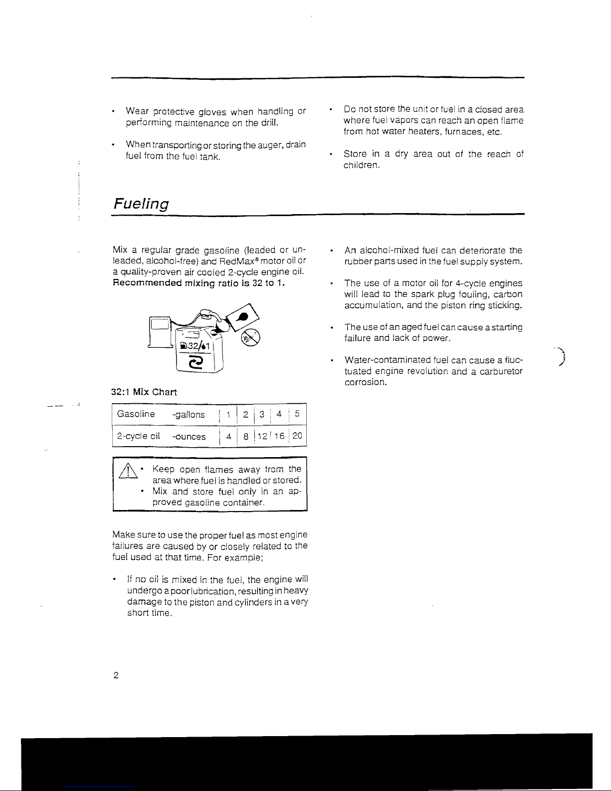
Mix a regular grade gasoline (leaded
or
un-
leaded, alcohol-free) and
RedMax~
motor oil
or
a quality-proven air cooled 2-cycle engine oil.
Recommended
mixing ratio is 32 to 1.
32:1
Mix
Chart
5
-g_a~I_lo_n_s
I
2
3
4
i
I Gasoline
I
1
I
,
!
__
---'_-'-_'----:---j
'!
[ 2-cycle oil -ounces
L1
8
112!
16
20
I
: I
I
A'
Keep open flames away from the
area where fuel
is
handled or stored.
• Mix and store fuel only
in
an ap-
proved gasoline container.
Make sure to use the proper fuel as most engine
failures are caused by
or
closely related to the
fuel used at
that
time. For example;
If
no oil
is
mixed
in
the fuel, the engine will
undergo a poor lubrication, resulting
in
heavy
damage to the piston and cylinders in a very
short time.
2
An alcohol-mixed fuel can deteriorate the
rubber parts used
in
the fuel supply system.
The use
of
a motor oil for 4-cycle engines
will lead to the spark plug fouling, carbon
accumulation, and the piston ring sticking.
The use of an aged fuel can
cause
a starting
failure and lack of power.
Water-contaminated fuel can cause a fluctuated engine revolution and a carburetor
corrosion.
Page 4
Operation
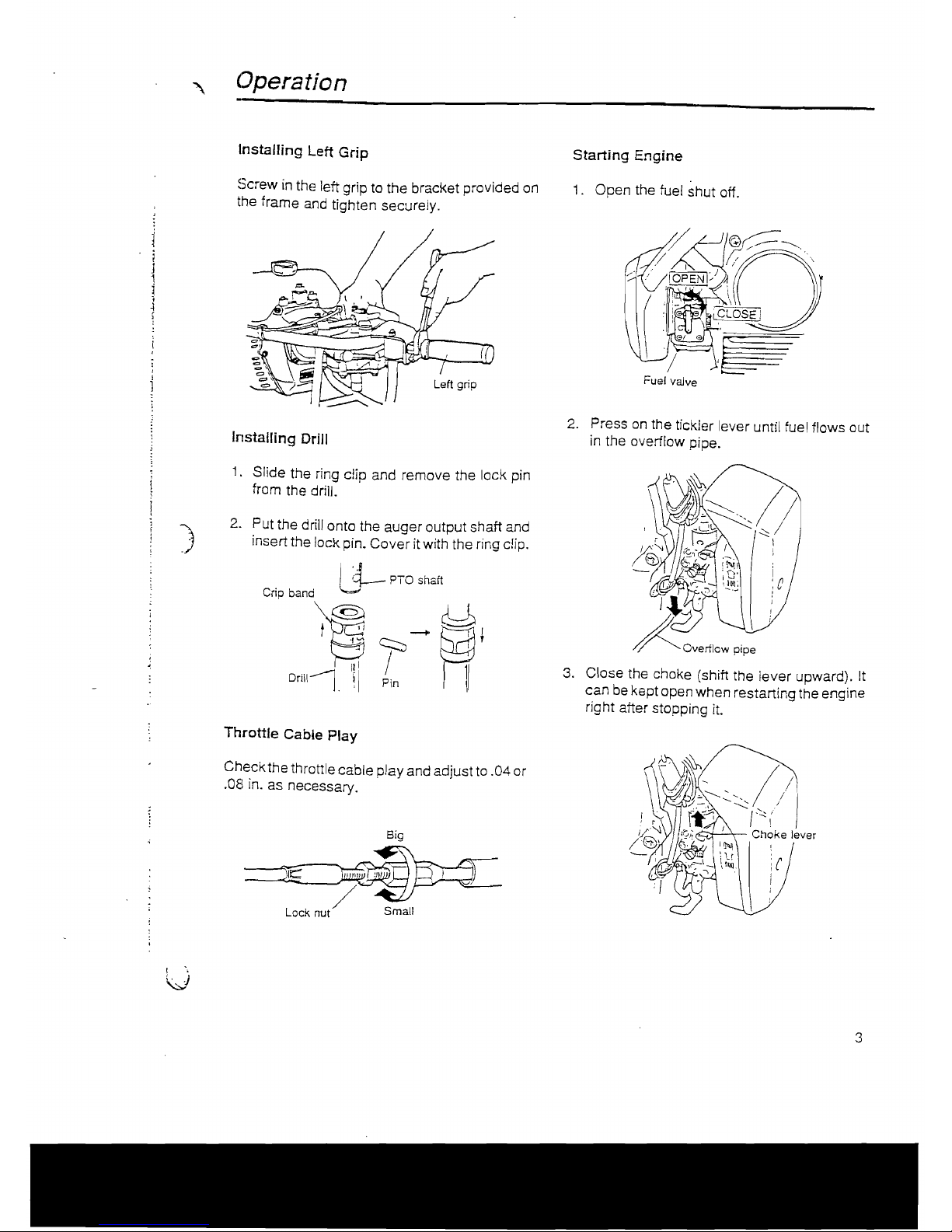
Installing Left Grip
Starting Engine
Screw
in
the left grip to the bracket provided on
1.
Open the fuel shut off.
the frame
and
tighten securely.
Fuel
vaJve
2. Press
on
the tickler lever until fuel flows out
Installing Drill
in the ovetilow pipe.
1.
Slide the ring clip and remove the lock pin
from the drill.
2. Put the drill onto the auger output shaft and
)
insert the lock pin. Cover it with the ring clip.
L3--
PTO shaft
Cc;p
b,"d
~
c:::::::,/
--+
I III
3.
Close the choke (shift the lever upward). It
Drill-----l
!I Pin
can
be
kept open when restarting the engine
right after stopping
it.
Throttle Cable Play
Check the throttle cable play and adjust
to
.04 or
.aEl
in. as necessary.
Big
I •
V
3
Page 5

4. Hook
up
the throttle lever in the starting
position.
L.ock
spring
5.
While supporting the auger with your left
waist and left hand as shown
in
the figure,
pull the starter rope, first lightly and add
force when compression is felt.
I!\
Keep the drill
clear
of everything
.
a.
round it
as
it will start rotating upon
starting of engine.
~
6.
When the engine has started. gradually open
the choke and release the throttle lever.
7. Allow the engine to warm up for a half
minutes before starting operation.
4
When re-starting immediately after stopping the engine. keep the choke open.
If the engine won't start after repeated attempts,
it may be overfed with fuel.
Remove and dry the spark plug, and try
to start again with the choke open.
Stopping Engine
Release the throttle lever and press on the red
button until the engine comes
to
a complete
stop.
Drilling
Keep a firm grip of the auger at all times
on
a wide stance and by holding the handle with
both hands.
A reacting motion may occur on the auger
when spinning drill has hit on stones or tree
roots under the ground. Always hold the
auger securely
to
control such motion.
Page 6

Start drilling with haJf-throttle, and gradually
increase the engine speed so that the drill
may get into the ground smoothly.
I
1
When the drill has been caught
in
the ground
and cannot
be
pulled out, stop the engine
and rotate the auger counter-clockwise.
1
J
jWaintenance
Adjustment of Idling
Spee<:i
The engine idling speed has been preset at the
factory
to
the
normal condition.
When it
is
too
low
or
too
high, adjust the idle
adjustment screw
on
the carburetor.
\
Idle adjusting screw
)
J
,
..
Before cleaning, inspecting or
re-
pairing the auger, make sure that the
engine has stopped and cooled
down. Disconnect the spark plug
terminal to avoid accidental engine
starts.
Daily Inspection
Check
all
nuts and screws are securely
tightened and no parts are missing.
Check for leakage of fuel.
Periodical Inspection
Check the air filter every 50 hours of use or
more frequently
if
used under very dusty
condition, and clean the element
in
warm
soapy water
as
necessary. Dry completely
before installing.
Check the spark plug every 50 hours of use
and clean the gap with a wire brush. The gap
should
be
set
to
.025 in. When replacing with
a new plug, use a
Champion RCJ 8Y or
NGK
BPMR
6A.
.024'
5
Page 7

Fuel Filter
Check oil level of the gear box every
50
hours of use and change with new oil
as
A clogg,:d fuel filter can cause lack of power and
necessary. (SAE #80 - 90).
poor pickup. Check the fuel filter every
25
use
hours.
1.
With a small wire hook, pull the fuel line
and
filter out of tank.
2.
Disconnect the
fi1ter
assembly.
3.
If
necessary, replace with new filter
or
clean
by blowing air inside out after spraying a
carburetor cleaning solvent.
Spark Arrester
This en!;line
is
equipped with a spark arresting
screen at the exhaust port. Check periodically
to
see if it
is
in
good condition, especially when
your machine
is
to be used on any forest covered, brush covered, or grass covered unimproved land.
In
the State of California the above
is
required
by
law (Section 4442 of the California
Public Resources Code).
1.
Remove the muffler guard and pry off the
spark arrester from the exhaust port.
2.
Clean the metal screen with a wire brush.
If
damaged, replace with new one.
~~
rr
~
!I~
~
.. I
c:=I[)
?3:\~
======;!J
©
-=~==::rJ==/
\ /
Muffler
auard
"--
Spark
arreSI~r
6
Recommended change interval:
1st : After 50 hours of use
2nd and on : Every 100 hours of use.
Disconnect the engine from the gear box
and check the clutch condition every 100
hours of use. Wipe off oil attached
to
the
drum and shoes, and replace parts with a
new
one if found to be worn.
Before
Long~term
Storage
Drain fuel tank and run the engine out until
all fuel
in
the carburetor
is
used up.
Remove the spark plug and drop a spoon of
2 cycle oil into the cylinder.
Crank
the engine
several times and replace the plug. Pull
starter until compression is felt.
Page 8

Specifications
..
~
I
Model Name
I
I
Engine:
I
I
Displacement
cu.
in
(cc)
Maximum power
HP
Carburetor
I
Ignition system
Spark plug
Starter
I
i
Fuel
i
i
Fuel tank capacity
fl.QZ
(lit)
I
Transmission
Gear box lubricant
I
Reduction ratio
I
Grip span
in
(mm)
I
Overall dimension:
Length
Width
Height
in
(mm)
in
(mm)
in
(mm)
Dry
weight w/o drill
Ibs
(kg)
,
I
Adaptable drill size:
I
Diameter
in
(mm)
I
AG431
2.53 (41.5)
2.02 at 7000
rpm
Diaphragm type (TK)
Electronic (T.C.!.)
Champion RCJ-8Y
Recoil starter
2 cycle oil premixed gasoline (32:1)
34
(1.0)
Centrifugal clutch,
worm gear reduction
Gear
oil SAE#80-90
45:
1
22.8 (580)
24.8 (630)
11.3 (287)
11.7 (298)
20.0 (9.1)
1.6
to
8 (40
to
200)
Specifications are subject
to
change without notice.
7
Page 9

Service Parts
Ust
Fig. 1
ENG
INE
GROU
P
. not
jncrvldu~
Numoar
COlumn
are supplied.
an
numOer.
Those
Nota:
an
assam
Oly.
... in
Iha
column
Pat1
ara nol
lor
assemoly
p
rd
uOll.
Out
Tha
pans 5indlcata
marl<s
seePlaase suppllad
ally
out
a
'OP'
in Ina
Re
@--'17
. d oy Ihe Remarxs . wrth
stanoa
pans
WIth
saoarara orcer.
:...
avauaDle
by
0+-118
125 @l
©-J
129
:.
.---,'
.
116
' "
'1/
;n
,,---,"
~
4138
/>--",
'
./«
/
~
/\~,y;.
:
II
/,
~/'i,
"
~<Q
-
'17@!%
/~.c-=
<
"~\:".
'~-J
",[('
"'"
" " "
if
'",
142
~o
,:"~-
I Vi'
(!j'"
L-",
",
I
34
~
39
42
" .
"\
'::A"",
'
"i&C/:uG~
// "
16
r:,' a
fc:,;~[7\I5\"
,,/
'~:i
-----~~
\ \
46
55
3~
~
• ,
"
F-
'" ", @
,,-"
I'Cl
"\'
_:
........
I
l}-"
\~
(y ,•.
"
'r-U
c::",
\\
'
//~,.
~74
\
~
"':;,'i~f~4;~'~,
-\'
28~
29
'00-
-1
's--...;
~>O,
-
'"
4
_
30
>0
""
''-'
'---Oftt-~-
//
-
-v"'...-
11;-----105 I '
'.
>0'
, /
'.
:gj~::
~lt~:~lLr-~6
1
97
(!l)
~
113
.
51
~-84
/.
_"
I"/,,,
\
"
~'K-96
.~.
'~~~
",~~
",
'
...
' 110
I
.2---25
11'
Page 10

.~
.,
1
~
I
I
lnaex
I
PartNU_!
101'(
1*'1
Re_
Descr1ptJon
Iie_
1
Index
I
f>artNumber
OMo1pt1on
0
';:.:'1
Remeno
No.
"nn
I
117'9-7527 I
SCREW
66
1
1
1400-12112
1
CYUNDER
1400-75160
67
ROPE
2
1
1400-13121
.1
GASKET
1400-75170
KNOB
ea
3 1
1420-131
:JO
1
GASKET
1179-75340
CAP
69
4
I
1400-13150
1
GASKET
1400-.5211
70
PULLEY,
Sla11er
1
5
1
1420-13160
INSULATOR
1428--.5411
71
LABEL
1
6
3310-12280
4
BOLT
1400-75510
SCREW
72
4
138
0260-:30525 2
SCREW
7
0260-30540
2
SCREW
14:iD-81
000
CARBURETOR
ASS'Y
1
7410108
8
1421-15110
I
MUFFLE:R
74
BODY. c:arnurelor
·142Q-810oo
'139
I
1421-15120
1
SPARK ARRESTER
CAp,boay
1650-81122
75
I
9
1400-15410
I
COVER. mutfler
1420--81480
76 DIAPHRAGM ASS'Y
I
10
1400-13142
1
GASKET
1101-81950
n PACKING. diaohragm
11
1
1140-51230
2
WASHER
1420-81150
78
YALVE. tI1mltle
I
12
0212-50665
BOLT
1335-81070
79 RECEIVE, lhrottle spnng
I
I
13
4
1400-15510
SCREW
2
I
103:8-81001-29
80
SCREW, aojUst
I
I
1650-81250
81
SPRING. adjust
=-ew
'14
1
I
1400-21100
CRANK
CASE
COMp
1420-81271
82 SCREW, M.J
adjust
"5
1
1400-21140
1
GASKET
1420-81370
83 SPRING. M,J
adjust
screw
1
'16
06030-06202
2
BEARING
1420-81490
COVER.
diapn"'llm
84 1
'17
1520--21220
1
SEAL
1420-81420
85 HOLDER. needle
Jel
I
'Ill
1
04065--C3515 RING
1420-81410
JET, needle
86
1
19
1400-21220
1
SEAL
1420-81730
PACKING, pumo
87
1
~~O
4
0260-00530
SCREW
1420-81720
DIAPHRAGM,
~mp
8B
1
1101-81190
89
CUP.
jot needle
1
~~1
1400-31111
I
COVER. t3n
1420-81180
NEDl£,jet
1
90
~2
4
0263-60520
SCREW
,
1325-81060
91 SPRING, Ihrottle
I
23
1100-72120
GROMMET
OZSO-10310
92
SCREW
2,4
4
1400-32110
1
COYER, "Yonder
1420-81801
93
PUMP COVER ASS'Y
1
25
1400-15510
2
SCREW
3422-81130
CAP'
S4
1
26
I
1633-31120
LABEl
1130-81170
95
YALYE ASS'Y
1
1
1400-15510
"lQ
SCREW
0260-103C8
SCREW
96
4
142
I
1600-86130
CLAMP, pipe
1420-81510
97
LEVER, lid<Ier
1
1420--8
1520
98
SPRING.
tlcI<Je,
I
27
1400-41111
1
PISTON
0260-00408
99
SCREW
1
28
1400-41220
2
RING, piston
1420-81530
100
COU..AR
1
Z9
1400-41310
1
P'N.
piston
103
0260-00306
SCREW
I
3iJ
33-SO-41320 2
RING
104
1100-81461
PIN, hinge
1
31
1
1400-41410
BEARING
1100-81440
105
YALYE, needle
1
3:2
2616-41510
2
WASHER. thrust
106
1420-814:30
SP RING, hinge
1
3:3
1400-4ZOO1 1
CRANK
SHAFT
COMp.
1420-81450
107
HINGE, valve
I
:J.l
0-1
1300-42410
SHIM
1420-81620
108
CAP,
M.J
saew
I
3S
1000-43240
I
KEY
1420--85180
109
PIPE
3lj
I
0290-21025
I
WASHER
3:1'
01641-21016
WASHER 2
1421-8:2002
Cl..E.ANER
ASS'Y
11010
113
1
311
11ClO-43231
NUT 2
110
BODY, Cleaner
"1421-82002
I
,
11
140C---321
:JO
ELEMENT
1
3~1
1400-511'0
SHOE 2
112
"1421-82002
COYER. cleaner
4(1 I
1200-5121
I
SCREW 2
113
1133--82060
LABEL
41
I
1400·51220
1
SPRING. clutch
114
0260-30422
SCREW
4"
..
2
1200-51230
WASHER 2
1423--831
00
llS
CABLE
CaMP.
4;;1
1
1200-51240
WASHER 2
142O-a5OCl3
TANK
ASS'Y
11610
121
4-ol.
1
1400-71110
I
ROTOR
116
TANK
"1420-85003
I
4S to
41 &.14
1650-71200
1
COILASS'Y
1~
4S
-'650-71200
1
1117
&
118
I
COIL
I
CAP
ASS-Y
117
CAP
46
1
\"1600-85202
1400-71220
1
CORD
1600-8$302
YALVECOMp.
118
47
I
1400-71230
1
CAP
FILTER COMp,
119
3306--a5400
14'1
1
I
I
1650-71241
1
CORD
\ 420--85400
pIPECOMp.
120
46
1400-71311
UNIT 1
1260-85450
121
CUP
I
49
3320-7221
I
1
GROMMET
I
1063--861
:JO
122
CUP
50
1100-72120
1
I
GROMMET
125
16ClO-86120
SCREW
51
3
1400·721
I 1
1
CAP, plug
1400-86213
127
SUPPORT. tanK
52
1
1400-72121
SPRING I
14lJ()-85250
128
COU..AR
53
I
1216-73110
Champion
1
SPARK PLUG
14lJ()-8B250
129
COLLAR
Re.;
8Y
2
54
1400-75510
SCREW
3
55
0250-30516
SCREW
2
56
2031-81610
SWITCH
1
57
1400-72250
BRACKET.
swnCJ1
1
14(}()-72310
58
CLAMP 1
1400-75100
591069
1
RECOIL
ASS'Y
59
·,400-75100
CASE I
60
1400-75120
REEL I
61
1400-75130
SPRING,
SPiral
1
62
1400·75140
RATCHET
1
63
1180-75251
SPRING, Inetlon
1
64
1179-75320
SPRING. return 1
65
I
1400-75180
RETAINER I
I
9
Page 11

Fig.2
A7TACHMENT GROUP
t-
3Q
~2B
r
Z9
/
2S
102
~
~
0",,-
~
--.~/
10'
~
@------90
~~
..
a8
..
f'i!
https://manualmachine.com/
\;
103
les
I
@
©-------93
c_
92
)
'-.~
91
0--S7
~~as
't-"
~i
-05
10
Page 12

1r::
x
j
P1lrt
r-!um""r
!
Dl!t~cr1pttcn
I
:Q'ty
per!
R.mark.3
i unrt !
2
1
1
1
,
6
1
1
1
I
1
I
,
I
,
1
1
1
1
1
1
1
2
0-3
4
1
2
2
2
4
4
1
1
I
2
2
2
<1
1
1
1
I
1
1
1
1
I
1
1
1
1
,
1
1
1
1
1
2
2
2
1
1
1
,
1
1
2
2
2
1
,
,
1
I
I
I
I
I
I
1321030
I
I
!37 to 39
1.320
....
31300
I
141
to
44
I
I
lop
461049
'3206,51100
I
lOP
50 to 57
'3206-52100
lOP
581055
1'3206.52200
I
I
lnaex ,
Pllrtllum_!
Oescrl
pllon
1
0
'1'1
per!
Romark>
No.
I
, urNt 1
65
I
3200·51140
CUP
1
320&-52:300
S'5O
DRILL
ASS'y
1
I
{5.S
In
.dlal
I
I
I
loe~."
BODY, dnll
I
1
'3206-52300
67
66
3206-52320 TIP. S150
1
01225-40620 SCREW
3
69
68
0280-10605
NUT
3
70
WASHeR
0290-206'5
3
BIT
3206-52330
1
71
PIN
3200-51130 1
73
72
CLIP
3200-51140
1
3206-52400
S200
DRILL
ASS'Y
OP
1410
5'
1
(7.9 In
,dis)
74
SODY, dnll
1
1'3206-52400
75
3202·52<120 TIP, 5200
1
76
01225-40625
SCREW
3
77
NUT
0280-10605
3
76
0290-20615
WASHER
3
79
BIT
1
80
3206·5=
PIN
3200-51130
1
al
3200-511
dO
CUI'
1
,
32ll6-<I, 1
00
OP 82
to
B7
1150
DRILL
ASS'y
(5.9
In
.dla)
I
BODY,dnll
1
'3206-51100
82
3206-61120
BLADE
1
83
BOLT
0225-5OE20
2
84
0280-10605
NUT
2
86
85
:3200-51130 PIN
1
87
3200-51140
CUP
1
L1DO
JOllfT
ASS')'
OPasto90
as
1
3204-53'00
'320<1-531
00
89
EXTENSION ROO
13.9
1
PIN
3200-51130 1
90
CLIP
3200·51140 1
lops,
to
93
L300
JOIIfT
ASS'Y
3204-53200 1
.
"XTENS10N
ROD
1
1'3204-53200
91
111.8 in.)
92
3200-51130
PIN
1
3200-511
dO
l CUP 1
93
1075-96100 i PULLER
ASS'Y
OP
102
101
1
1400-56210
SE"" BLOCK
01'
1
1400·96300
:
ROO
ASS"Y
01'
103 1
3206·91610
SPANNER
,04
1
lOP
:
1
.OP
3206·51620 ROO
105
i
I
I
!
:
!
:
I
1
~
,
i
1
I
i
1
t
j
)
I
\
1
i
l
1
1
I
1
1
i
...
1
1
J.
J
130
,
2
3
4
5
6
7
a
9
10
11
12
13
14
15
16
17
11~
lH
20
21
22
23
24
25
26
27
28
29
30
31
32
33
34
:l5
36
37
38
39
40
41
42
43
d4
45
46
47
48
49
50
51
52
53
54
55
56
57
5a
59
60
61
62
63
64
1400-86271
320!Hl102
3200-11202
1800-21261
3202-11260
0260-30620
06000-00304
3202-11311
3202'11320
3200-11330
07000-02012
04<)65-06220
3202-11361
2510-23230
0224..{)0610
3010-313S0
3205-21110
3200-21121
3200-21130
3206-21210
3205-21220
3200-21230
3202-21240
3200-21250
0225-50620
3204-31110
0225-10616
01642-20608
3209·31122
n06-31130
0225-50630
3206-14410
:l2O&-31201
3206-31211
3206-31220
1000-15150
0280-10605
0290·20615
3:204-31300
.
3541-14220
0281-11411
3892·41110
3206-91001
1820·91111
1030-91340
323S-91310
3540-91120
3SAD-93120
320&-51100
3202-51121
.3200-5
11
30
3200-51140
:\206-521
00
.
3206-52121
01225-40620
0280-10605
0290-20015
3206-52330
3'!00-51130
3200-51140
3206-52200
..
3206-52220
01
225-40620
028,"-10605
0290·20615
3206-52:>;30
320<J·5113O
CUSHION
GEAR
CASE COMP
COVERCOMP.
OIL SEAL
GASKET
SCREW
BEARING
RETAINER
OIL
SEAL
O-RING
O-RING
SNAP RING
PLUG
O-RING
BOLT
GASKET
WORM
COLLAR
DRUM
SHAFT
WHEi"L
WASHER
WASHER
SHIM
BOLT
HANDLE
BOLT
WASHER
HOLDER
SPACER
BOLT
L"VER,
THROTTLE
BRACKET
ASS'Y
BRACKET
MOUNT
NUT
NUT
WASHER
LEFT
HANDLE
COMP,
HANDLE, Ian
GRIP
NUT
NAMEPLATE
Toolsel
BAG
SCREWDRIVER
SOCKET
SPANNER
BAND
540
DRILL
ASS'Y
(1.6 In.
dla,j
BODY, drill
BIT
PIN
CLlP
560
DRILL
ASS'Y
(2.4 In
dis.)
BODY, anll
TIP.
560
SCREW
NUT
WASHER
BIT
PIN
CLIP
500
DRILL
ASS'Y
(3-5
In.
dla,)
BODY,
dnU
TIP,
590
SCREW
NUT
WASHER
BIT
PIN
11
Page 13

RedMaX':Bl
POWER
AUGER
MODEL
AG431
2-YEAR LIMITED WARRANTY
For two
(2)
years
[1
year if used commercially] from the date of original purchase of the model
AG431 unit, KOMATSU
ZENOAH
AMERICA INC. (the "Company"), through any RedMax:»
dealer, will repair or replace, free
of
charge, for the original purchaser, any part found to
be
defective
in
material and/or workmanship.
This
is
the
exclusive
remedy.
The purchaser shall bear costs
of
transporting the model AG431
to
and from the
RedMax~
dealers.
This warranty does not apply
to
those units which have been damaged by accident, mishan-
dling, alteration, abuse, improper lubrication, the use
of
any parts or accessories other than
those specified by the Company, or other causes beyond our control.
This warranty does not
coverthose
parts replaced for normal
wear
or harmless changes
in
their
appearance.
There
are
no
other
express
warranties.
IMPLJED WARRANTIES inclUding those of merchantability and fitness for a particular purpose
ARE
UMITED
to
one
(1)
year
from the original purchase date.
Liabilities
for
incidental
or
consequential
damages
under
any
and
all
warranties
are
excluded.
Some states do not allow limitations on how long an implied warranty lasts
orthe
exclusion or
limitation of incidental or consequential damages, so the above lim itation
or
exclusion may not
apply
to
you.
This warranty gives you specific legal rights, and you may also have other rights which vary
from state to state.
IMPORTANT:
You will receive a Warranty Registration Card at time of purchase.
Please keep the card and return
it
when sending your machine for a repair.
t)RedMar
KOMATSU
ZENOAH
AMERICA
INC.
1505
Pavilion
Place
Suite
A
Form
No.
21F-0312-70100-05
Norcross,
Georgia,
30093
Printed
in
Japan
11/90
 Loading...