

Red Lion N-Tron Series Manual Supplement

N-Tron® Series
CIP
NT24k
Software Manual | June 2016
TM
Installation & User Manual
TM
Products

M
ANAGEMENT
G
UIDE
COPYRIGHT
Copyright, © 2015-2016 Red Lion Controls, Inc.
20 Willow Springs Circle
York, PA 17406
All rights reserved. Red Lion, the Red Lion logo and N-Tron are registered trademarks of Red Lion Controls, Inc. All
other company and product names are trademarks of their respective owners.

P
REFACE
R
EVISED
D
RAWING NO
2016-06-15
. LP0990
PREFACE
Purpose This manual gives specific information on how to apply and use the CIP™ functions
on the N-Tron® series NT24k™ switches.
Audience The manual is intended for use by personnel who are responsible for operating and
maintaining network equipment; consequently, it assumes a basic working knowledge
of general switch functions and the Internet Protocol (IP).
Trademark
Acknowledgments
Red Lion Controls acknowledges and recognizes ownership of the following
trademarked terms used in this document.
• Ethernet™ is a registered trademark of Xerox Corporation
• EtherNet/IP™and CIP™ are registered trademarks of ODVA™
• All other company and product names are trademarks of their respective
ers
own
Certifications Red Lion Controls, Inc. ensures that this device meets all the ODVA technology and
standards guidelines for the Common Industrial Protocol (CIP) for industrial
automation.
Conventions The following conventions are used throughout this manual to show information:
Note: Emphasizes important information or
features or instructions.
calls your attention to related
Related Publications
and Document
Updates
This document is revised only at major releases and therefore, may not always
contain the latest product information. As needed, Tech Notes and or other product
documentation can be provided between major releases to describe any new
information or document changes.
Also, as part of the NT24k software, there is an online web-based help that describes
anagement related features.
all m
The latest online version of this document and all product updates can be accessed at
e Technical Resources page on the Red Lion web site at:
th
www.redlion.net/n-tron_documentation
N-Tron® Series NT24k™ CIP™ Manual - i -

P
REFACE
R
EVISED
2016-06-15
RAWING NO
D
. LP0990
Red Lion appreciates all comments that will help us to improve our documentation
quality. The user can submit comments through the Red Lion Customer Service.
Simply email us at
customer.service@redlion.net
References [1] The CIP Networks Library, Volume 1: Common Industrial Protocol (CIP™), Edition
3.16, Publication Number: PUB00001, Open DeviceNet™ Vendor Association, Inc.,
4220 Varsity Drive, Suite A, Ann Arbor, MI 48108-5006 USA
Revision History
[2] The CIP Networks Library, Volume 2: EtherNe
t/IP Adaptation of CIP™, Edition 1.17,
Publication Number: PUB00002, Open DeviceNet Vendor Association, Inc., 4220 Varsity Drive, Suite A, Ann Arbor, MI 48108-5006 USA
The following information lists the release history of this document.
Issue / Revision Date Content Description
July 2013 Initial version with support for switches in the NT24k product line.
August 23, 2013 Added missing documentation for the Power Configuration attribute
October 2013 Added faceplate installation instructions and quick reference guide.
March 2014 Added a description of the faceplate error messages.
October 2014 Added support for NT24k-8TX, NT24k-8TX-POE, and NT24k-16TX
November 2014 Added 802.1X port role.
March 2015 Revised face plates for NT24k-8TX, NT24k-8TX-POE, NT24k-16TX
of the N-Tron object.
switches.
switches.
Added support for:
NT24k-10FX2, NT24k-10FX2-POE
NT24k-10GX2, NT24k-10GX2-POE
NT24k-11FX3, NT24k-11FX3-POE
NT24k-11GX3, NT24k-11GX3-POE
NT24k-12FX4, NT24k-12FX4-POE
NT24k-12GX4, NT24k-12GX4-POE
NT24k-14FX6, NT24k-14FX6-POE
NT24k-14GX6, NT24k-14GX6-POE,
NT24k-12SFP-DM4, NT24k-12SFP-DM4-POE
November 2015 Revised to comply with updated ODV
May 2016 Added support for NT24k-16TX-POE switches
comply with updated Red Lion Controls technical documentation
standards.
- ii - N-Tron® Series NT24k™ CIP™ Manual
A requirements. Formatted to

P
REFACE
R
EVISED
D
RAWING NO
2016-06-15
. LP0990
N-Tron® Series NT24k™ CIP™ Manual - iii -

P
REFACE
R
EVISED
2016-06-15
D
RAWING NO
. LP0990
Disclaimer Portions of this document are intended solely as an outline of CIP methodologies to be
followed during the maintenance and operation of N-Tron® series NT24k equipment. It
is not intended as a step-by-step guide or a complete set of all procedures necessary
and sufficient to complete all operations.
While every effort has been made to ensure that this document is complete and
accurate at the time of release, the information that it contains is subject to change.
Red Lion is not responsible for any additions to or alterations of the original document.
Industrial networks vary widely in their configurations, topologies, and traffic
conditions. This document is intended as a general guide only. It has not been tested
for all possible applications, and it may not be complete or accurate for some
situations.
- iv - N-Tron® Series NT24k™ CIP™ Manual

T
ABLE OF CONTENTS
R
EVISED
2016-06-15
D
RAWING NO
. LP0990
TABLE OF CONTENTS
1 INTRODUCTION TO CIP™ COMPONENTS 1
CIP™ Components. . . . . . . . . . . . . . . . . . . . . . . . . . . . . . . . . . . . . . . . . . . . . 1
Electronic Data Sheets . . . . . . . . . . . . . . . . . . . . . . . . . . . . . . . . . . . . . . . . . . 1
CIP Objects . . . . . . . . . . . . . . . . . . . . . . . . . . . . . . . . . . . . . . . . . . . . . . . . . . 1
Identity Object. . . . . . . . . . . . . . . . . . . . . . . . . . . . . . . . . . . . . . . . . . . . . . . . . 2
TCP/IP Interface Object . . . . . . . . . . . . . . . . . . . . . . . . . . . . . . . . . . . . . . . . . 3
Ethernet Link Object . . . . . . . . . . . . . . . . . . . . . . . . . . . . . . . . . . . . . . . . . . . . 4
NT24k™ Object . . . . . . . . . . . . . . . . . . . . . . . . . . . . . . . . . . . . . . . . . . . . . . . 7
CIP Services. . . . . . . . . . . . . . . . . . . . . . . . . . . . . . . . . . . . . . . . . . . . . . . . . . 9
Accessing Data. . . . . . . . . . . . . . . . . . . . . . . . . . . . . . . . . . . . . . . . . . . . . . . . 9
Explicit Messaging . . . . . . . . . . . . . . . . . . . . . . . . . . . . . . . . . . . . . . . . . . . . . 9
I/O Connections . . . . . . . . . . . . . . . . . . . . . . . . . . . . . . . . . . . . . . . . . . . . . . . 9
2 ROCKWELL RSLOGIX 5000 - AOI 11
Material Prerequisites. . . . . . . . . . . . . . . . . . . . . . . . . . . . . . . . . . . . . . . . . . 11
Installation Instructions . . . . . . . . . . . . . . . . . . . . . . . . . . . . . . . . . . . . . . . . . 11
Software Installation Prerequisites . . . . . . . . . . . . . . . . . . . . . . . . . . . . . . . . 11
Summary of Installation Steps . . . . . . . . . . . . . . . . . . . . . . . . . . . . . . . . . . . 11
Configuration of RSLogix Project . . . . . . . . . . . . . . . . . . . . . . . . . . . . . . . . . 11
Importing an Add-On Instruction . . . . . . . . . . . . . . . . . . . . . . . . . . . . . . . . . 12
Add a Generic Ethernet Module to the I/O Configuration. . . . . . . . . . . . . . . 13
Add an Instance of the AOI in your Application.. . . . . . . . . . . . . . . . . . . . . . 15
Create and Configure Tags for the AOI . . . . . . . . . . . . . . . . . . . . . . . . . . . . 16
Verify the new RSLogix Configuration. . . . . . . . . . . . . . . . . . . . . . . . . . . . . 20
Input_Assembly Parameter . . . . . . . . . . . . . . . . . . . . . . . . . . . . . . . . . . . . . 21
Switch_Parameters Parameter. . . . . . . . . . . . . . . . . . . . . . . . . . . . . . . . . . . 22
Explicit Messaging Options . . . . . . . . . . . . . . . . . . . . . . . . . . . . . . . . . . . . . 23
Troubleshooting . . . . . . . . . . . . . . . . . . . . . . . . . . . . . . . . . . . . . . . . . . . . . . 23
Sample Project . . . . . . . . . . . . . . . . . . . . . . . . . . . . . . . . . . . . . . . . . . . . . . . 24
3 ROCKWELL RSLOGIX 5000 - TAG REFERENCE 25
Generic Assembly Tags . . . . . . . . . . . . . . . . . . . . . . . . . . . . . . . . . . . . . . . 27
NT24k Assembly Tags . . . . . . . . . . . . . . . . . . . . . . . . . . . . . . . . . . . . . . . . 30
System Fault Tags . . . . . . . . . . . . . . . . . . . . . . . . . . . . . . . . . . . . . . . . . . . . 32
CIP™ Tags . . . . . . . . . . . . . . . . . . . . . . . . . . . . . . . . . . . . . . . . . . . . . . . . . . 32
N-Tron® Series NT24k™ CIP™ Manual - v -

T
ABLE OF CONTENTS
R
EVISED
2016-06-15
RAWING NO
D
. LP0990
Identity Object. . . . . . . . . . . . . . . . . . . . . . . . . . . . . . . . . . . . . . . . . . . . . . . . 33
TCPIP Object . . . . . . . . . . . . . . . . . . . . . . . . . . . . . . . . . . . . . . . . . . . . . . . . 34
Ethernet Link Object . . . . . . . . . . . . . . . . . . . . . . . . . . . . . . . . . . . . . . . . . . . 34
N-Tron Switch Object . . . . . . . . . . . . . . . . . . . . . . . . . . . . . . . . . . . . . . . . . . 37
4 ROCKWELL FACTORYTALK - FACEPLATE INSTALLATION 39
Material Prerequisites. . . . . . . . . . . . . . . . . . . . . . . . . . . . . . . . . . . . . . . . . . 39
Installation Instructions . . . . . . . . . . . . . . . . . . . . . . . . . . . . . . . . . . . . . . . . . 39
Software Installation Prerequisites . . . . . . . . . . . . . . . . . . . . . . . . . . . . . . . . 39
Summary of Faceplate Installation Steps . . . . . . . . . . . . . . . . . . . . . . . . . . . 39
Configuration of FactoryTalk View Faceplate Displays . . . . . . . . . . . . . . . . 40
Configure a Shortcut to the PLC that is Running the Desired N-Tron Switch AOI
. . . . . . . . . . . . . . . . . . . . . . . . . . . . . . . . . . . . . . . . . . . . . . . . . . . . . . . . 40
Import Graphics into your Project . . . . . . . . . . . . . . . . . . . . . . . . . . . . . . . . . 41
Import Local Messages . . . . . . . . . . . . . . . . . . . . . . . . . . . . . . . . . . . . . . . . 43
Import Images . . . . . . . . . . . . . . . . . . . . . . . . . . . . . . . . . . . . . . . . . . . . . . . 44
Import HMI tags . . . . . . . . . . . . . . . . . . . . . . . . . . . . . . . . . . . . . . . . . . . . . . 45
Create Faceplate Display . . . . . . . . . . . . . . . . . . . . . . . . . . . . . . . . . . . . . . 45
Configure the Display Startup Macro.. . . . . . . . . . . . . . . . . . . . . . . . . . . . . . 45
Configure Display Parameter File. . . . . . . . . . . . . . . . . . . . . . . . . . . . . . . . . 48
Optionally Add Composite Switch Image to Display. . . . . . . . . . . . . . . . . . . 50
Optionally Add Specific Switch Image to Display . . . . . . . . . . . . . . . . . . . . . 50
FactoryTalk View SE Client Setup: . . . . . . . . . . . . . . . . . . . . . . . . . . . . . . . 51
5 ROCKWELL FACTORYTALK QUICK REFERENCE GUIDE 53
Introduction . . . . . . . . . . . . . . . . . . . . . . . . . . . . . . . . . . . . . . . . . . . . . . . . . 53
Home Display . . . . . . . . . . . . . . . . . . . . . . . . . . . . . . . . . . . . . . . . . . . . . . . . 54
Diagnostics Display . . . . . . . . . . . . . . . . . . . . . . . . . . . . . . . . . . . . . . . . . . . 56
Settings Display . . . . . . . . . . . . . . . . . . . . . . . . . . . . . . . . . . . . . . . . . . . . . . 58
Alarm Display . . . . . . . . . . . . . . . . . . . . . . . . . . . . . . . . . . . . . . . . . . . . . . . 59
Error Messages . . . . . . . . . . . . . . . . . . . . . . . . . . . . . . . . . . . . . . . . . . . . . . 60
Limited Warranty . . . . . . . . . . . . . . . . . . . . . . . . . . . . . . . . . . . . . . . . . . . . . 62
- vi - N-Tron® Series NT24k™ CIP™ Manual

L
IST OF TABLES
R
EVISED
D
RAWING NO
LIST OF TABLES
Identity Object Attributes 2
Identity Object Fault Bit Definitions 3
TCP/IP Interface Object Attributes 3
Ethernet Link Object Attributes 5
N-Tron Object Attributes 7
Summary of Supported CIP Services 9
Switch I/O and Configuration NT24k 9
N228Params.Control Tag Members 23
NT24k Switch and Data Types 25
Generic View of Assembly Data Received from an N-Tron Switch 27
2016-06-15
. LP0990
Generic View of Assembly Data Received from an N-Tron Switch 30
N-Tron Switch System Fault Tags 32
N-Tron Switch Identity Object Tags 33
N-Tron Switch TCPIP Object Tags 34
N-Tron Switch Ethernet Link Object Tags 34
N-Tron Switch Object Tags 37
Home Display Fields 54
Port Color/State Definition 56
Diagnostic Display Fields and Values 57
Settings Display Fields and Values 58
Alarm Display Fields and Values 59
Error Messages 60
N-Tron® Series NT24k™ CIP™ Manual - vii -

L
IST OF TABLES
R
EVISED
RAWING NO
D
2016-06-15
. LP0990
- viii - N-Tron® Series NT24k™ CIP™ Manual

I
NTRODUCTION TO
I/O C
ONNECTIONS
C
HAPTER
CIP C
OMPONENTS
1
EtherNet/IP™, better known as the Common Industrial Protocol (CIP™), was
designed for use in process control and industrial automation applications. CIP was
designed to provide consistent device access to eliminate the need for vendor specific
software for configuration and monitoring of individual devices.
Red Lion Controls N-Tron® series NT24k™ switches with CIP support can be used to
communicate with other industrial devices, such as Rockwell controllers.
1.1 CIP™ Components
The following CIP components are available with Red Lion Controls N-Tron series
NT24k CIP enabled switches.
R
EVISED
D
RAWING NO
2016-06-15
INTRODUCTION TO CIP™ COMPONENTS
. LP0990
1.1.1 Electronic Data Sheets
An electronic data sheet for each NT24k switch is provided.
In a Rockwell environment EDS files are installed using the “EDS Hardware
Installation Tool”. This allows NT24k switches to be recognized in an RSLinx
environment.
EDS and associated Icon files for each NT24k switch are included in the
CIP_Install_Kit.zip file in the subdirectory “Cip”.
1.1.2 CIP Objects
“Objects” are used to organize various information about the switch. There are four
types of objects provided. Three are specified by the ODVA™, and one is N-Tron
series specific:
• Identity object
• TCP/IP Interface object
• Ethernet Link object
• N-Tron switch object
Standard “services” are associated with objects. Services exist for reading an attribute,
setting an attribute, resetting a device, etc. See references [1] and [2] for specific
details.
The following sections describe the attributes associated with each object type, such
as attribute Id number and data format. All attributes can be read, but only some can
be set, as shown by the “Set” column.
N-Tron® Series NT24k™ CIP™ Manual - 1 -

I
NTRODUCTION TO
ONNECTIONS
I/O C
CIP C
OMPONENTS
1.1.2.1 Identity Object
The identity object class (Class code = 0x01) and instance attributes are implemented
as defined by CIP Vol 1, 5-2 [1]. There is one instance (1) of this object. Service code
(0x32) will get all attributes, including optional attributes.
attributes in the Identity object.
R
EVISED
2016-06-15
D
RAWING NO
. LP0990
Tab le 1-1 summarizes the
Table 1-1 Identity Object Attributes
ID Name Set Format Description
1 Vendor ID UINT (16) 1006. This is N-Tron’s ODVA EtherNet/
2 Device Type UINT (16) 0x0C. Communications Adapter
3 Product Code UINT (16) Switch product code:
4 Major Revision USINT (8) Major version of CIP implementation
Minor Revision USINT (8) Minor version of CIP implementation
5 Status WORD (16) Summary status of device. Bits:
IP Vendor ID
NT24k -RM= 24001
NT24k-DR16= 24002
NT24k-DR24= 24003
NT24k-8TX= 24004
NT24k-8TX-POE= 24005
NT24k-16TX= 24006
NT24k-16TX-POE= 24077
NT24k-10FX2= 24008
NT24k-10GX2= 24009
NT24k-11FX3= 24010
NT24k-11GX3= 24011
NT24k-12FX4= 24012
NT24k-12GX4= 24013
NT24k-14FX6= 24014
NT24k-14GX6= 24015
NT24k-12SFP-DM4= 24016
NT24k-10FX2-POE= 24017
NT24k-10GX2-POE= 24018
NT24k-11FX3-POE= 24019
NT24k-11GX3-POE= 24020
NT24k-12FX4-POE= 24021
NT24k-12GX4-POE= 24022
NT24k-14FX6-POE= 24023
NT24k-14GX6-POE= 24024
NT24k-12SFP-DM4-POE= 24025
Bit 0: if set, device has an owner
Bit 1: reserved
Bit 2: if set, device has non-default
configuration
Bit 3: reserved
Bits 4-7: Extended device status – not
used
Bit 8: Minor recoverable fault
Bit 9: Minor unrecoverable fault
Bit 10: Major recoverable fault
Bit 11: Major unrecoverable fault
Bits 12-15: reserved (see Ta bl e 1-2)
(see Identity Object Fault Tab le 1-2)
- 2 - N-Tron® Series NT24k™ CIP™ Manual

I
NTRODUCTION TO
I/O C
ONNECTIONS
CIP C
OMPONENTS
Ta bl e 1-2 defines fault bits within the Status attribute of the Identity Object.
R
EVISED
D
RAWING NO
2016-06-15
. LP0990
ID Name Set Format Description
6 Serial Number UDINT (32) Serial number of the device. This is the
last 4 octets of the base switch MAC
7 Product Name SHORT_STRING Switch Model Name.
EX: NT24k
15 Assigned_Name Set STRINGI This is the user assigned switch name
17 Geographic_Location Set STRINGI This is the user assigned switch
cation
lo
Table 1-2
Identity Object Fault Bit Definitions
Bit Called Definition
8 Minor Recoverable Fault Power supply 1, Power supply 2
, N-Ring Full, System, Port
utilization, Temperature, N-Link partner is down, N-Link
integrity fault
9 Minor Unrecoverable
ult
Fa
Configuration device error
10 Major Recoverable Fault N-Ring partial low, N-Ring partial high, N-Ring multiple
agers, Boot loader version, N-Link partner port
man
unknown, N-Link multiple masters, N-Link control fault, NLink configuration fault, Settings fault
11 Major Unrecoverable
t
Faul
none
1.1.2.2 TCP/IP Interface Object
The TCP/IP Interface object class (Class code = 0xF5) and instance attributes are
implemented as defined by CIP Vol 2, 5-3 [2]. There is only one instance (1) of this
object. Tab le 1-3 summarizes the attributes in the TCP/
Table 1-3 TCP/IP Interface Object Attributes
ID Name Set Format Description
1 Status DWORD (32) Interface status
2 Configuration
ability
Cap
DWORD (32) Interface capability flags. Bits:
IP Interface object.
Bit 0: interface configuration attrib not
configured
Bit 1: interface configuration attrib is
valid
Bit 0: BOOTP
Bit 1: DNS client capable
Bit 2: DHCP client capable
Bit 3: DHCP-DNS update capable
Bit 4: configuration is settable
Bit 5: through Bit 31 reserved
client capable
N-Tron® Series NT24k™ CIP™ Manual - 3 -

I
NTRODUCTION TO
ONNECTIONS
I/O C
CIP C
OMPONENTS
R
EVISED
2016-06-15
D
RAWING NO
. LP0990
ID Name Set Format Description
3 Configuration
Control
Set DWORD (32) Interface control flags
Bits 0-3:
0: use interface configuration
previously stored
1: get interface configuration via
BOOTP
2: get interface configuration via
DHCP
3: through Bit 15 reserved
4 =1 device shall resolve host
names by querying a DNS
server
4 Physical Link Object STRUCT of:
Path Size UINT (16) Size of Path
Path Padded EPATH Logical segments identifying the
physical link object
5 Interface
STRUCT of:
Configuration
IP Address Set UDINT (32) The device’s IP address
Network Mask Set UDINT (32) The device’s network mask
Gateway Address Set UDINT (32) Default gateway address
Name Server Set UDINT (32) Primary name server
Name Server 2 Set UDINT (32) Secondary name server
Domain Name Set STRING Default domain name
6 Host Name Set STRING Host name
8 TTL Value USINT TTL Value for EtherNet/IP multicast
packets. Default is 1. Range is 1-255
9 Mcast Config STRUCT of: IP multicast configuration
Alloc Control USINT Multicast address allocation control
word. Determines how addresses are
allocated
Reserved USINT Reserved for future use. Shall be 0
Num Mcast UINT Number of IP multicast addresses to
allocate for EtherNet/IP
Mcast Start Addr USDINT Starting multicast address from which
to begin allocation
13 Encapsulation
Inactivity Timeout
Set UINT Number of seconds of inactivity before
TCP connection is closed. 0 = Disable,
1-3600 = timeout in seconds, Default =
120
1.1.2.3 Ethernet Link Object
The Ethernet Link object class (Class code = 0xF6) and instance attributes are
implemented as defined by CIP Vol 2, 5-4 [2].There is one instance of this object per
switch port where instance 1 = port 1, instance 2 = port 2, etc. As per the CIP
specification, the get all service code (0x01) will get all attributes, excluding vendor
extensions. Service code (0x32) will get all attributes, including the N-Tron vendor
extensions.
Tab le 1-4 summarizes the attributes in the Ethernet Link object.
- 4 - N-Tron® Series NT24k™ CIP™ Manual

I
NTRODUCTION TO
I/O C
ONNECTIONS
CIP C
OMPONENTS
R
EVISED
D
RAWING NO
2016-06-15
Table 1-4 Ethernet Link Object Attributes
ID Name Set Format Description
1 Interface Speed UDINT (32) Interface speed currently in use.
2 Interface Flags DWORD (32) Interface status flags Bit map of
3 Physical Address ARRAY of 6
USINTs (8)
4 Interface Counters STRUCT of:
In Octets UDINT (32) Octets received on the interface
In Ucast Packets UDINT (32) Unicast packets received on the
In Nucast Packets UDINT (32) Non-unicast packets received on the
In Discards UDINT (32) Inbound packets received on the
In Errors UDINT (32) = 0. Not available.
In Unknown Protos UDINT (32) = 0. Not available.
Out Octets UDINT (32) Octets sent on the interface
Out Ucast Packets UDINT (32) Unicast packets sent on the interface
Out Nucast Packets UDINT (32) Non-unicast packets sent on the
Out Discards UDINT (32) Outbound packets discarded
Out Errors UDINT (32) = 0. Not available.
5 Media Counters STRUCT of:
Alignment Errors UDINT (32) Frames received that are not an
FCS Errors UDINT (32) Frames received that do not pass the
Single Collisions UDINT (32) Successfully transmitted frames which
Multiple Collisions UDINT (32) Successfully transmitted frames which
SQE Test Errors UDINT (32) = 0. Not available.
Deferred
UDINT (32) Frames for which first transmission
Transmissions
Late Collisions UDINT (32) Number of times a collision is detected
Excessive Collisions UDINT (32) Frames for which transmission fails due
Speed in Mbps (e.g., 0, 10, 100, 1000,
etc.)
interface flags. See section 5-4.3.2.1.
Includes Link status, duplex mode,
auto-negotiation status, etc
MAC address of switch port
interface
interface
interface but discarded
Inbound packets that contain errors
(does not include In Discards)
Inbound packets with unknown protocol
interface
Outbound packets that contain errors
integral number of octets in length
FCS check
experienced exactly one collision
experienced more than one collision
Number of times SQE test error
message is generated
attempt is delayed because the
medium is busy
later than 512 bit times into the
transmission of a packet
to excessive collisions
. LP0990
N-Tron® Series NT24k™ CIP™ Manual - 5 -

I
NTRODUCTION TO
ONNECTIONS
I/O C
CIP C
OMPONENTS
R
EVISED
2016-06-15
D
RAWING NO
. LP0990
ID Name Set Format Description
MAC Transmit Errors UDINT (32) = 0. Not available.
Frames for which transmission fails
due to an internal MAC sub layer
transmit error
Carrier Sense Errors UDINT (32) = 0. Not available.
Times that the carrier sense condition
was lost or never asserted when
attempting to transmit a frame
Frame Too Long UDINT (32) Frames received that exceed the
maximum permitted frame size
MAC Receive Errors UDINT (32) = 0. Not available.
Frames for which reception on an
interface fails due to an internal MAC
sub layer receive error
6 Interface Control STRUCT of:
Control Bits Set WORD (16) Interface Control Bits. Includes auto-
negotiation and duplex settings.
Forced Interface
Speed
Set UINT (16) Speed at which the interface shall be
forced to operate. Speed in Mbps (10,
100, 1000, etc.)
7 Interface Type USINT (8) Type of interface: twisted pair, fiber,
internal, etc
8 Interface State USINT (8) Current state of the interface:
operational, disabled, etc
9 Admin State Set USINT (8) Administrative state: enable, disable
10 Interface Label
SHORT_STRI
NG Human readable identification: TX1,
FX1, GB1, A4, C8, etc
100 Interface Description
SHORT_STRI
NG Human readable description. For
example: Port 1 - 10/100 Mbit TX
Port 15 - 100 MBit FX
101 Interface Utilization USINT (8) Percentage of entire interface
bandwidth being used (0-100)
102 Utilization Alarm
Upper Threshold
103 Utilization Alarm
Lower Threshold
Set USINT (8) Upper percentage at which to declare
utilization alarm (0-100)
Set USINT (8) Lower percentage at which to declare a
utilization alarm (0-100)
104 Broadcast Limit Set USINT (8) Broadcast limiting percentage (0-100).
(BPCL)
105 TX Unicast Packet
Rate
106 RX Unicast Packet
Rate
107 TX Multicast Packet
Rate
108 RX Multicast Packet
Rate
109 TX Broadcast Packet
Rate
110 RX Broadcast Packet
Rate
UDINT32 Number of TX unicast packets per
second
UDINT32 Number of RX unicast packets per
second
UDINT32 Number of TX multicast packets per
second
UDINT32 Number of RX multicast packets per
second
UDINT32 Number of TX broadcast packets per
second
UDINT32 Number of RX broadcast packets per
second
111 TX Multicast Packets UDINT32 Total number of TX multicast packets
112 RX Multicast Packets UDINT32 Total number of RX multicast packets
- 6 - N-Tron® Series NT24k™ CIP™ Manual

I
NTRODUCTION TO
I/O C
ONNECTIONS
CIP C
OMPONENTS
113 TX Broadcast
114 RX Broadcast
115 Port Role UDINT32 Bit mask of port roles
1.1.2.4 NT24k™ Object
The N-Tron object (Class code = 0xC0) is a vendor specific object and is implemented
as defined by CIP Vol 1, 4 [1]. There is only one instance (1) of this object.
summarizes the attributes of the N-Tron object.
R
EVISED
D
RAWING NO
ID Name Set Format Description
UDINT32 Total number of TX broadcast packets
Packets
UDINT32 Total number of RX broadcast packets
Packets
Bit 0: RSTP
Bit 1: N-Ring
Bit 2: N-Link Control
Bit 3: N-Link Partner
Bit
4: N-Link Coupler
Bit 5: 802.1X
Table 1-5 N-Tron Object Attributes
2016-06-15
. LP0990
Table 1-5
ID Name Set Format Description
1 Device Up Time UDINT (32) Number of seconds since device was
powered up
2 Port Count UDINT (32) Total port count
3 Valid Ports LWORD (64) AB:
DINT[2]
0 = Invalid Port, 1=Port Exists on device
Bit 0: Port 1
Bit 1: Port 2 etc
4 Global Admin Status LWORD (64) AB:
DINT[2]
0 = Port Disabled, 1 = Port Enabled
Bit 0: Port 1
Bit 1: Port 2 etc
5 Global Link Status LWORD (64) AB:
DINT[2]
0 = Link Down, 1 = Link Up
Bit 0: Port 1
Bit 1: Port 2 etc
6 System Faults DWORD (32) Bit 00: Power Supply 1
Bit 01: Power Supply 2
Bit 02: N-Ring Fault (complete)
Bit 03: N-Ring Partial Fault (low port)
Bit 04: N-Ring Partial Fault (high port)
Bit 05: N-Ring Multiple Managers
Bit 06: System error
Bit 07: the configuration on an installed
configuration device is invalid
Bit 08: N-Link Fault
Bit 09: Boot loader version mismatch
Bit 10: Port Utilization Alarm
Bit 11: Temperature Alarm
Bit 12: Settings fault
7 IGMP Querier Status USINT (8) Query Status:
0 = Disabled, 1 = Active (manual),
2 = Active (Auto), 3 = Backup (Auto)
[enabled but not active]
8 IGMP Version USINT (8) IGMP Version (V1, V2, V3, etc.)
9 IGMP
Resource Usage
USINT (8) Percent of maximum capacity. Takes
into account the number of groups used
per max groups and any other possible
resource limitations (0-100)
N-Tron® Series NT24k™ CIP™ Manual - 7 -

I
NTRODUCTION TO
ONNECTIONS
I/O C
CIP C
OMPONENTS
R
EVISED
2016-06-15
D
RAWING NO
. LP0990
ID Name Set Format Description
10 IGMP Active Querier UDINT (32) IP of the active IGMP querier
11 CPU Usage USINT (8) Percent of usage (0-100)
12 Class 1 Connections UINT (16) Number of CIP EtherNet/IP class 1
(multicast) connections
13 Class 3 Connections UINT (16) Number of CIP EtherNet/IP class 3
(unicast) connections
14 Temperature Alarm
Upper Threshold
15 Temperature Alarm
Lower Threshold
Set INT (16) Upper temperature (C) at which to
declare an alarm
Set INT (16) Lower temperature (C) at which to
declare an alarm
16 Contact Status BYTE (8) 2 Bits per contact. 00=Not Present,
01=Open, 10=Closed
17 Temperature_C INT (16) Temperature in degrees C. 0x7FFF =
Not Supported on device
18 Temperature_F INT (16) Temperature in degrees F. 0x7FFF =
Not Supported on device
19 Reset MIB Counts Set LWORD (64) Reset port MIB counters.
(1 bit per port to reset)
20 Device MAC
Address
ARRAY of 6
USINTs (8)
MAC address of device
21 Device Role UDINT (32) Bit mask of device roles
Bit 0: N-Ring Manager
Bit 1: N-Ring Member
Bit 2: N-Ring AutoDetect
Bit 3: N-Link Master
Bit 4: N-Link Slave
Bit 5: N-Link Coupler
22 Config Device Status BYTE (8) 0 = Not Supported, 1 = Not Present,
2 = Present
23 System
Configuration
Set UDINT (32) Bit mask of system config. Bits=
Bit 0: GET: Changes have been made
that have not been saved
SET: Save system configuration
to flash.
Bit 1: GET: Changes have been made
that require a reboot to take
effect.
SET: Shutdown and reboot
device*
24 System Firmware
Version String
25 System Boot Loader
Version String
SHORT_STRI
SHORT_STRI
NG Human readable representation of
firmware version string.
NG Human readable representation of boot
loader version string
26 System Fault String STRINGI Human readable representation of error
status. May contain multiple errors.
Length is contained as part of the
STRINGI data type
27 Power Configuration UDINT (32) 4 Bits per power supply
0000 = DC Power, 0001 = AC Power,
1111 = Unknown.
Power supply 1 configuration is in bits
0-3
Power supply 2 configuration is in bits
4-7
* ID 23 Bit 1 SET: This feature will be removed in a future release.
- 8 - N-Tron® Series NT24k™ CIP™ Manual

I
NTRODUCTION TO
I/O C
ONNECTIONS
CIP C
OMPONENTS
1.1.2.5 CIP Services
Ta bl e 1-6 presents a summary of the supported services as defined by CIP Vol 1,
Appendix A: Explicit Messaging Services
R
D
RAWING NO
[1].
Table 1-6 Summary of Supported CIP Services
EVISED
2016-06-15
. LP0990
Service
Code
1 Get_Attributes_All yes yes yes yes
5 Reset Yes – r eset
14 Get_Attribute_Singleyes yes yes yes
16 Set_Attribute_Single Attributes
Vendor
Specific
50 Get_All_Attributes –
Object
Specific
76 Get_And_Clear Attributes
Service Description Identity TCP/IP Ethernet
switch or
restore
factory
guration
confi
Attributes
3,5
including vendor
defined attributes
,17
15
yes yes
Link
Attributes
6,9, 102-
104
4,5
1.1.3 Accessing Data
N-Tron
Attributes
14,15,19,23
1.1.3.1 Explicit Messaging
Explicit messaging refers to a request/response form of communications over a CIP
(TCP/IP) connection. Applications can use explicit messaging, for example, to invoke
the “Get All Attributes” service and read all attributes of the Identity object.
1.1.3.2 I/O Connections
I/O connections are used to send data (grouped in assemblies) between devices
periodically. The interval between sends is the “Requested Packet Interval”, or RPI.
The N-Tron Series switch assemblies (Input, Outpu
Ta bl e 1-7.
Table 1-7 Switch I/O and Configuration NT24k
Switch Assembly Number Size (bytes)
Input (to switch)* 101 4
Output (from switch) 102 104
Configuration* 103 0
* - not currently used
N-Tron® Series NT24k™ CIP™ Manual - 9 -
t, and Configuration) are defined in

I
NTRODUCTION TO
I/O C
ONNECTIONS
CIP C
OMPONENTS
In an RSLogix 5000 environment, these assemblies are configured in the “Connection
Parameters” panel of the Generic Ethernet Module.
More information is contained in Chapter 2 Rockwell RSLogix 5000 - AOI for
Add-On Instruction installation.
Note: Input and output assemblies are reversed.
R
EVISED
D
RAWING NO
2016-06-15
. LP0990
- 10 - N-Tron® Series NT24k™ CIP™ Manual

R
EVISED
2015-11-13 R
D
RAWING NO
C
HAPTER
OCKWELL
. LP0990 M
2
ROCKWELL RSLOGIX 5000 - AOI
2.2 Material Prerequisites
• N-Tron® Series Switch
• RSLogix Add-On Instructions (AOI)
2.3 Installation Instructions
2.3.1 Software Installation Prerequisites
• RSLogix 5000 version 17 or later
RSL
OGIX
5000 - AOI
ATERIAL PREREQUISITES
• N-Tron switch with firmware version that includes CIP support
2.3.2 Summary of Installation Steps
1. Import the Add-On Instruction (AOI)
2. Add your N-Tron switch to the I/O Configuration tree
3. Add an instance of the AOI in your application
4. Create and configure tags for the AOI
2.4 Configuration of RSLogix Project
Note: The screen shots shown in the RSLogix5000 portion of this document
are taken from the RSLogix5000 demonstration project file “NTron_Demo.ACD” which is included in the CIP_Install_Kit.zip file
under the subdirectory “RSLogix5000”.
N-Tron® Series NT24k™ CIP Manual - 11 -
R
OCKWELL
C
ONFIGURATION OF
RSL
OGIX
5000 - AOI R
RSL
OGIX PROJECT
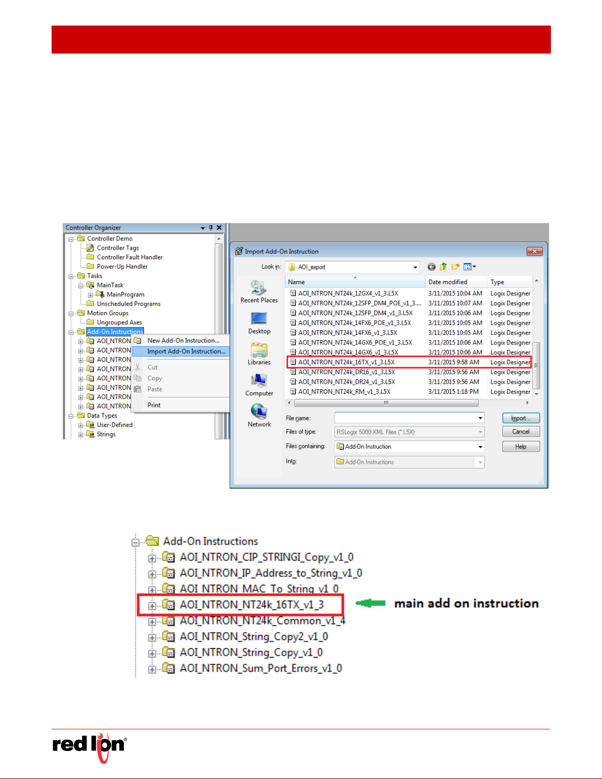
2.4.1 Importing an Add-On Instruction
All NT24k Add-On Instruction files are included in the CIP_Install_Kit.zip file in the
subdirectory “RSLogix5000\AOI_export”.
1. Open an RSLogix project.
2. Import the N-Tron Add-On Instruction (AOI).
3. In the controller organizer window, right click “Add-On Instructions” folder,
select
Tron_*.L5X files. Import an AOI for each switch type installed.
“Import Add-On Instruction” and browse to the folder containing AOI_N-
EVISED
2015-11-13
4. The Add-On Instruction tree showing an AOI for the NT24k switch, and several auxiliary AOIs which get loaded as
- 12 - N-Tron® Series NT24k™ CIP Manual
part of the main AOI.
 Loading...