

red lion MODULAR CONTROLLER SERIES, CSPID2S0, CSPID2T0, CSPID2SM, CSPID2TM User Manual
Bulletin No. CSPID1-H
1
7
13
1.24
(126.5)
4.17 (105.9)
4.98
(31.5)
C
US LISTED
C
US
Drawing No. LP0542
Released 05/11
Tel +1 (717) 767-6511
Fax +1 (717) 764-0839
www.redlion.net
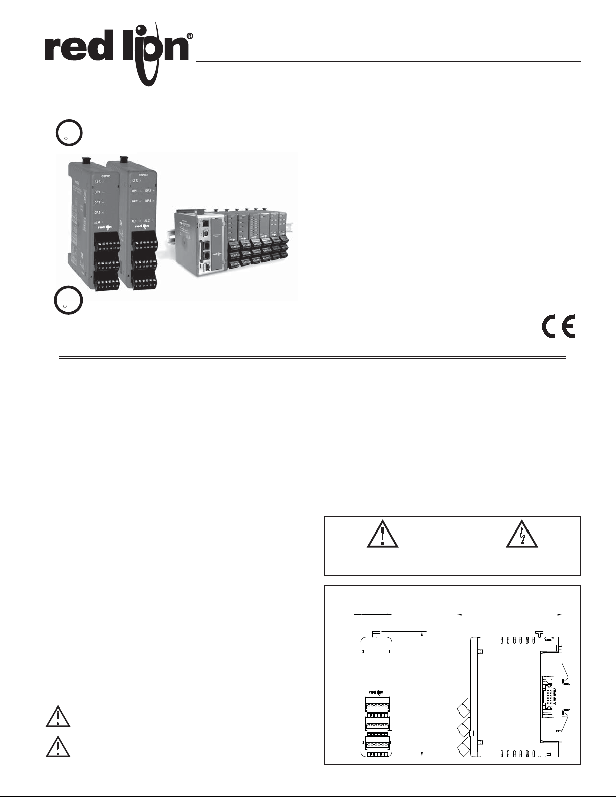
MODEL CSPID – MODULAR CONTROLLER SERIES PID MODULES
U
R
C
L
US LISTED
IND. CONT. EQ.
34AD
U
R
C
L
FOR USE IN HAZARDOUS LOCATIONS:
US
Class I, Division 2, Groups A, B, C, and D
LISTED
IND.CONT. EQ.
3PWL
For Model No. CSPID2S0, CSPID2SM, CSPID2T0, and CSPID2TM Only
DEDICATED SINGLE AND DUAL PID MODULES FOR THE
MODULAR CONTROLLER SERIES
HOT-SWAPPABLE REPLACEMENT REDUCES DOWNTIME
AUTO ADDRESSING MINIMIZES CONFIGURATION TIME
FULLY ISOLATED DESIGN PROVIDES RELIABLE OPERATION
PID CONTROL WITH REDUCED OVERSHOOT
UNIVERSAL INPUTS ACCEPT TC, RTD, 0-10 V and 0/4-20 mA
SIGNALS
ON DEMAND AUTO-TUNING OF PID SETTINGS
DC ANALOG OUTPUT (OPTIONAL, CSPID1 ONLY)
HEATER CURRENT INPUT (OPTIONAL) ENSURES DETECTION
OF HEATER CIRCUIT FAILURE
WINDOWS
®
CONFIGURATION SOFTWARE
GENERAL DESCRIPTION
The Model CSPID series modules are full featured PID controllers designed
for use with the Modular Controller Series. The CSPID1 is a single loop
controller, while the CSPID2 is a dual loop controller. The design of the system
provides a true modular PID control platform for multi-zone control applications.
The modules can accept a wide range of thermocouple, RTD, 0-10 V, 0/4-20 mA
signals. With multiple discrete outputs, plus an optional analog output (CSPID1
only), the CSPID modules can perform virtually any combination of timeproportioning or linear control for heat, cool, or heat/cool applications. The
discrete outputs may also be assigned to one of seven internal soft alarms. The
CSPID1’s optional linear output can be assigned to transmit virtually any
internal variable.
The CSPID modules connect and communicate via a backplane connection to
the CSMSTR Modular Controller Series Master. The CSMSTR, equipped with
serial ports as well as an Ethernet port, allows the system to share data with PCs,
PLCs, and SCADA systems. The Master supports any combination of up to 16
CS Series modules.
The CSPID modules are available with various discrete output combinations,
including relays, open drain MOSFETs, and triac outputs. For applications
requiring large loads to be controlled, several DIN rail mount relays are available.
The modules can operate in On/Off, P, PI, or PID control mode, and use an
on-demand Auto-Tune that establishes the tuning constants. The PID constants
may be fine-tuned through the serial or Ethernet interface. The modules employ
a unique overshoot suppression feature, which allows the quickest response
without excessive overshoot. The modules can also be operated in manual mode,
providing the operator with direct control of the output.
Internal power management circuits allow the modules to be replaced while
power is applied, which reduces downtime in the event of a relay failure. All
configuration information is stored locally within each module, as well as in the
Master, so replacement modules do not need to be configured.
The Modular Controller Series’ high density packaging and DIN rail
mounting saves time and panel space. The backplane connection provides power
and communication to the module and snaps easily onto standard top hat (T)
profile DIN rail.
WARNING - EXPLOSION HAZARD - SUBSTITUTION OF
COMPONENTS MAY IMPAIR SUITABILITY FOR CLASS I,
DIVISION 2
THIS EQUIPMENT IS SUITABLE FOR USE IN CLASS I,
DIVISION 2, GROUPS A, B, C, D, OR NON-HAZARDOUS
LOCATIONS ONLY
CONFIGURATION
The Modular Controller Series is configured with Windows® compatible
®
Crimson
provides a means of communication configuration, as well as commissioning
and calibration of new systems.
software. The software is an easy to use, graphical interface which
ALARMS
Each loop within the modules has seven internal “soft” alarms, which can be
assigned to trigger any output. This includes four process alarms, two heater
current, and one input fault alarm.
ANALOG OUTPUT OPTION (CSPID1 ONLY)
The optional DC Analog Output (10 V or 20 mA) can be independently
configured and scaled for control or re-transmission purposes.
CAUTION: Risk of Danger.
Read complete instructions prior to
installation and operation of the unit.
CAUTION: Risk of electric shock.
DIMENSIONS In inches (mm)
1

HEATER CURRENT MONITOR OPTION
The optional Heater Current Monitor input is useful for early warning of
heater degradation, or heater circuit failure. The input connects to a current
transformer with an output of 100 mA AC to ensure that proper heater current is
present when the control output is on, and that little or no current is present when
the output is off. This option provides immediate warning of a circuit short or
open, instead of waiting for a high or low temperature shutdown alarm.
SAFETY SUMMARY
All safety related regulations, local codes and instructions that appear in the
manual or on equipment must be observed to ensure personal safety and to
prevent damage to either the instrument or equipment connected to it. If
equipment is used in a manner not specified by the manufacturer, the protection
provided by the equipment may be impaired.
Do not use the controller to directly command motors, valves, or other
actuators not equipped with safeguards. To do so can be potentially harmful to
persons or equipment in the event of a fault to the controller. An independent
and redundant temperature limit indicator with alarm outputs is strongly
recommended.
SPECIFICATIONS
1. POWER: Derived from system backplane. (CSPID1 draws 150 mA max. load
on power input of MASTER, CSPID2 draws 125 mA max). Modules may be
hot-swapped (Replaced while powered up).
2. LEDs*:
STS - Status LED shows module condition
OP1, OP2, OP3, OP4 - Indicate status of outputs 1, 2, 3, and 4
ALM, or AL1 and AL2 - Alarm LEDs are lit during any internal alarm
condition
* Default configuration.
3. MEMORY: Non-volatile memory retains all programmable parameters.
MASTER also stores the parameters in order to reprogram modules that are
replaced.
4. INPUT:
GENERAL:
Sample Time: 67 msec (15 Hz)
Common Mode Rejection: >110 dB, 50/60 Hz
Normal Mode Rejection: >40 dB, 50/60 Hz
Temperature Coefficient: 0.01%/°C
Step Response Time: 200 msec typ., 250 msec max
THERMOCOUPLE INPUTS:
Types: T, E, J, K, R, S, B, N, C
Input Impedance: 20 M
Lead Resistance Effect: 0.25 μV/
Cold Junction Compensation: Less than ±1°C typical (±1.5°C max) over 0
to 50 °C ambient temperature
Resolution: 0.1°
TYPE
T
E
J
K
R
S
B
N
C
W5/W6
mV -5 mV to 56 mV N/A N/A
MEASUREMENT
RANGE
-200 to +400°C
-328 to +752°F
-200 to +730°C
-328 to +1346°F
-200 to +760°C
-328 to +1400°F
-200 to +1250°C
-328 to +2282°F
0 to +1768°C
+32 to +3214°F
0 to +1768°C
+32 to +3214°F
+149 to +1820°C
+300 to +3308°F
-200 to +1300°C
-328 to +2372°F
0 to +2315°C
+32 to +4199°F
No Standard
No Standard
No Standard No Standard
No Standard No Standard
RTD INPUTS:
Type: 2 or 3 wire
Excitation: 150 μA
Lead Resistance: 15 Max
ANSI
(+) Blue
(-) Red
(+) Violet
(-) Red
(+) White
(-) Red
(+) Yellow
(-) Red
(+) Orange
(-) Red
WIRE COLOR
BS 1843
(+) White
(-) Blue
(+) Brown
(-) Blue
(+) Yellow
(-) Blue
(+) Brown
(-) Blue
(+) White
(-) Blue
(+) White
(-) Blue
(+) Orange
(-) Blue
TYPE INPUT TYPE RANGE
385 100 platinum, Alpha = .00385
392 100 platinum, Alpha = .003919
672 120 nickel, Alpha = .00672
-200 to +600°C
-328 to +1100°F
-200 to +600°C
-328 to +1100°F
-80 to +215°C
-112 to +419°F
Resolution: 1 or 0.1°
PROCESS INPUT:
INPUT
RANGE
10 V 0.1% span 1 M Ohm 50 V 16 bit
20 mA 0.1% span 10 Ohm 100 mA 16 bit
ACCURACY
(18 TO 28 °C)
IMPEDANCE
MAX CONTINUOUS
OVERLOAD
RESOLUTION
5. TEMPERATURE INDICATION ACCURACY: ± (0.3% of span, +1°C).
Includes NIST conformity, cold junction effect, A/D conversion errors,
temperature coefficient and linearization conformity at 23 °C after 20 minute
warm up.
6. ISOLATION LEVEL: 500 Vrms @ 50/60 Hz for 1 minute between the
following:
OP1
OP2
OP3
OP4
Linear Output (CSPID1 only)
Signal Inputs and HCM
CS Master Power Supply Input
7. COMMUNICATIONS: Provided by the CS Master
8. A/D CONVERTER: 16 bit resolution
9. DISCRETE OUTPUTS:
CSPID1: Outputs 1 and 2 available as Solid State NFET, Form A relay or
Triac. Output 3 is a Form C relay.
CSPID2: Outputs 1 through 4 available as Form A relay, Solid State NFET,
or Triac.
Solid State Output:
Type: Switched DC, N Channel open drain MOSFET
Current Rating: 1 A max
VDS ON: 0.3 V @ 1 A
VDS MAX: 30 VDC
Offstate Leakage Current: 0.5 mA max
Form A Relay Output:
Type: N.O.
Current Rating: 3 Amps @ 125 VAC
1/10 HP @ 125 VAC
Life Expectancy: 200,000 cycles at maximum load rating. (Decreasing
load, increasing cycle time, and use of surge suppression such as RC
snubbers increases life expectancy.)
Form C Relay Output:
Type: SPDT
Current Rating: 5 Amps @ 125 VAC or 28 VDC (resistive load)
1/8 HP @ 125 VAC
Life Expectancy: 100,000 cycles at maximum load rating. (Decreasing
load, increasing cycle time, and use of surge suppression such as RC
snubbers increases life expectancy.)
Triac: (CSPID1TA only)
Type: Optically isolated, zero-crossing detection
Rating: 120 VAC, Min: 20 VAC
Max Load Current: 1.0 A across Operating Temperature Range
Min Load Current: 5 mA
Offstate Leakage Current: 1 mA Max
Operating Frequency: 20 to 400 Hz
Protection: Internal Transient Suppression, Fused
Triac: (CSPID2T0 and CSPID2TM only)
Type: Optically isolated, zero-crossing detection
Rating: 120 VAC, Min: 20 VAC
Max Load Current: 0.5A @ 25°C, 0.4A @ 50°C
Min Load Current: 5 mA
Offstate Leakage Current: 1 mA Max
Operating Frequency: 20 to 500 Hz
Protection: Internal Transient Suppression, Fused
10. CONTROL MODES:
Control: On/Off, P, PI, or PID
Output: Time proportioning or linear (CSPID1 only)
Cycle Time: Programmable from 0.0 to 60.0 sec
Auto-Tune: When selected, sets proportional band, integral time, derivative
time values, and output dampening time
Probe Break Action: Programmable response
Sensor Fail Response: Upscale
2
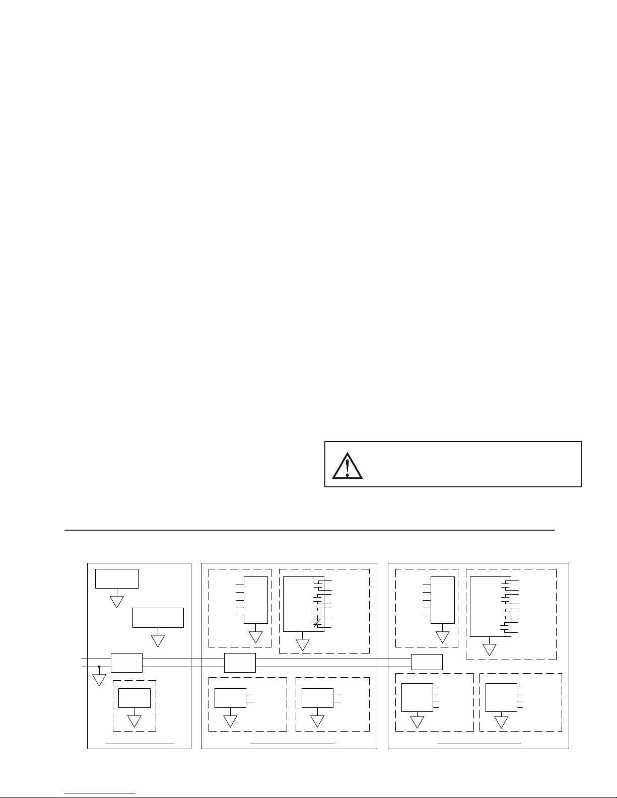
11. ALARMS:
PORT 3
ETHERNET
B
ISOLATED
A
POWER
SUPPLY
+
-
24VDC
CSMSTR - MASTER CSPID1 - PID MODULE
PORT 2
A
COMMUNICATIONS
A
PORT 1
PROGRAMMING
HCM
0-20mA
0-10V
RTD
TC
C
ISOLATED
POWER
SUPPLY
SSR
OUTPUTS
E
OP1-SSR1
OP2-SSR2
ISOLATED
F
LINEAR
OUTPUT
ISOLATED
0-10V
0-20mA
INPUTS
ISOLATED
RELAY
OUTPUTS
OP1-RELAY
OP2-RELAY
OP3-RELAY
D
POWER
SUPPLY
ISOLATED
I
SSR
OUTPUTS
CSPID2 - PID MODULE
OP4-SSR4
ISOLATED
J
OUTPUTS
TRIAC
ISOLATED
0-20mA
HCM
0-10V
RTD
TC
OP1-RELAY
OUTPUTS
G
INPUTS
RELAY
ISOLATED
OP2-RELAY
OP3-RELAY
OP4-RELAY
H
OP3-SSR3
OP2-SSR2
OP1-SSR1
OP4-TRIAC4
OP3-TRIAC3
OP2-TRIAC2
OP1-TRIAC1
Modes:
Manual
Absolute High Acting
Absolute Low Acting
Deviation High Acting
Deviation Low Acting
Inside Band Acting
Outside Band Acting
Reset Action: Programmable; automatic or latched
Standby Mode: Programmable; enable or disable
Hysteresis: Programmable
Sensor Fail Response: Upscale
12. ANALOG DC OUTPUT (optional, CSPID1 only):
Selectable/programmable for 0-10 VDC, 0-20 mA, or 4-20 mA
Resolution:
Voltage: 500 μV
Current: 1 μA
Accuracy:
0.1% of full scale (18 to 28 °C)
0.2% of full scale (0 to 50 °C)
Update Time: 0.0 to 60.0 sec
Compliance (for current output only): 500 max.
Minimum load (voltage output only): 10 K min.
Outputs are independently jumper selectable for either 10 V or 20 mA. The
output range may be field calibrated to yield approximate 10% overrange and
a small underrange (negative) signal.
13. HEATER CURRENT MONITOR INPUT (optional):
Type: 300 V max, 50 A max. Single phase, full wave monitoring of load
currents
Input: 100 mA max. input for use with external current transformers
Input Resistance: 5
Accuracy: ±3.0% full scale, 5 to 100% of range
Frequency: 50 to 400 Hz
Minimum output on time for break alarm: 350 msec
14. ENVIRONMENTAL CONDITIONS:
Operating Temperature Range: 0 to +50 °C
Storage Temperature Range: -40 to +85 °C
Operating and Storage Humidity: 85% max relative humidity, non-
condensing, from 0 to +50°C
Vibration According to IEC 68-2-6: Operational 10 to 150 Hz, 0.075 mm
amplitude in X, Y, Z direction 1 g.
Shock According to IEC 68-2-27: Operational 25 g (10 g relay), 11 msec in
3 directions.
Altitude: Up to 2000 meters
15. CERTIFICA TIONS AND COMPLIANCES:
SAFETY
Check each module’s specifications to determine system compliance.
UL Listed, File #E302106, UL508, CSA 22.2 No. 14-M05 and File #E179259,
UL61010-1, CAN/CSA-C22.2 No. 61010-1; and File #E317425, ANSI/ISA
12.12.01-2007, CSA 22.2 No. 213-M1987
LISTED by Und. Lab. Inc. to U.S. and Canadian safety standards
IEC 61010-1, EN 61010-1: Safety requirements for electrical equipment
for measurement, control, and laboratory use, Part 1.
ELECTROMAGNETIC COMPATIBILITY
Emissions and Immunity to EN 61326: 2006: Electrical Equipment for
Measurement, Control and Laboratory use.
Immunity to Industrial Locations:
Electrostatic discharge EN 61000-4-2 Criterion B
4kV contact discharge
Electromagnetic RF fields EN 61000-4-3 Criterion B
8kV air discharge
3
10V/m (80 MHz to 1 GHz)
3 V/m (1.4 GHz to 2 GHz)
1 V/m (2 GHz to 2.7 GHz)
Fast transients (burst) EN 61000-4-4 Criterion B
power 2kV
I/O signal 1kV
I/O signal connected to power 2kV
Surge EN 61000-4-5 Criterion B
power 1 kV L to L, 2 kV L to G
signal 1 kV
RF conducted interference EN 61000-4-6 Criterion A
3 Vrms
Emissions:
Emissions EN55011 Class A
Notes:
1. Criterion A: Normal operation within specified limits.
2. Criterion B: Temporary loss of performance from which the unit selfrecovers.
3. The module’s analog input and/or output signals may deviate during
disturbance but self-recover when disturbance is removed.
4. Power supplied from backplane via Master Module.
16. CONSTRUCTION: Case body is burgundy high impact plastic. For indoor
use only. Installation Category II, Pollution Degree 2.
17. CONNECTIONS: Removable wire clamp screw terminal blocks.
Wire Gage: 28-16 AWG terminal gage wire
Torque: 1.96-2.23 inch/lbs (0.22-0.25 N-m)
18. MOUNTING: Snaps on to standard DIN style top hat (T) profile mounting
rails according to EN50022 -35 x 7.5 and -35 x 15.
19. WEIGHT: CSPID1: 7 oz (198.4 g)
CSPID2: 7 oz (198.4 g)
WARNING - EXPLOSION HAZARD - DO NOT DISCONNECT
EQUIPMENT UNLESS POWER HAS BEEN SWITCHED OFF OR
AREA IS KNOWN TO BE NON-HAZARDOUS.
BLOCK DIAGRAM
3
 Loading...