

Page 1
MODEL MDMU - MINIATURE DISPLAY MODULE COUNTER/TIMER
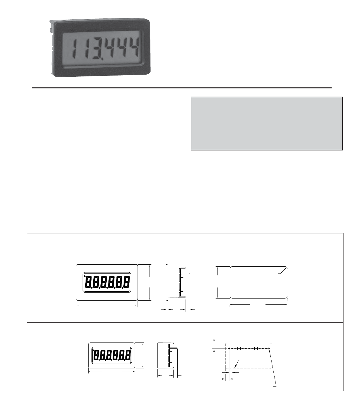
1.81 (46.0)
SEE
NOTE
0.06
(1.5)
1.06
(26.9)
0.2 (5.08) MAX.
0.14 (3.56) MIN.
1.68
-.02
+.03
0.93
-.02
+.03
(23.6 )
+.8
-.5
(42.7 )
+.8
-.5
(1.5)
R 0.06 MAX., 4PL.
NOTE: BACKLIGHT MODELS: 0.50" (12.7)
REFLECTIVE MODELS: 0.31" (8.0)
0.12 (3.1)
0.10 (2.5)
UNIT OUTLINE
THRU, 15 PL.
Ø 0.042 (1.07)
0.19 (4.8)
NOTE: BACKLIGHT MODELS: 0.56" (14.2)
REFLECTIVE MODELS: 0.37" (9.4)
1.65 (41.9)
0.90
(22.9)
SEE
NOTE
0.2 (5.08) MAX.
0.14 (3.56) MIN.
LCD, POSITIVE REFLECTIVE OR NEGATIVE TRANSMISSIVE
WITH YELLOW/GREEN OR RED BACKLIGHTING
COUNTER & TIMER ALL IN A SINGLE UNIT
COUNT POSITIVE OR NEGATIVE EDGE
9 RANGES IN TIMER MODE
SELECTABLE DECIMAL POINTS
5 VDC POWERED
PANEL MOUNT OR PC BOARD MOUNT
DESCRIPTION
The MDMU is a complete 6 digit Counter/Timer in a small panel or printed
circuit board mounted package. It is designed to operate from a 5 VDC power
supply. It has a 6 digit LCD, with 0.35" high digits, and 3 selectable decimal
points. In the timer modes, a flashing annunciator is supplied to indicate that the
signal input of the MDMU is active. The displays are available in positive image
reflective (black digits, reflective background) or negative image transmissive
(illuminated digits, dark background) with red or yellow/green backlighting.
The MDMU has four Mode Select and two Decimal Point Select inputs
This device contains CMOS circuitry which requires special anti-static
handling to the same degree required by standard CMOS integrated
circuits. Units should be stored in the conductive package used to ship the
device. Containers should be opened and units handled only on a
conductive table top by personnel wearing wrist-strap grounding equipment.
These devices have the same protection circuits as standard CMOS devices
to prevent damage to inputs due to nominal over-voltage.
CAUTION
available for determining the basic operation. In most applications, the MS and
DP inputs are hard wired to select the appropriate function (counter or timer)
and counter decimal point position.
The COUNTER mode is selected by setting the Mode select inputs to the
appropriate levels (Hardware selection). Decimal points may also be set using
the DP Inputs (Hardware selection).
The TIMER mode and range is selected by setting the Mode Select inputs to
the appropriate levels (Hardware selection). The timing range increments
available are
1 msec, 10 msec, 100 msec, 1 sec, 0.1 min, 1 min, 0.01 hr, 0.1 hr,
and 1 hr. The TIMER ACTIVE annunciator will flash at a 1 Hz rate when the
input to the timer is activated.
SPECIFICATIONS
1. DISPLAY: 6 Digit LCD, 0.35" (8.89 mm) high characters, available in
positive image reflective (black digits, reflective background) or negative
image transmissive (illuminated digits, dark background) with red or yellow/
green backlighting.
2. POWER REQUIREMENTS:
Reflective Versions: 5.0 VDC ±10% 100 μA max.
Backlight Versions: 5.0 VDC ±10% 25 mA max.
3. DECIMAL POINTS:
Timer: Determined by the timing mode selected.
Counter: 3 programmable positions.
DIMENSIONS Note: Recommended minimum clearance behind the panel for mounting clip installation is 2.25" (57.2)W x 1.5" (38.1)H
In inches (mm)
PANEL MOUNT UNIT PANEL CUT-OUT
PRINTED CIRCUIT BOARD MOUNT UNIT RECOMMENDED PCB LAYOUT
1
Page 2
4. ANNUNCIATOR: Flashes at a 1 Hz rate in the Timer mode when the signal
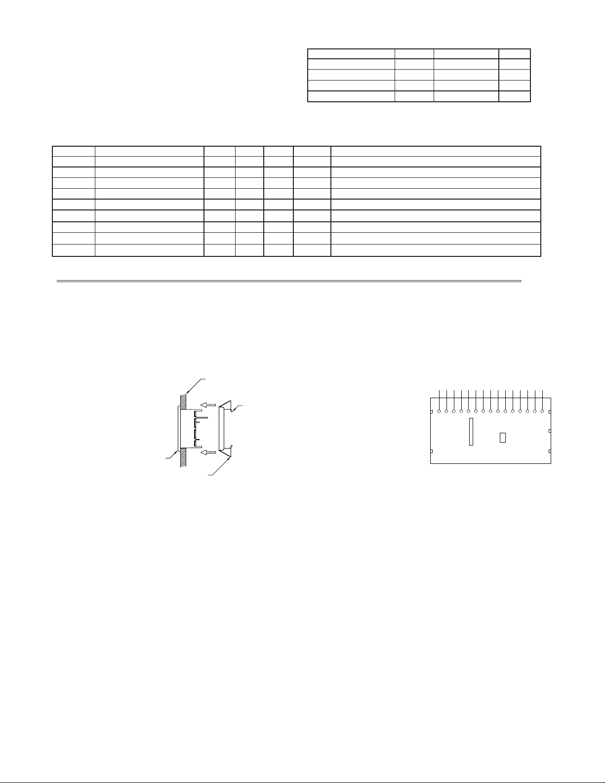
BEZEL
MOUNTING CLIP
EXISTING PANEL THICKNESS
0.031" to 0.125"
(0.79 to 3.18)
LOCKING
TAB
VSS (GND)
CNT
NO CONNECTION
NO CONNECTION
NO CONNECTION
LATCH
RST
MS1
MS2
MS3
MS4
NO CONNECTION
DP2
DP1
V
DD
input (CNT) is activated.
5. CONSTRUCTION: High impact black plastic case (mounting clip included
with panel mount models).
6 RELATIVE HUMIDITY: Less than 85% RH (non condensing)
7. WEIGHT:
Reflective Panel Mount: 0.275 oz (7.26 g)
Reflective PCB Mount: 0.26 oz (6.8 g)
MAXIMUM RATINGS
RATING SYMBOL VALUE UNITS
DC Supply Voltage VDD 5.5 VDC
Input Voltage, all inputs V
Operating Temperature T
Storage Temperature TSTG -40 to +85 °C
Transmissive Panel Mount: 0.38 oz (10.43 g)
Transmissive PCB Mount: 0.356 (9.75 g)
ELECTRICAL SPECIFICATIONS - VDD = 5.0 VDC = 10% @ 25 C unless otherwise specified.
SYMBOL PARAMETER MIN TYP MAX UNITS NOTES
VDD Supply Voltage 4.5 5.0 5.5 VDC Voltages outside these parameters may cause display problems
DD Supply Current - Transmissive 20 25 mA VDD = 5.0 VDC - 10 KHz Counting Rate.
I
IDD Supply Current - Reflective 50 100 AVDD = 5.0 VDC - 10 KHz Counting Rate.
IH Valid High Voltage 3.0 VDC
V
IL Valid Low Voltage 1.5 VDC
V
IN Input Leakage Current 0.1 1.0
I
Fc Count Frequency - CNT 9.9 KHz 50% Duty cycle
R,L RST, LATCH Pulse Width 30
T
CCTB Time Base Accuracy 0.025
A
A
sec
IN -0.5 to (VDD +0.5) VDC
A -35 to +85 °C
INSTALLATION
The MDMUs are available in either a panel mount or printed circuit board
mount design. The panel mount units are provided with a mounting clip to
securely hold the unit in the panel cutout.
Panel Mount Installation:
1. Cut panel opening to specified
dimensions. Remove burrs
and clean the panel opening.
2. Install MDMU through the
panel cutout as shown in
Figure 1.
3. Slide mounting clip over rear
of unit until clip is against the
back of panel. The unit has
slots for the locking tabs to
hold it in the panel opening.
Note: Hold the MDMU front
bezel in place when sliding the
mounting clip in to position
PCB Mount Installation:
1. Prepare printed circuit board hole pattern to the specifications.
2. Unit should be hand soldered using good soldering techniques and hand
cleaned if necessary.
Figure 1
WIRING CONNECTIONS
The electrical connections are
made via terminal pins located on
the back of the unit. The terminal
pins are on 0.100" center lines and
can be mated with the RLC Model
HWK7 cable assembly or many
standard 0.100" center line
connectors. When wiring the unit,
refer to Figure 2 to identify the
wire position with the proper
function.
There are certain considerations
that should be observed when
running the signal wires. A length
of wire can act like an antenna,
and the closer it is to a source of
electrical noise, the more it
becomes susceptible to that noise.
These are a few rules that should be followed when running these wires.
1. Never run signal wires in the same conduit or raceway with A.C. power lines,
conductors feeding motors, solenoids, SCR controls, heaters, etc.
2. Signal wires within enclosures should be routed as far away as possible from
contactors, control relays, transformers, and other noisy components.
3. When shielded wire is used, connect the shield to the common of the MDMU
unit, and leave the other end of the shield disconnected and insulated from
machine ground.
4. Connect common of the MDMU to machine ground at one point only.
Figure 2
2
Page 3

PIN DESCRIPTIONS
VSS (GND)
CNT
NO CONNECTION
NO CONNECTION
NO CONNECTION
LATCH
RST
MS1
MS2
MS3
MS4
NO CONNECTION
DP2
DP1
V
DD
RST
.0022 µf
220K
GND
+5 V
GND +5 V
0.15 (3.8)
12 (305)
CIRCUIT #1; BROWN
0.100 (2.54), TYP.
STRIPPED AND TINNED
COLOR CODED RIBBON CABLE
0.100 (2.54), TYP.
(All inputs are Schmidt trigger inputs)
: +5 VDC power
V
DD
V
: GND or common supply terminal
SS
DP1 & DP2: Counters - See Decimal Point Configuration Chart
Timers - Tie low
MS1-MS4: See Mode Select Inputs Chart
RST: Active low, will reset the display to zero
LATCH: Counters - A HIGH level will freeze the display, a LOW level will
allow the counter to update the display normally
Timers - Tie low
CNT: Counters - This is the count input (edge trigger determined by mode)
Timers - This is the run input (active low = timer runs)
DECIMAL POINT CONFIGURATION CHART
DP2 DP1 DISPLAY
000
0 1 0.0
1 0 0.00
1 1 0.000
TYPICAL APPLICATIONS
COUNTER - TTL signal input counting. Positive edge
incrementing (leading edge).
MODE SELECT INPUTS CHART
MODE MS4 MS3 MS2 MS1 MODE OF OPERATION
0 00000.001 Second Timer
1 00010.01 Second Timer
2 00100.1 Second Timer
3 00111 Second Timer
4 01000.1 Minute Timer
5 01011 Minute Timer
6 01100.01 Hour Timer
7 01110.1 Hour Timer
8 10001 Hour Timer
9 1001DO NOT USE
10 1010Negative Edge Counter
11 1011Positive Edge Counter
12 1100DO NOT USE
13 1101DO NOT USE
14 1110DO NOT USE
15 1111DO NOT USE
1 MINUTE TIMER - With Leading Zero Blanking
enabled. Time starts with the switch closed. Time
stops and holds the display with the switch open.
ACCESSORY: MDM CABLE ASSEMBLY - HWK70000
TTL SIGNAL
TIMER
RUN
VSS (GND)
CNT
NO CONNECTION
NO CONNECTION
NO CONNECTION
LATCH
RST
MS1
MS2
MS3
MS4
DP2
DP1
DD
V
RST
.0022 µf
220K
220K
ORDERING INFORMATION
MODEL NO DESCRIPTION PART NUMBER
Panel Mount W/Reflective Display MDMU0000
Panel Mount W/Yel-Grn Backlighting MDMU0010
MDMU
HWK7 MDM Cable Assembly HWK70000
3
Panel Mount W/Red Backlighting MDMU0020
PC Board Mount W/Reflective Display MDMU0100
PC Board Mount W/Yel-Grn Backlighting MDMU0110
PC Board Mount W/Red Backlighting MDMU0120
Page 4

The Company warrants the products it manufactures against defects in materials and workmanship
LIMITED WARRANTY
for a period limited to two years from the date of shipment, provided the products have been stored,
handled, installed, and used under proper conditions. The Company’s liability under this limited
warranty shall extend only to the repair or replacement of a defective product, at The Company’s
option. The Company disclaims all liability for any affirmation, promise or representation with
respect to the products.
The customer agrees to hold Red Lion Controls harmless from, defend, and indemnify RLC
against damages, claims, and expenses arising out of subsequent sales of RLC products or products
containing components manufactured by RLC and based upon personal injuries, deaths, property
damage, lost profits, and other matters which Buyer, its employees, or sub-contractors are or may be
to any extent liable, including without limitation penalties imposed by the Consumer Product Safety
Act (P.L. 92-573) and liability imposed upon any person pursuant to the Magnuson-Moss Warranty
Act (P.L. 93-637), as now in effect or as amended hereafter.
No warranties expressed or implied are created with respect to The Company’s products except
those expressly contained herein. The Customer acknowledges the disclaimers and limitations
contained herein and relies on no other warranties or affirmations.
 Loading...