

Page 1
Tel +1 (717) 767-6511
Fax +1 (717) 764-0839
www.redlion.net
MOTOR DRIVE CONTROLLER
MASTER AND FOLLOWER MODES OF OPERATION
PROGRAMMABLE SETPOINTS:
TWO SPEED (Master)
TWO RAMP RATE (Master)
TWO RATIO (Follower)
TWO RATIO RAMP RATE (Follower)
ONE JOG SPEED
ONE JOG RAMP RATE
8 CHARACTER BY 2 LINE ALPHANUMERIC DISPLAY
FOUR PROGRAMMABLE INDICATION DISPLAYS
Bulletin No. MDC-D
Drawing No. LP0306
Released 04/14
ON LINE SETPOINT INCREMENT/DECREMENT
SELECTABLE DISPLAY SCROLLING
ABILITY TO LIMIT OPERATOR ACCESS TO PROGRAMMING
PARAMETERS
ENGLISH PROGRAMMING MENUS
FREQUENCY INPUTS ARE SWITCH SELECTABLE FOR A
VARIETY OF SOURCES
PROGRAMMABLE CONTROL INPUTS
THREE SOLID STATE OUTPUTS
VARIABLE SPAN (5 TO 15 VDC) ISOLATED DRIVE OUTPUT
FEEDBACK LOSS DETECTION
PROGRAMMABLE ALARM TYPES
INTERNAL OR EXTERNAL DRIVE OUTPUT REFERENCE
DIAGNOSTICS MODE
115/230VAC SWITCH SELECTABLE
NON-VOLATILE MEMORY
NEMA 4X/IP65 SEALED FRONT PANEL BEZEL
DESCRIPTION
The Motor Drive Controller (MDC) regulates motor speed by varying an
isolated DC control signal to a motor drive system. There are two modes of
operation, Master and Follower.
Master Mode provides control of a motor directly via programmed speed
setpoints in the MDC. Regulation is maintained by a feedback frequency to the
MDC taken from the motor shaft or a downstream shaft pulse encoder. Follower
Mode controls a motor’s speed as a ratio to a second motor’s speed or outside
frequency source. Ratio setpoints are programmed into the MDC causing the
motor to “follow” the lead motor or frequency at a fixed speed ratio.
Master Mode has two speed setpoints and two ramp setpoints. Follower
Mode has two ratio setpoints and two ramp setpoints. Both modes share a jog
speed setpoint and a jog ramp setpoint. All setpoints are retained in non-volatile
memory when the unit is powered down.
The Motor Drive Controller has the added feature of allowing real time
adjustment of the Speed (Master Mode) or Ratio (Follower Mode) setpoint
while the unit is operating a motor drive system. The setpoint may be adjusted
via the front panel keypad using the “Up” or “Down” arrow keys, or via 2 User
Inputs programmed for increment setpoint and decrement setpoint.
User flexibility is provided through the two-line by eight-character
alphanumeric display. The display features English language menus for easy
viewing and simplified programming. The four scroll-through indication
displays can be programmed to show various parameters and to automatically
scroll, if desired. A program disable DIP switch used with an external User Input
can be utilized to protect the settings and guarantee that no unwanted changes
occur during operation.
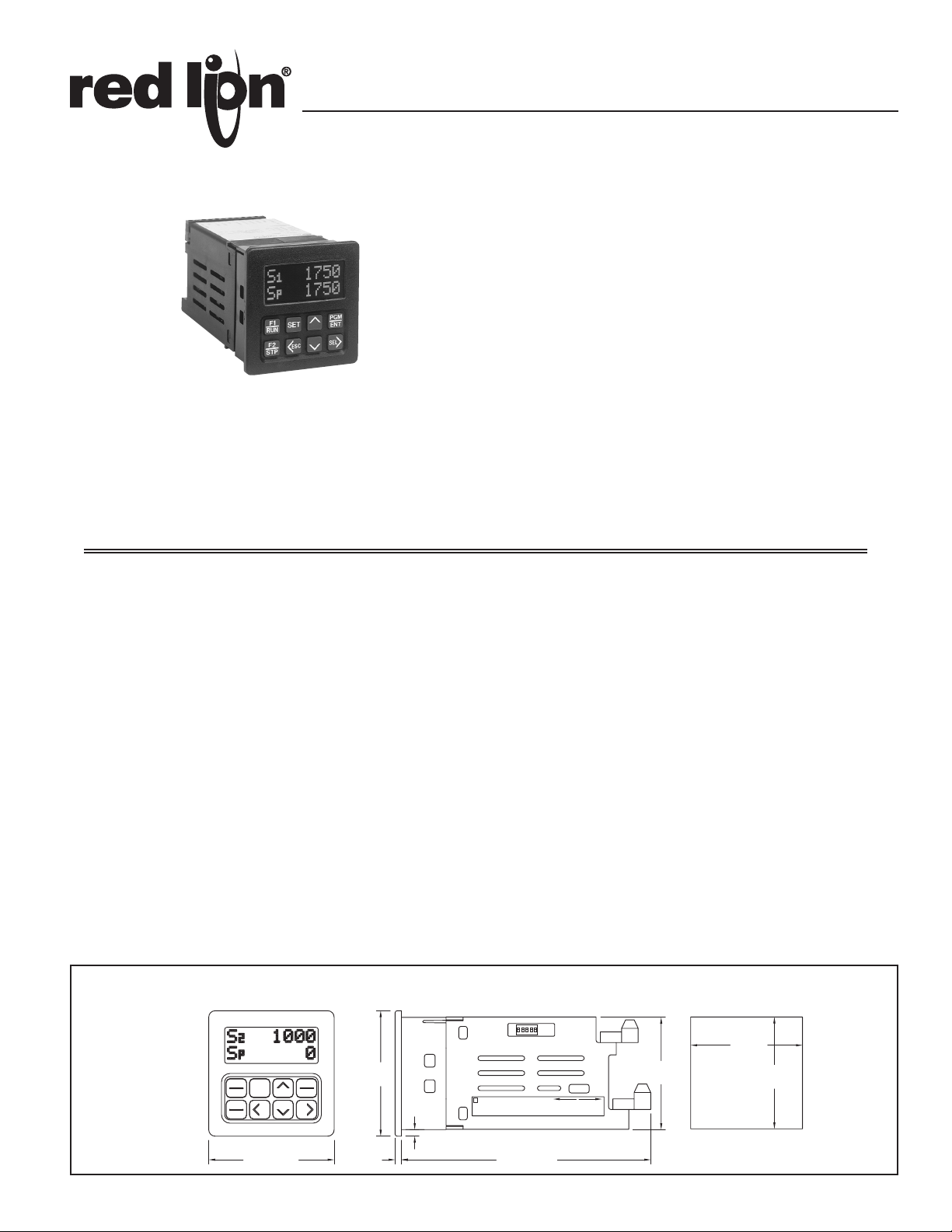
DIMENSIONS In inches (mm)
Note: Recommended minimum clearance (behind the panel) for
mounting clip installation is 3.0" (76.2) H x 4.0" (101.6) W.
There are five dedicated control inputs on the MDC:
RUN
RAMP STOP
FAST STOP
JOG
OPEN LOOP
There are six programmable control inputs: two front panel function keys and
four remote user inputs. The F1 and F2 keys are factory programmed for RUN
and R-STOP respectively. This eliminates the need for external switches in
some applications.
There are three solid state outputs, two are programmable alarms and one is
a dedicated Drive Enable output. Programmable alarm functions include:
High Alarm
Low Alarm
Deviation Alarm
Zero Speed
Disabled
These may be programmed for boundary or latching operation, high or low
acting.
Changing speed setpoints and programming information is easily
accomplished by scrolling through menus and selecting the correct parameter.
There are three main modules or menu loops:
Display Module
User Setpoint Module
Programming Module
Scaling is accomplished by entering the desired values for feedback pulses
per revolution (PPR), the maximum RPM, and the maximum display value.
PANEL CUT-OUT
2.95
F1
RUN
F2
STP
2.95 (74.9) 5.87 (149.1)
PGM
SET
ENT
SELESC
(74.9)
.15
(3.8)
.155 (3.8)
E
CAUTION:
SELECT PROPER VOLTAGE
BEFORE APPLYING POWER
1
115 VAC230 VAC
50/60 HZ, 10 VA
+.03
2.68
-.01
+.8
(68 )
2.64
(67.1)
LB01269
-.3
2.68
(68)
Page 2
DESCRIPTION (Cont’d)
The unit is factory configured for an isolated 0 to 10 VDC drive output
signal. The output drive signal can be adjusted to span from 0 to 15 VDC via an
accessible potentiometer. The drive output is jumper selectable for an external
reference. To use the external reference, the MDC is connected to the drive in
place of an external potentiometer.
The Motor Drive Controller has a light weight, high impact plastic case with a
clear viewing window. The sealed front panel meets NEMA 4X/IP65 specifications
for wash-down and/or dusty environments, when properly installed. Plug-in style
terminal blocks simplify installation and wiring change-outs.
SAFETY SUMMARY
All safety related regulations, local codes and instructions that appear in the
manual or on equipment must be observed to ensure personal safety and to
prevent damage to either the instrument or equipment connected to it. If
equipment is used in a manner not specified by the manufacturer, the protection
provided by the equipment may be impaired.
Do not use this unit to directly command motors, valves, or other actuators
not equipped with safeguards. To do so, can be potentially harmful to persons
or equipment in the event of a fault to the unit.
CAUTION: Risk of Danger.
Read complete instructions prior to
installation and operation of the unit.
CAUTION: Risk of electric shock.
SPECIFICATIONS:
1. DISPLAY: 2x8, 0.3" (7 mm) high characters, negative image transmissive
LCD, with red LED backlighting.
2. POWER: 115/230 VAC ±10%, 50/60 Hz, 10 VA, switch selectable.
3. MEMORY: Non-volatile E2PROM retains all programming information and
values when power is removed or interrupted.
Power Cycles(ON/OFF): 100,000 min.
Data Retention: 10 years min.
4. SENSOR POWER: +12 VDC ±25% @ 100 mA.
5. INPUTS (LEAD AND FEEDBACK): DIP Switch selectable to accept input
pulses from a variety of sources including outputs from CMOS or TTL
circuits and all standard RLC sensors.
Input Freq:
1 Hz to 20 KHz (Master Mode), 1 Hz to 12 KHz (Follower Mode).
Logic: Input trigger levels VIL= 1.5 V
Current Sinking: Internal 7.8 KΩ pull-up to +12 VDC, I
Current Sourcing: Internal 3.9 KΩ pull-down, 7.3 mA @ 28 VDC
Magnetic Pickup:
Sensitivity: 200 mV PEAK.
Hysteresis: 100 mV.
Input impedance: 3.9 KΩ @ 60 Hz.
Maximum input voltage: ±50 V PEAK.
Note: For magnetic pickup input, the Sink/Source DIP switch must be in the
SRC position.
6. CONTROL LOOP RESPONSE: 10 msec (Master Mode), 20 msec
(Follower Mode).
7. CONTROL ACCURACY:
0.01% of Speed Setpoint (Master Mode)
0.02% of Ratio Setpoint (Follower Mode)
Minimum Frequency Resolution: 0.00125 Hz
8. ERROR TRIM: ±4095 BITS.
9. ERROR GAIN: 0 to 99%.
10. RAMP RATE: (Ramp 1, Ramp 2, and Jog Ramp)
1 Hz to 20 KHz/sec, set in user units/sec.
0.0001 to 1.9999 ratio units/sec (Ramp 1 & 2 in Follower Mode).
11. CONTROL INPUTS:
Internal 10 KΩ pull-up to +5 VDC. VIL = 1.0 V
Response time = 10 msec nominal, 30 msec max.
INPUTS SWITCH CONNECTIONS
RUN Momentary N.O.
FAST STOP Momentary N.C.
RAMP STOP Momentary N.C.
JOG Sustained N.O.
OPEN LOOP Maintained
USER INPUTS(4) Function Specific
12. OUTPUTS:
Drive Enable, Alarm 1, and Alarm 2:
Solid state, current sinking NPN Open collector transistor.
VCE = 1.1 V
(Internal zener diode protection.)
@ 100 mA max., V
SAT
; V
MAX
= 3.75 V
IH
MAX
= 30 VDC max.
OH
.
MIN
MAX
, VIH = 4.0 V
= 1.6 mA.
MAX
.
MIN
.
Response Time:
Drive Enable: 10 msec nominal; 30 msec max.
Alarm 1&2: Programmable
Normal: 1 sec nominal, 2 sec max.
Fast: 20 msec nominal, 40 msec max.
Isolated Drive Output: Jumper selectable internal/external reference 5 mA max.
Internal Reference: Pot adjustable from 0 to 5 VDC min. through 0 to 15
VDC max. span.
External Reference: 15 VDC max. (positive polarity only).
Isolation: 2300 Vrms for 1 minute
250 V working
13. ENVIRONMENTAL CONDITIONS:
Operating Temperature: 0 to 50°C
Storage Temperature: -40 to 70°C
Operating and Storage Humidity: 85% max. RH (non-condensing) from
0°C to 50°C.
Altitude: Up to 2000 meters
14. CONSTRUCTION: High impact plastic case with clear viewing window.
The front panel meets NEMA4 X/IP65 requirements for indoor use when
properly installed. Installation Category II, Pollution Degree 2. Panel gasket
and mounting clips included.
15. WEIGHT: 1.5 lbs. (0.68 Kg).
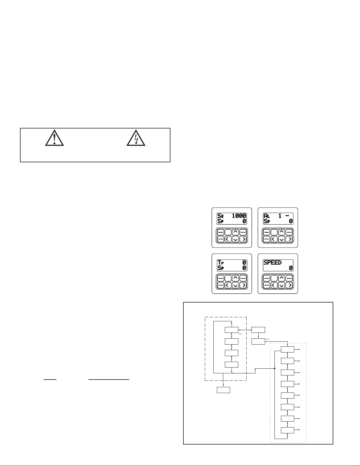
PROGRAMMING
Programming the MDC unit is accomplished through the front panel keypad,
which allows the user to enter into Main Menus, Sub-Menus, and Edit Menus.
The English language prompts, the flashing parameter values, and the front panel
keypad aid the operator during programming. In the normal run mode, the main
display loop allows the user to scroll through the four programmable indication
displays, using the direction keys. From the main loop, setpoints, alarm values
and a gain value may be accessed directly for changes, without entering the
programming loop. All other parameters are accessed through the pro-gramming
loop, which can be set to require an access code number for loop entry. In the
programming loop, parameters can be viewed or changed and the operator can
exit anywhere in the loop.
F1
RUN
F2
STP
F1
RUN
F2
STP
INDICATION DISPLAY
MODULE
SET
USER
SETPOINTS
*** - ACTIVE ONLY WHEN THE PROGRAM
DISABLE FUNCTION IS ENABLED.
1-4 - THE FOUR INDICATION DISPLAYS
--DASHED LINE:
MAIN DISPLAY LOOP
... DOTTED LINE:
PROGRAMMING LOOP
SET
ESC SEL
SET
SPEED
1
>
S R
1 1
p
S
2
AL
- -
p 500
S
3
Tr
Sp
4
>>>
PGM
ENT
PGM
ENT
SELESC
>
ESC
<
500
PGM
>
ENT
RUN
500
>>>
102
500
PROGRAM
MODE
PRO.CODE
***
0000
F1
RUN
F2
STP
F1
RUN
F2
STP
SEL
>
PGM
ENT
0
ESC
<
PGM
SET
ENT
ESCSEL
PGM
SET
ENT
ESCSEL
PROGRAMMING
MODULE
>
MASTER
MODE
PROGRAM
SCALING
> >
PROGRAM
USER
>>>>>>
PROGRAM
ALARMS
PROGRAM
DISPLAY
PROGRAM
OPTIONS
PROGRAM
DIAGNOST
PROGRAM
SECURITY
>>>>>>>>
SEL
>
SEL
>
SEL
>
SEL
>
SEL
>
SEL
>
SEL
>
SEL
>
2
Page 3

PROGRAMMABLE FUNCTIONS
MODES
Master
Follower
SCALING
Pulses per Revolution Feedback (PPR FB) ranges from 1 to 59999
Maximum RPM Feedback (MAX RPM FB) ranges from 1 to 59999
Display Decimal Point (DSP DP) ranges from 0 to 0.00000
Maximum Display Units (DSP UNIT) ranges from 1 to 99999
*Pulses per Revolution Lead (PPR LD) ranges from 1 to 59999
*Maximum RPM Lead (MAX RPM LD) ranges from 1 to 59999
*These parameters are available in Follower Mode only.
Note: Values may be programmed in the range listed, provided that the
maximum equivalent frequency does not exceed 20971 Hz. If this occurs,
“OVFLW” will flash and a new entry will be required.
SETPOINTS
2 SPEED (Master Mode) - ranges from 0 to 99999 (or Display Unit Max.).
2 RAMP RATE (Master Mode) - ranges from 1 to 99999.
2 RATIO (Follower Mode) - ranges from 0.0000 to 1.9999.
2 RAMP RATE (Follower Mode) - ranges from 0.0001 to 1.9999 ratio units.
1 JOG SPEED - ranges from 0 to 99999 (or Display Unit Maximum).
1 JOG RAMP RATE - ranges from 1 to 99999.
2 ALARM - ranges from 0 to 99999.
1 GAIN - ranges from 0 to 99.
Note: Values may be programmed in the ranges listed, provided that the
maximum equivalent frequency does not exceed 20,971 Hz ( 20 KHz/sec for
Ramp Rate). If this occurs, a message will flash and the maximum is
automatically entered by the unit.
USER INPUTS
There are four programmable external user inputs and two programmable
front panel function keys. The options for each user input are the same, except
for the two function keys (F1/RUN & F2/STP), which have additional options.
No Mode:
If a user input terminal or a function key is activated, it will be ignored.
View Display 1-4:
Causes the selected indication display (1, 2, 3, or 4) to be displayed and held
from anywhere in the main display loop.
Change Display:
Causes the indication display to toggle to the next indication display.
Reset Alarm(s) Output:
Places the alarm(s) output(s) in its inactive state.
Setpoint Select/Toggle:
Selects Setpoint 1 or Setpoint 2 for the active speed (or ratio) setpoint. This
is a maintained select action for User Inputs 1 to 4, and a momentary toggle
action for F1 or F2.
Ramp Select/Toggle:
Selects Ramp 1 or Ramp 2 for the active acceleration and deceleration ramp
rate. This is a maintained select action for User Inputs 1 to 4, and a
momentary toggle action for F1 or F2.
Ramp Override:
Overrides the acceleration/deceleration ramp routine causing the unit to jump
to the ramp endpoint.
Setpoint Increment:
Only an external User Input can be used for this option. The currently active
speed or ratio setpoint is incremented when the User Input is made active. If
the input remains active for more than 5 display unit increments, the scroll
rate will progressively increase.
Setpoint Decrement:
Only an external User Input can be used for this option. The currently active
speed or ratio setpoint is decremented when the User Input is made active. If
the input remains active for more than 5 display unit increments, the scroll
rate will progressively increase.
Program Disable:
Only an external user input can be used for this option. When used with the
program disable DIP switch, this option can limit operator access to
programmable parameters.
Run (F1 only):
Pressing the F1 button causes the MDC to accelerate the motor from Stop
mode to the active speed setpoint using the active ramp rate.
R-Stop(F1 or F2 only):
Pressing the function key programmed for R-Stop causes the unit to
decelerate the motor from its active speed to Stop mode using the active ramp
rate.
F-Stop(F1 or F2 only):
Pressing the function key programmed for F-Stop causes the unit to execute
a fast stop, taking the motor from its current speed immediately to the stop
mode. The deceleration is limited only by the motor and drive.
Jog(F1 or F2 only):
This function is only available from the Stop mode. Pressing and holding the
function key programmed for Jog causes the unit to accelerate the motor to
the jog speed setpoint using the jog ramp rate.
ALARMS
Type Of Alarm:
High Alarm: Alarm output activates when the feedback input is greater than
or equal to the alarm value.
Low Alarm: Alarm output activates when the feedback input is less than or
equal to the alarm value.
Deviation Alarm: The alarm output activates when the feedback input is
outside a ± band.
Zero Speed Alarm: Alarm output activates when the feedback input receives
no input pulse for at least one second.
Disabled: The alarm output is inactive when disabled.
Phase:
Each output can have its active logic state set for Positive phase (ON) or
Negative phase (OFF).
Latched Or Boundary:
An alarm programmed for a latched output stays active until it is manually
reset by a User Input. An alarm programmed for boundary output stays active
as long as the alarm condition exists, after which the output returns to its
inactive state.
Fast Or Normal Update:
The normal update rate for the alarm outputs is once each second. The fast
update rate occurs at an interval less than or equal to 40 msec.
INDICATION DISPLAYS
If an indication display is to show two different numeric values, one for each
line, there will be a single or dual character mnemonic to the left of the numeric
value. Each line of each indication display can be programmed to show
mnemonics or a numeric value. The following list shows the single or dual
character mnemonics that will be displayed when value is selected and the
mnemonics for each programmable option.
VAL MNE DESCRIPTION
S1 99999 SETPT. 1 Speed or ratio setpoint 1
S2 99999 SETPT. 2 Speed or ratio setpoint 2
Sp 99999 SPEED Actual speed in user display units (feedback)
R 1.999 RATIO Actual ratio (follower mode)
%D 100.0 % DEV. % deviation of actual speed from target speed
%O 100.0 % OUTPUT Analog drive output- % of full scale voltage
FB 20971 FB. FREQ Feedback frequency in pulses/sec (Hz.)
LD 12000 LD. FREQ Lead frequency in pulses/sec (Hz.)
A1 99999 ALARM 1 Alarm 1 setpoint
A2 99999 ALARM 2 Alarm 2 setpoint
Tr 4095 TRIM Error correction in bits (-4095 to +4095)
STATUS DISPLAYS
Operating Status:
Setpoint 1, ramp rate 1, Stop mode
Alarm Output Status:
Alarm 1 active, alarm 2 inactive
Operating Status:
The operating status display indicates the currently active speed or ratio
setpoint (S1 or S2), the currently active ramp rate (R1 or R2), and the mode
of operation (RUN, STP, or JOG). An arrow will replace the “R” for the
currently active ramp rate indication when an actual ramp up or down is in
progress.
Alarm Status:
The alarm status display indicates that an alarm output is active when the
corresponding output number (1 or 2) is displayed. When an alarm output is
inactive, a dash is displayed.
3
Page 4

OPERATOR ACCESS
This is used with the program disable DIP switch or an external user input
that is selected for the program disable function. When a setpoint is selected as
NO, it can be viewed, but NOT changed from the front panel keypad. The
following setpoint values can be disabled from front panel access programming:
Speed/Ratio Setpoint 1 and 2 Jog Speed
Ramp Rate 1 and 2 Jog Ramp
Alarm Setpoint 1 and 2 Gain
Setpoint Scroll Menu
USER SETTINGS
The operator can reset ALL parameters to the factory settings if desired.
PROGRAM DIAGNOSTICS
This allows testing of the various MDC inputs and outputs. It is especially
useful after unit installation to independently test the operation of external
switches, relays, the feedback transducer, and the motor drive system.
Inputs - The MDC displays an alphanumeric character to indicate a Dedicated
Function Input or a User Input is active. This allows the user to check switch
operation and wiring connections to the Inputs.
Alarm Outputs - The up and down arrow keys are used to select an alarm
output and set it to the active or inactive state. This allows the user to check
the operation of devices wired to the alarm outputs and the wiring
connections.
Drive Output - This function allows the user to test the Drive System. A %
Output value is entered through the front panel keypad causing the motor to
run at the corresponding open loop speed. The display indicates the motor’s
feedback frequency.
PROGRAM SECURITY
The programmable code number is used in conjunction with the program
disable DIP switch and/or a user input programmed for the program disable
function to limit operator access to programming.
FOLLOWER MODE APPLICATION
A fertilizer production facility is mixing pellets containing Nitrogen with
pellets that contain Phosphorus. A chemical ratio of 1:1 is determined by the
speed of two different conveyors. Because of differences in the gearing of
the conveyor and concentration of the pellets, the Nitrogen conveyor motor
must run at 3 times the speed of the Phosphorus conveyor motor in order to
produce a 1:1 mixture. The maximum speed of both motors is 2000 RPM.
Set the follower MDC scaling to produce a 1:1 mixture of Nitrogen and
Phosphorus when a setpoint of 1.0000 is entered. Display speed units are in
RPM’s. Both the lead and feedback frequency are taken from 60 tooth gears
on each motor shaft.
1) Choose the Phosphorus conveyor motor for the follower MDC. It runs
slower than the Nitrogen conveyor motor.
2) Set the Pulses per revolution feedback to 60.
3) Set the MAX RPM feedback to 2000. This is the conveyor motor’s
maximum operating speed.
4) Set display decimal point to 0.
5) Set display unit to 2000. The display speed unit maximum is 2000 at a
MAX RPM FB of 2000. If the display units wanted were conveyor feet/
minute or Phosphorus pellets in lbs/sec, the equivalent display value for
2000 RPM would be entered.
6) Set the pulses per revolution lead to 60.
7) Setting the MAX RPM Lead:
This is the Lead RPM that would be necessary to have a 1:1 mixture if
the Follower Speed was MAX RPM FB (2000 RPM). Since the Nitrogen
conveyor motor must run 3 times as fast as the Phosphorus motor, MAX
RPM LD = 3 * 2000 = 6000 RPM. Set MAX RPM LD = 6000 RPM. This
is the correct value, even though the Nitrogen conveyor motor would never
actually run at 6000 RPM. A ratio setpoint of 1.0000 on the MDC is now
equal to a 1:1 mixture of Phosphorus and Nitrogen.
LEAD INP
WHITE
FEEDBACK INP
COMM.
(SEE SIDE
AC PWR
USR.INP. 1
4321 12111098765
LABEL)
RED
USR.INP. 2
+12VDC OUT
USR.INP. 3
COMM.
BLACK
USR.INP. 4
AL-1 SNK
RUN
AL-2 SNK
R-STOP
DRIVE ENABLE OUT
OPEN LOOP
JOG
F-STOP
ISOLATED
DRIVE
OUTPUT
-+REF.
COMM.
10 1167894321 5
MOTOR
DRIVE
EMERGENCY
STOP
STOP
MOTOR
START
MOTOR
MASTER MODE APPLICATION
A pump delivers a maximum of 30.0 gallons per minute with a shaft speed of
1750 RPM. A shaft pulse encoder generates 60 pulses/revolution. Set the MDC
scaling to control and display pumping speed in tenths of a gallon/minute. In the
Program Scaling Module:
1) Set the pulses per revolution feedback to 60.
2) Set the maximum RPM feedback to 1750. This is the pump shaft’s maximum
operating speed.
3) Set display decimal point to 0.0. Display units are in 0.1 gpm.
4) Set max display units to 30.0. The display speed unit maximum is 30.0 at a MAX
RPM FB of 1750.
MOTOR
ORDERING INFORMATION
MODEL NO. DESCRIPTION
MDC Motor Drive Controller with Red Backlighting MDC00100
4
PART NUMBERS
115/230VAC
 Loading...