

MODEL LPAX- 6 DIGIT LARGE PAX DISPLAY FOR DIGITAL INPUTS
LARGE LED DISPLAY READABLE TO 70 FEET
VARIOUS DIGITAL INPUT MODULES;
COUNT AND RATE INPUT
CLOCK/TIMER
SERIAL SLAVE
ALARMS, ANALOG OUTPUT, AND COMMUNICATION
PROGRAMMABLE USER INPUTS
PROGRAMMABLE FUNCTION KEYS
UNIVERSAL AC/DC POWERED MODELS
PC SOFTWARE FOR METER CONFIGURATION
U
R
C
US LISTED
L
IND. CONT. EQ.
51EB
NEMA 4/IP65
Bulletin No. LPAX6-E
Drawing No. LP0530
Released 05/13
GENERAL DESCRIPTION
The LPAX Display is a versatile display that can increase productivity by
offering the plant floor or production area a large visual display of their current
status. Whether your measurement is rate, count, or time, the LPAX can satisfy
your requirement. These LPAX displays accept various digital inputs through
the use of input modules (MPAX) which allow the unit to adapt to most any
application. The MPAX Modules offer the same features as our highly
successful PAX Series Panel Meters. Additional plug-in option cards can add
alarms, analog output, and communication/bus capabilities, making the LPAX a
truly Intelligent Panel Meter.
SAFETY SUMMARY
All safety regulations, local codes and instructions that appear in this and
corresponding literature, or on equipment, must be observed to ensure personal
safety and to prevent damage to either the instrument or equipment connected
to it. If equipment is used in a manner not specified by the manufacturer, the
protection provided by the equipment may be impaired.
The protective conductor terminal is bonded to conductive
parts of the equipment for safety purposes and must be
connected to an external protective earthing system.
CAUTION: Risk of Danger.
Read complete instructions prior to
installation and operation of the unit.
CAUTION: Risk of electric shock.
SPECIFICATIONS
Additional specifications, wiring, programming, and information for the
individual MPAX models are contained in the corresponding standard PAX
literature. This PAX literature is shipped with the ordered MPAX model.
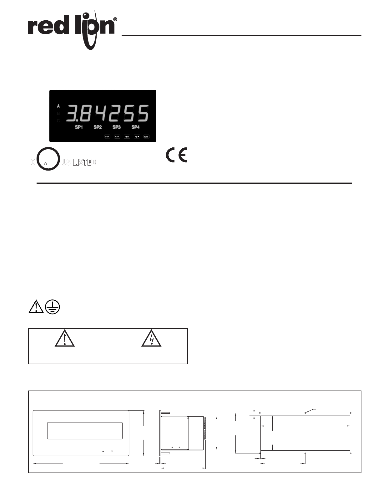
1. DISPLAY: 1.5" (38 mm) Red LED
6-Digit (LPAX0600): (-99999 to 999999)
6-Digit (LPAXCK00): (0 to 999999)
2. POWER REQUIREMENTS:
AC Modules: 85 to 250 VAC, 50/60 Hz, 18 VA
DC Modules: 11 to 36 VDC or 24 VAC ±10%, 50/60 Hz, 14 W
3. INPUT: Accepts digital input modules, see “Selecting Your Display
Components and Option Cards.”
4. ANNUNCIATORS:
LPAX0600: A, B, C, SP1, SP2, SP3, and SP4
LPAXCK00: TMR, CNT, DAT, SP1, SP2, SP3, and SP4
5. KEYPAD: Five tactile membrane switches integrated into the front panel
6. CERTIFICATIONS AND COMPLIANCES:
SAFETY
UL Recognized Component, File #E179259, UL61010A-1, CSA 22.2 No. 1010-1
Recognized to US and Canadian requirements under the Component
Recognition Program of Underwriters Laboratories, Inc.
UL Listed, File # E137808, UL508, CSA C22.2 No. 14-M95
LISTED by Und. Lab. Inc. to U.S and Canadian safety standards
Type 4 Enclosure rating (Face Only), UL50
IECEE CB Scheme Test Certificate # US/8843/UL
CB Scheme Test Report # 04ME11209-20041018
Issued by Underwriters Laboratories, Inc.
IEC 61010-1, EN 61010-1: Safety requirements for electrical equipment
for measurement, control, and laboratory use, Part 1.
IP65 Enclosure rating (Face only), IEC 529
ELECTROMAGNETIC COMPATIBILITY
EMC specifications determined by the MPAX module.
DIMENSIONS In inches (mm)
A
A
B
C
123456
SP1 SP2 SP3 SP4
SP1 SP2 SP3 SP4
DSP PAR RST
10.00 (254.0)
F2
F1
4.75
(120.7)
.120
(3.05)
4.65 (118.1)
PANEL CUT-OUT
.234 (5.94) DIA.
THRU, TYP.
+.04
-.00
4.20
3.54
(106.7)
(89.9)
1
.285
(7.2)
.08 (2.0)
+.03
-.00
3.63
+.76
-.00
(92.2 )
2X
4.725 (120.0)
9.29
+1.01
-.00
(236.0 )
7. ENVIRONMENTAL CONDITIONS:
Operating Temperature Range: Determined by the MPAX module
Storage Temperature Range: -40 to 60°C
Operating and Storage Humidity: 0 to 85% max. RH (non-condensing)
Altitude: Up to 2000 meters
8. MOUNTING REQUIREMENTS:
Max. panel thickness is 0.375" (9.5 mm)
Min. panel thickness for NEMA 4/IP65 sealing is 0.060" (1.57 mm)
9. MODULE INSTALLATION:
24-pin shrouded connector on LPAX engages connector on MPAX module
upon installation. Shroud ensures proper alignment by providing a lead-in for
the module connector.
10. CONNECTIONS: All wiring connections are made to the MPAX module
via high compression cage-clamp terminal blocks. Wiring instructions are
provided with the MPAX module.
CAUTION: DISCONNECT ALL POWER BEFORE
INSTALLING OR REMOVING MODULE
11. CONSTRUCTION: Steel front panel, enclosure, and rear cover with
textured black polyurethane paint for scratch and corrosion resistance
protection. Sealed front panel meets NEMA 4/IP65 specifications for indoor
use when properly installed. Installation Category II, Pollution Degree 2.
Panel gasket and keps nuts included.
12. WEIGHT: 2.7 lbs (1.2 kg) (less module)
About the MPAX Input Modules
The MPAX Module serves as the input to the LPAX Display. There are several different modules to cover a variety of inputs. The MPAX module provides input
scaling which allows the LPAX to display most any engineering unit. Once the MPAX is inserted into the LPAX, the unit has the same functions and capabilities of
our PAX Series Intelligent Panel Meters. A full set of PAX programming instructions will be included with the MPAX module.
Note: The MPAX provides the operating power for the LPAX, therefore you must select either the AC or DC MPAX corresponding with your application and available
power.
Selecting Your Display Components and Option Cards
To build a complete display unit, you will need an LPAX and an MPAX Input Module. The LPAX is only a display and will not operate without an MPAX module.
Please use the following chart to identify the appropriate MPAX module (including supply power) and LPAX Display that will satisfy your application.
SIGNAL TYPE
Count/Rate/Serial Slave MPAXI020 MPAXI030 -YESYESYESLPAX0600
Count MPAXC020 MPAXC030 ---YESLPAX0600
Rate MPAXR020 MPAXR030 ---YESLPAX0600
Clock/Timer
Timer
MPAX MODULES*
85-250 VAC 11 to 36 VDC / 24 VAC
MPAXCK00
MPAXTM00
MPAXCK10
MPAXTM10
*For detailed module and plug-in card specifications, see corresponding PAX literature. (i.e. For MPAXI specifications, see the PAXI literature)
**The LPAXCK will only operate with the Clock/Timer MPAX input module.
OPTIONAL PLUG-IN CARDS AND ACCESSORIES
WARNING: Disconnect all power to the unit before
installing Plug-in cards.
Adding Option Cards
The MPAX series meters can be fitted with up to three optional plug-in cards.
However, only one card from each function type can be installed at a time. The
function types include Setpoint Alarms (PAXCDS), Communications
(PAXCDC), and Analog Output (PAXCDL). The cards can be installed initially
or at a later date. Each optional plug-in card is shipped with installation and
programming instructions.
COMMUNICATION CARDS (PAXCDC)
A variety of communication protocols are available for the PAX and MPAX
series. Only one of these cards can be installed at a time. When programming
the unit via Crimson (for MPAXI) or SFPAX (for MPAXCK or MPAXTM), the
RS232 or RS485 Cards must be used.
PAXCDC10 - RS485 Serial (Terminal) PAXCDC30 - DeviceNet
PAXCDC1C - RS485 Serial (Connector) PAXCDC40 - Modbus (Terminal)
PAXCDC20 - RS232 Serial (Terminal) PAXCDC4C - Modbus (Connector)
PAXCDC2C - RS232 Serial (Connector) PAXCDC50 - Profibus-DP
SETPOINT CARDS (PAXCDS)
The MPAX series has four setpoint alarm output plug-in cards. Only one of
these cards can be installed at a time. (Logic state of the outputs can be reversed
in the programming.) These plug-in cards include:
Dual relay, FORM-C, Normally open & closed
Quad relay, FORM-A, Normally open only
Isolated quad sinking NPN open collector
Isolated quad sourcing PNP open collector
LPAX
DISPLAYS
LPAXCK00**
LPAXCK00**
OPTIONAL PLUG-IN CARD COMPATABILITY
SETPOINT
YES
YES
YES
YES
ANALOGCOMMS
-
-
REAL-TIME
CLOCK
YES
-
LINEAR DC OUTPUT (PAXCDL)
Either a 0(4)-20 mA or 0-10 V retransmitted linear DC output is available
from the analog output plug-in card. The programmable output low and high
scaling can be based on the input, max, min, or total display value. Reverse
slope output is possible by reversing the scaling point positions.
PAXCDL10 - Retransmitted Analog Output Card
PROGRAMMING SOFTWARE
CRIMSON - MPAXI Only
Crimson is a Windows® based program that allows configuration of the
LPAX meter from a PC. Crimson offers standard drop-down menu commands,
that make it easy to program the LPAX meter. The LPAX program can then be
saved in a PC file for future use. A PAX serial plug-in card is required to
program the meter using the software.
SFPAX - MPAXCK and MPAXTM Only
The SFPAX is a Windows® based program that allows configuration of the
LPAX meter from a PC. Using the SFPAX makes it easier to program the LPAX
meter and allows saving the PAX program in a PC file for future use. On-line
help is available within the software. A PAX serial plug-in card is required to
program the meter using the software.
2
1.0 ASSEMBLING THE DISPLAY
CAUTION:
123
45
6
7
8
9
10
11
DISCONNECT ALL
POWER BEFORE INSTALLING OR
REMOVING MODULE
SLOT
TWIST
!
WHILE FIRMLY DEPRESSING REAR FINGER TABS (TOP & BOTTOM),
INSERT SCREWDRIVER BLADE (3/16" OR 1/4") INTO NARROW SLOT
(AT THE ARROW) AND TWIST IN THE DIRECTION SHOWN.
TO REMOVE MODULE:
MODEL LPAX
RED LION CONTROLS
YORK, PA. MADE IN U.S.A.
PAXCDC10
RS485 COMMUNICATION
12
13
14
15
- B(-)
- A(+)
- COMM
- N/C
1 2 3 4 5 6
7
8 9 10 11
~ ~
AC AC
85-250VAC
50/60Hz
14VA
COMMUNICATION OPTION ANALOG OUT OPTION
SETPOINT (SP) OPTION
MODEL PAXD
RED LION CONTROLS
YORK, PA. MADE IN U.S.A.
SEE LITERATURE FOR
JUMPER SELECTION
SIGNAL INPUTS
USER INPUTS
VOLT/OHM
CURRENT
+EXCITATION
COMM
1
2
3
N/C
COMM
!
R
-19
17
+18
-
+16
ANALOG OUTPUT
PAXCDL10
RLY3
25
21
RLY2
22
COMM
RLY1
20
QUAD RELAY S.P.
PAXCDS20
0-10V
ANALOG
OUTPUT
OUTPUT
ANALOG
0-20mA
24
23
COMM
RLY4
RELAYS RATED
3A @ 250VAC
(RESISTIVE LOAD)
MODULE
CONNECTOR
MODULE
REAR COVER
CAUTION
LABEL
MODULE
RETENTION
LATCH (TOP
AND BOTTOM)
OPTION CARD(S)
INSTALLED ON THIS SIDE
MPAX MAIN
CIRCUIT BOARD
(BOTTOM SIDE)
TERMINAL #1
MODULE AND
OPTION CARD(S) LABELS
(APPLY TO REAR COVER PLATE)
CAUTION
DISCONNECT
ALL POWER
BEFORE
OPENING
LPAX DISPLAY
REAR VIEW
METAL PANEL
MUST BE
CONNECTED TO
!
E
MA2204X
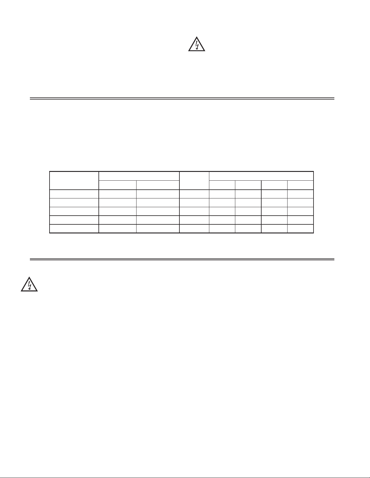
CAUTION: The MPAX main circuit board and the option cards
contain static sensitive components. Before handling the module
or the cards, discharge static charges from your body by
touching a grounded bare metal object. Handle the module by
the rear plastic cover only, and the option cards by the board
edges. Dirt, oil or other contaminants that contact the circuit
boards or components can adversely affect circuit operation.
Prior to installing the LPAX Display, it is recommended that the MPAX and
any option cards be assembled first. This will allow you the opportunity to
insure all the boards are fitted properly into their connectors.
Installing the Option Cards
If your application requires option cards, they
should be installed into the MPAX before it is
installed into the LPAX Display. Refer to
the literature enclosed with the option
cards for installation instruction.
Installing the MPAX
To install the MPAX Module, align
the module with the opening in the
LPAX case, as illustrated. The module
must be oriented as shown, with
terminal #1 toward the top of the
LPAX case. Carefully slide the module
into the LPAX case. The LPAX and
MPAX connectors will begin to engage
about ¼" from the bottom. At this
point, apply a small amount of pressure to
the rear of the MPAX module to fully engage
the connection. Be sure the module fully snaps into
the slots at the rear of the LPAX case. The display is
ready for installation.
Figure 1, Installing an MPAX Module and Option Cards
WARNING: Exposed line voltage exists on the MPAX main circuit
board and the option cards. DO NOT apply power to the
module OR load circuits until the module is properly installed
in the LPAX case.
NOTE: All module and option card labels must be installed as
shown for safety purposes.
Installing the Labels
Each option card and the MPAX are shipped with a connection label. These
labels must be applied to the rear of the LPAX in the positions shown in the
drawing.
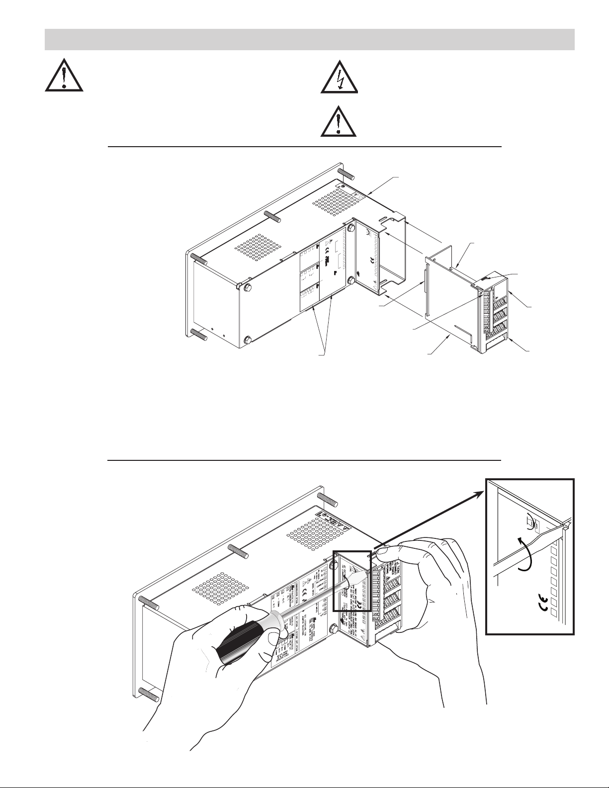
Removing The MPAX Module
To remove the MPAX Module from the LPAX Display, first
remove all power and load circuits. Then insert a flat
screwdriver blade (3/16" or 1/4") into the narrow slot between
the LPAX rear cover plate and the module’s plastic cover
as illustrated in Figure 2. Twist the screwdriver in
the direction shown to disengage the internal
connectors while firmly squeezing and
pulling back on the rear finger tabs
(top and bottom). Carefully
slide the module out of the
LPAX case, keeping it
properly aligned with the
case opening.
Figure 2, Removing an MPAX Module
3
TWIST
SLOT
7 654 32
8

2.0 INSTALLING THE DISPLAY
CAUTION:
1234567891011
DISCONNECT ALL
POWER BEFORE INSTALLING OR
REMOVING MODULE
SLOT
TWIST
!
WHILE FIRMLY DEPRESSING REAR FINGER TABS (TOP & BOTTOM),
INSERT SCREWDRIVER BLADE (3/16" OR 1/4") INTO NARROW SLOT
(AT THE ARROW) AND TWEIST IN THE DIRECTION SHOWN.
TO REMOVE MODULE:
MODEL LPAX
RED LION CONTROLS
YORK, PA. MADE IN U.S.A.
PAXCDC10
RS485 COMMUNICATION
12
13
14
15
- B(-)
- A(+)
- COMM
- N/C
1 2 3 4
5 6
7 8 9 10
11
~~
AC AC
85-250VAC
50/60Hz
14VA
COMMUNICATION OPTION ANALOG OUT OPTION SETPOINT (SP) OPTION
MODEL PAXD
RED LION CONTROLS
YORK, PA. MADE IN U.S.A.
SEE LITERATURE FOR
JUMPER SELECTION
SIGNAL INPUTS
USER INPUTS
VOLT/OHM
CURRENT
+EXCITATION
COMM
1
2
3
N/C
COMM
!
R
-19
17
+18
-
+16
ANALOG OUTPUT
PAXCDL10
RLY3
25
21
RLY2
22
COMM
RLY1
20
QUAD RELAY S.P.
PAXCDS20
0-10V
ANALOG
OUTPUT
OUTPUT
ANALOG
0-20mA
24
23
COMM
RLY4
RELAYS RATED
3A @ 250VAC
(RESISTIVE LOAD)
MODULE
RETENTION
LATCH (TOP
AND BOTTOM)
MOUNTING
PANEL
PANEL
GASKET
FRONT
PANEL
MODULE RELEASE
FINGER TAB
(TOP & BOTTOM)
CASE
VENT
HOLES
REAR COVER PLATE
CAUTION
DISCONNECT
ALL POWER
BEFORE
OPENING
CONNECTED TO
MUST BE
METAL PANEL
MA2204X
E
!
CONNECT THIS STUD
TO A PROTECTIVE
EARTHING SYSTEM
MOUNTING STUDS AND NUTS
(6 PLACES)
LPAX DISPLAY INSTALLATION
The LPAX display is intended to be mounted into a panel or enclosure. The display is
provided with a gasket to provide a water-tight seal. The recommended minimum panel
thickness for NEMA 4/IP65 sealing is 0.060" (1.57 mm).
For panel mounting, prepare the panel cut-out to the dimensions
shown. The supplied template may be used to mark the cut-out
and hole locations on the panel. After the panel cut-out has been
deburred, slide the panel gasket over the rear of the display and
onto the mounting studs. Insert the display into the panel
cut-out as illustrated in Figure 3. Install six # 10-32 keps
nuts (supplied) and tighten evenly for uniform gasket
compression. Do not over-tighten the nuts.
By using additional mounting accessories, the LPAX
can be surface-wall mounted, suspended, or bottom mounted.
Separate installation instructions are provided with the
mounting accessories.
Environment And Cleaning
The display should be installed in a location that does not
exceed the maximum operating temperature and provides good
air circulation. Placing the system near devices that generate
excessive heat should be avoided.
The bezel should be cleaned only with a soft cloth and neutral
soap product. Do NOT use solvents. Continuous exposure to
direct sunlight may accelerate the aging process of the bezel.
Figure 3, Installing The LPAX Into A Panel
3.0 WIRING AND PROGRAMMING THE DISPLAY
Once assembled, the LPAX and MPAX have all the same functions and
capabilities of our PAX Series Intelligent Panel Meters. Therefore, you will find
the appropriate PAX information packed with the MPAX Module. Simply
follow the instructions to wire and program the display for your application.
TROUBLESHOOTING
For technical assistance, contact technical support.
ORDERING INFORMATION
TYPE MODEL NO. DESCRIPTION PART NUMBERS
Display LPAX
Digital
Input
MPAX
Module
PAXCDS
Optional
Plug-In
Cards
PAXCDC*
PAXCDL*
PAXUSB*
PAXRTC*
SFCRD**
ENC9
Accessories
*Refer to “Selecting Your Display Components and Option Cards.”
**Available as a FREE download from the Red Lion website. www.redlion.net
SHR
MB
6-Digit Display for Digital MPAX Modules LPAX0600
6-Digit Display for MPAXCK (Clock/Timer) and MPAXTM Only LPAXCK00
Count/Rate Indicator Module, AC Powered MPAXI020
Count/Rate Indicator Module, DC/24 VAC Powered MPAXI030
Count Indicator Module, AC Powered MPAXC020
Count Indicator Module, DC/24 VAC Powered MPAXC030
Rate Indicator Module, AC Powered MPAXR020
Rate Indicator Module, DC/24 VAC Powered MPAXR030
Clock/Timer Module, AC Powered MPAXCK00
Clock/Timer Module, DC/24 VAC Powered MPAXCK10
Timer Module, AC Powered MPAXTM00
Timer Module, DC/24 VAC Powered MPAXTM10
Dual Setpoint Relay Output Card PAXCDS10
Quad Setpoint Relay Output Card PAXCDS20
Quad Setpoint Sinking Open Collector Output Card PAXCDS30
Quad Setpoint Sourcing Open Collector Output Card PAXCDS40
RS485 Serial Communications Output Card with Terminal Block PAXCDC10
Extended RS485 Serial Communications Output Card with Dual RJ11 Connector PAXCDC1C
RS232 Serial Communications Output Card with Terminal Block PAXCDC20
Extended RS232 Serial Communications Output Card with 9 Pin D Connector PAXCDC2C
DeviceNet Communications Card PAXCDC30
Modbus Communications Card PAXCDC40
Extended Modbus Communications Card with Dual RJ11 Connector PAXCDC4C
Profibus-DP Communications Card PAXCDC50
Analog Output Card PAXCDL10
PAX USB Programming Card (Not included in PAX product UL E179259 file). PAXUSB00
Real Time Clock Card for MPAXCK (Clock/Timer) Only PAXRTC00
Crimson 2 PC Configuration Software for Windows 98, ME, 2000 and XP (for MPAXI) SFCRD200
NEMA 4 Enclosure for LPAX ENC90000
Shroud for LPAX SHRLPAX0
Mounting Bracket for LPAX MBLPAX00
 Loading...