

red lion G3HSPA Product Manual
Bulletin No. G3HSPA-B
LED
Drawing No. LP0965
Released 04/15
Tel +1 (717) 767-6511
Fax +1 (717) 764-0839
www.redlion.net
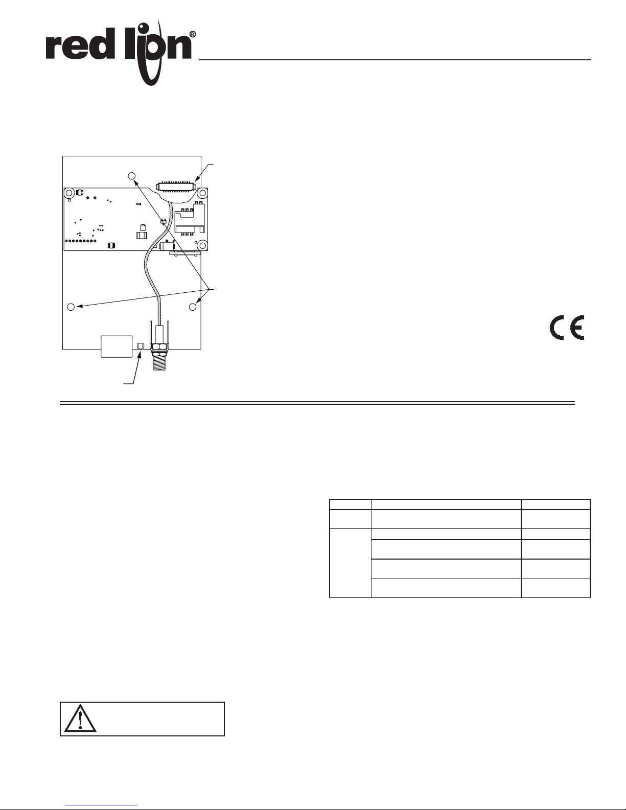
MODEL G3HSPA - G3 SERIES HSPA+ CELLULAR MODEM
OPTION CARD FOR G3 OPERATOR INTERFACE TERMINALS
CONNECTOR
(SIDE 2)
MOUNTING HOLES
(3 PLACES)
POWER
ANTENNA
GENERAL DESCRIPTION
The G3HSPA option card allows the user to add HSPA+ cellular modem
capability to their G3 operator interface terminal. The cellular standard adopted
in this option card is HSPA+ with fallback capability to 3G and 2G. It can get
speeds up to 21 Mbps downlink and 5.76 Mbps uplink. It’s built upon the GSM
standard, offered in the US and widely available throughout the world. HSPA+
can be used for services such as Wireless Application Protocol (WAP) access,
Short Message Service (SMS), and for Internet connectivity.
The G3HSPA option card is penta-band, allowing it to work in frequencies
across the Americas, Europe and Asia. US and Canada work in the 850/1900
MHz bands, while Europe, Middle East, Africa and most of Asia work in the
900/1700/2100 MHz HSPA+ frequencies.
The G3HSPA requires the addition of a SIM (Subscriber Identity Module)
card, which is inserted into the holder prior to installation of the G3HSPA card.
The SIM card securely stores the service-subscriber key (IMSI) used to identify
a subscriber, and is used to connect to the network to obtain an IP address from
the provider.
SAFETY SUMMARY
All safety related regulations, local codes and instructions that appear in the
manual or on equipment must be observed to ensure personal safety and to
prevent damage to either the instrument or equipment connected to it. If
equipment is used in a manner not specified by the manufacturer, the protection
provided by the equipment may be impaired.
Do not use the module to directly command motors, valves, or other actuators
not equipped with safeguards. To do so can be potentially harmful to persons or
equipment in the event of a fault to the module.
CAUTION: Risk of Danger.
Read complete instructions prior to
installation and operation of the unit.
z CONFIGURED USING CRIMSON SOFTWARE (VERSION 3.0 OR
LATER)
z SUPPORTS HSPA+ CELLULAR DATA CONNECTIVITY WITH FALL
BACK TO 3G AND 2G
z UP TO 21 MBPS DOWNLINK/5.76 MBPS UPLINK SPEEDS
z INSTALLS INSIDE A G3 OPERATOR INTERFACE TERMINAL
z INSTALLATION AND CONNECTION HARDWARE INCLUDED
WITH CARD
CONTENTS OF PACKAGE
- G3HSPA Option card
- Cable already attached to G3HSPA option card
- Hardware pack consisting of three screws.
- This hardware bulletin
ORDERING INFORMATION
MODEL NO. DESCRIPTION PART NUMBER
G3HSPA
1
Antenna is NOT included with the card. Must be purchased separately if
GSM/HSPA+ Modem Option Card for G3
operator interface
2G/3G 3" hinged antenna ANT-TG090113
2G/3G/4G LTE low profile direct permanent
mount antenna, IP67 rated
ANT
2G/3G 4.5" whip magnetic mount antenna,
IP65 rated
2G/3G low profile direct permanent mount
antenna, IP65 rated
needed.
1
G3HSPA00
ANT-G30B108111
ANT-GA107201111
ANT-G21B301111
SPECIFICATIONS
1. POWER REQUIREMENTS:
24VDC ± 20%; (independent from the host G3 power connection). Must use
NEC Class 2 or Limited Power Source (LPS) rated power supply.
G3HSPA Max Power:
HSPA+ Mode: During continuous active webserver traffic
Instantaneous maximum: 5.5 W
Average: 3.7 W
GPRS Mode:
Instantaneous maximum: 14.5 W (1.1 msec every 4.6 msec)
Average: 7.0 W
2. LINK STATUS LEDs:
Link Status - Link Status LED shows cellular link condition.
1
3. COMMUNICATIONS:
LED
Isolation from G3HSPA Antenna connector to G3 operator interface:
500 VDC for 1 minute.
4. ENVIRONMENTAL CONDITIONS:
Operating Temperature Range: 0 to 50 °C
Storage Temperature Range: -20 to 80 °C
Operating and Storage Humidity: 80% maximum relative humidity (non-
condensing) from 0 to 50 °C.
Altitude: Up to 2000 meters.
5. ANTENNA CONNECTOR:
SMA Female connector requires:
50 Ohm antenna with SMA male connector
Penta-band HSPA+ antenna (850/900/1700/1900/2100 MHz) for global
support.
Dual-band (850/1900 MHz) antenna for US and Canada only
Dual band (900/2100 MHz) for Europe only
Voltage Standing Wave Ratio (VSWR) should not exceed 2.0:1
The antenna cable should be 50Ω impedance, RG178/U or RG174/U type and
be able to connect to the RSMA (Male) jack bulkhead. The antenna could be
horizontal, vertical or right angled. Longer antenna cable would equate to
signal loss.
6. CERTIFICATIONS AND COMPLIANCES:
SAFETY:
IEC 61010-1, EN 61010-1: Safety requirements for electrical equipment for
measurement, control and laboratory use, Part 1.
ELECTROMAGNETIC COMPATIBILITY
Emissions and Immunity to EN 61326: Electrical Equipment for Measurement,
Control and Laboratory use.
Immunity to Industrial Locations: Reference G3 unit for immunity
specifications
Emissions:
Emissions EN 55011 Class A
Note:
1. G303 unit’s emission level changes from Class B to Class A levels when
G3HSPA option card is installed.
2. The G3HSPA option card has been tested and found to comply with the
limits for a Class A digital device, pursuant to part 15 of the FCC rules.
7. CONSTRUCTION: Installation Category I, Pollution Degree 2.
8. INSTALLATION REQUIREMENTS: Card must be installed inside the
rear cover of a G3 operator interface with the hardware provided. See
“Installing the G3HSPA Option Card” for more details.
9. WEIGHT: 2.5 oz (70.9 g)
InstallIng the g3hsPa OPtIOn Card
INSTALLATION INSTRUCTIONS
Caution: The option and main circuit boards contain static
sensitive components. Before handling the cards, discharge
static charges from your body by touching a grounded bare
metal object. Ideally, handle the cards at a static controlled clean
workstation. Also, handle the cards by the edges only. Dirt, oil,
or other contaminants that may contact the card can adversely
affect circuit operation.
Warning: Depending upon the G3 operator interface, high voltage
may be present inside the operator interface. Be sure to remove
all power before removing the rear cover of the operator interface.
Each G3HSPA option card comes with a cable for communications from the
main G3 operator interface PC board. It also comes with three screws for
attaching the option card to the inside of the G3 operator interface’s rear cover.
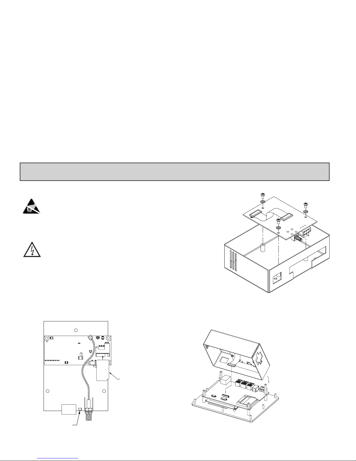
The first step is to buy a SIM Card from one of the GSM/HSPA+ providers
and insert into the option card SIM Card slot. The SIM Card slot is the
rectangular slot on top of the HSPA Cellular Modem in G3HSPA option card as
shown in Figure 1. See SIM Card details in the Software/Unit Operation section
for more details.
TOP SIDE
AM
HSPA CELL MODEM
To install the option card remove all
power and communication cables from
the unit. The chassis ground
connection to the rear cover may
be left connected. The G3
operator interface literature
contains instructions for
removing the rear cover, refer
to the “Battery & Time
Keeping” section.
Using the three
screws provided,
connect the option
card to the rear cover
as shown in Figure 2.
V2 HMIs connect at
the main board.
Figure 2
Connect the cable from the option card to CN11 on the main board of the G3
operator interface as shown in Figure 3. Be sure both ends of the cables are
firmly seated into their appropriate connector housing.
G3HSPA00
OPTION CARD
POWER
ANTENNA
Figure 1
SIM CARD
ORIENTATION
Figure 3
2
 Loading...