

Page 1
Bulletin No. G3GSM-B
Drawing No. LP0775
Released 10/10
Tel +1 (717) 767-6511
Fax +1 (717) 764-0839
www.redlion.net
MODEL G3GSM - GSM/GPRS CELLULAR MODEM OPTION CARD FOR G3
OPERATOR INTERFACE TERMINALS
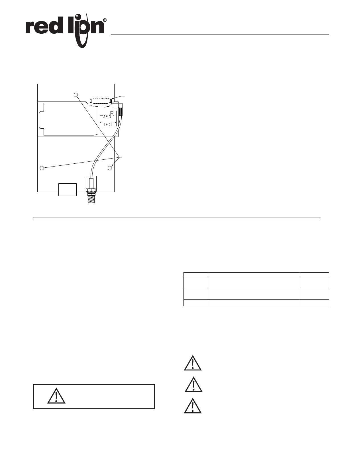
CONNECTOR
(SIDE 2)
CONFIGURED USING CRIMSON ® 2.0 SOFTWARE
INSTALLS INSIDE A G3 OPERATOR INTERFACE TERMINAL
INSTALLATION AND CONNECTION HARDWARE INCLUDED
WITH CARD
MOUNTING HOLES
(3 PLACES)
POWER
ANTENNA
GENERAL DESCRIPTION
The G3GSM option card allows the user to add GSM/GPRS cellular modem
capability to their G3 operator interface terminal. GSM/GPRS is the most
prevalent cellular technology in today's markets. GPRS can be used for services
such as Wireless Application Protocol (WAP) access, Short Message Service
(SMS), and for Internet communication services such as email and World Wide
Web access. The G3GSM modem option card is quad-band, allowing it to work
in frequencies across Americas, Europe and Asia. US and Canada work in the
850/1900 MHz bands, while Europe, Middle East, Africa and most of Asia work
in the 900/1800 MHz GSM/GPRS frequencies.
The G3GSM requires the addition of a SIM (Subscriber Identity Module)
card, which is inserted into the holder prior to installation of the G3GSM card.
The SIM card securely stores the service-subscriber key (IMSI) used to identify
a subscriber, and is used to connect to the network to obtain an IP address from
the provider.
SAFETY SUMMARY
All safety related regulations, local codes and instructions that appear in the
literature or on equipment must be observed to ensure personal safety and to
prevent damage to either the instrument or equipment connected to it. If
equipment is used in a manner not specified by the manufacturer, the protection
provided by the equipment may be impaired.
Do not use the controller to directly command motors, valves, or other
actuators not equipped with safeguards. To do so can be potentially harmful to
persons or equipment in the event of a fault to the controller.
CONTENTS OF PACKAGE
- G3GSM Option Card
- Cable already attached to G3GSM option card
- Hardware pack consisting of three screws.
- This hardware bulletin
ORDERING INFORMATION
MODEL NO. DESCRIPTION PART NUMBER
G3GSM
ANT
SFCRM2 Crimson 2.0
1
Antenna is NOT included with the card. Must be purchased separately if
needed.
2
Contact your Red Lion distributor or visit www.redlion.net/g3 for complete
selection of accessories.
3
Use this part number to purchase Crimson on CD with a printed manual,
USB cable, and RS-232 cable. Otherwise, the software can be downloaded
from www.redlion.net/g3.
GSM/GPRS Modem Option Card for G3 operator
1
interface
Quad-band, 6 inch, direct mount GSM/GPRS
cellular antenna
THIS EQUIPMENT IS SUITABLE FOR USE IN CLASS I,
DIVISION 2, GROUPS A, B, C, D, HAZARDOUS LOCATIONS,
OR NON-HAZARDOUS LOCATIONS ONLY
2
3
G3GSM000
G3QANT00
SFCRM200
CAUTION: Risk of Danger.
Read complete instructions prior to
installation and operation of the unit.
WARNING - EXPLOSION HAZARD - DO NOT DISCONNECT
EQUIPMENT WHILE THE CIRCUIT IS LIVE OR UNLESS THE AREA
IS KNOWN TO BE FREE OF IGNITABLE CONCENTRATIONS.
WARNING - EXPLOSION HAZARD - SUBSTITUTION OF ANY
COMPONENT MAY IMPAIR SUITABILITY FOR CLASS I,
DIVISION 2
1
Page 2
SPECIFICATIONS
1. POWER REQUIREMENTS:
24VDC ± 20%; 0.25A max; 0.25A typical (independent from the host G3
power connection). Must use NEC Class 2 or Limited Power Source (LPS)
rated power supply.
2. ENVIRONMENTAL CONDITIONS:
Operating Temperature Range: 0 to 50 °C
Storage Temperature Range: -20 to 80 °C
Operating and Storage Humidity: 80% maximum relative humidity (non-
condensing) from 0 to 50 °C.
Altitude: Up to 2000 meters.
3. ANTENNA CONNECTOR:
SMA Female connector requires:
50 Ohm antenna with SMA male connector
Quad-band antenna (850/900/1800/1900 MHz) for global support.
Dual-band (850/1900 MHz) antenna for US and Canada only
Dual band (900/1800 MHz) for Europe only
The antenna cable should be 50 impedance, RG178/U or RG174/U type
and be able to connect to the RSMA (Male) jack bulkhead. The antenna could
be horizontal, vertical or right angled. Longer antenna cable would equate to
signal loss.
4. CERTIFICA TIONS AND COMPLIANCES:
SAFETY:
IEC 61010-1, EN 61010-1: Safety requirements for electrical equipment for
measurement, control and laboratory use, Part 1.
ELECTROMAGNETIC COMPATIBILITY
Emissions and Immunity to EN 61326: Electrical Equipment for Measurement,
Control and Laboratory use.
Immunity to Industrial Locations: Reference G3 unit for immunity
specifications
Emissions:
Emissions EN 55011 Class A
Note:
1. G303 unit’s emission level changes from Class B to Class A levels when
G3GSM option card is installed.
2. The G3GSM option card has been tested and found to comply with the
limits for a Class A digital device, pursuant to part 15 of the FCC rules.
5. CONSTRUCTION: Installation Category I, Pollution Degree 2.
6. INSTALLATION REQUIREMENTS: Card must be installed inside the
rear cover of a G3 operator interface with the hardware provided. See
“Installing the G3GSM Option Card” for more details.
7. WEIGHT: 3.0 oz (85.41g)
INSTALLING THE G3GSM OPTION CARD
INSTALLATION INSTRUCTIONS
Caution: The option and main circuit boards contain static
sensitive components. Before handling the cards, discharge
static charges from your body by touching a grounded bare
metal object. Ideally, handle the cards at a static controlled clean
workstation. Also, handle the cards by the edges only. Dirt, oil,
or other contaminants that may contact the cards can adversely
affect circuit operation.
Warning: Depending upon the G3 operator interface, high voltage
may be present inside the operator interface. Be sure to remove
all power before removing the rear cover of the operator interface.
Each G3GSM option card comes with a cable for communications from the
main G3 operator interface PC board. It also comes with three screws for
attaching the option card to the inside of the G3 operator interface's rear cover.
The first step is to buy a SIM Card from one of the GSM/GPRS providers and
insert into the option card SIM Card slot. The SIM Card slot is the rectangular
slot on top of the GSM/GPRS Cellular Modem in G3GSM option card as shown
in Figure 1. See SIM Card details in the Software/Unit Operation section for
more details.
To install the option card remove all
power and communication cables from
the unit. The chassis ground connection
to the rear cover may be left
connected. The G3 operator
interface literature contains
instructions for removing the
rear cover, refer to the “Battery
& Time Keeping” section.
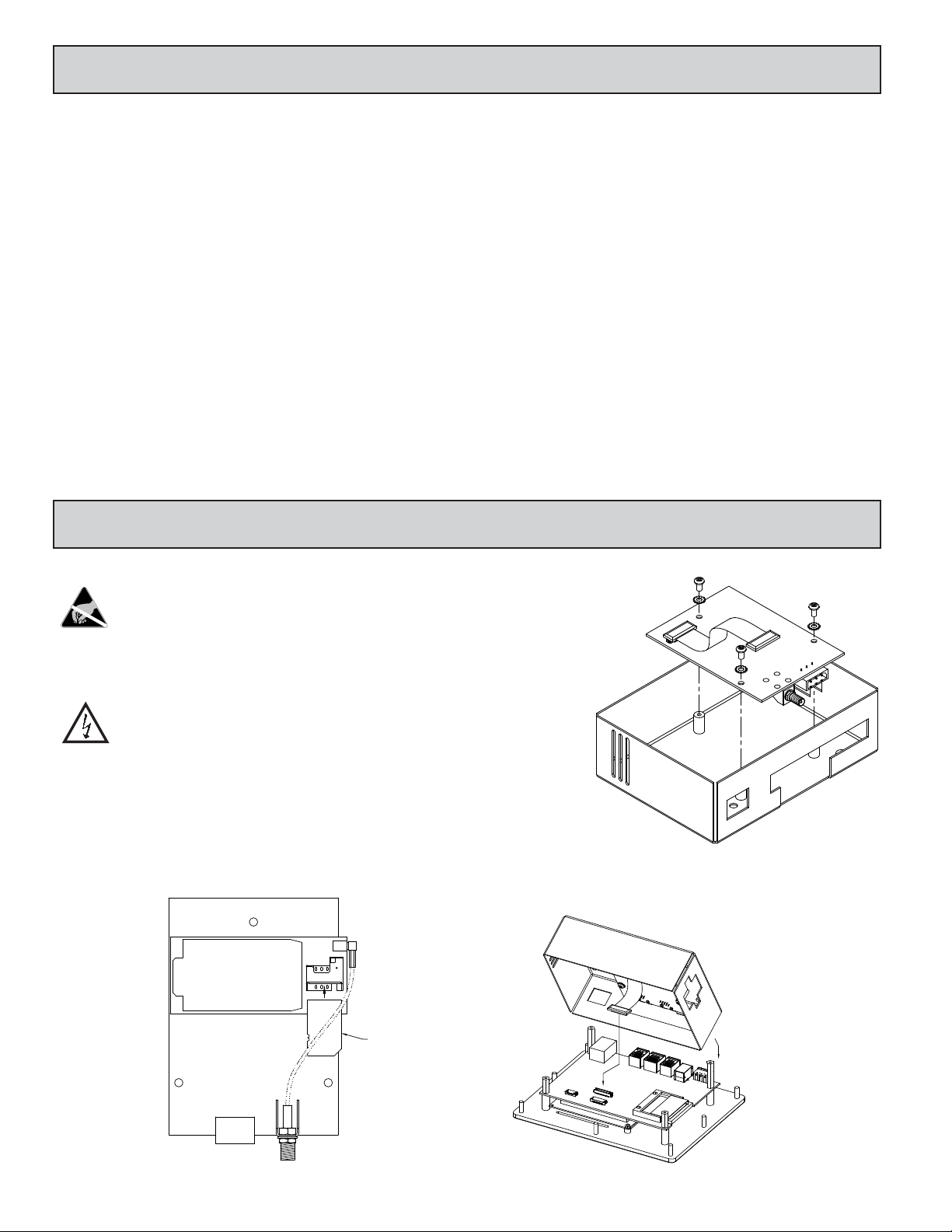
Using the three
screws provided
connect the option
card to the rear
cover as shown in
Figure 2.
Connect the cable from the option card to CN11 on the main board of the G3
operator interface as shown in Figure 3. Be sure both ends of the cables are
firmly seated into their appropriate connector housing.
Figure 2
Figure 1
GSM/GPRS CELL MODEM
GSGSM000 OPTION CARD
POWER
ANTENNA
Figure 3
SIM CARD
2
Page 3

Carefully replace the rear cover by reversing the previous instructions for
removing the rear cover. An external antenna must be attached to the bracket on
the option card as shown in Figure 4. See Antenna Connector in the
Specifications section for more information.
Figure 4
THE OPTION CARD LABEL
Place the option card label on your rear cover in the space indicated by the
dashed lines and labeled “COMMS EXP ANSION MODULE.” The label would
also display the FCC ID of the particular modem being used.
RS232
COMMS EXPANSION MODULE
RS485
RS232
POWER SUPPLY REQUIREMENTS
NEW AND EXISTING INSTALLATIONS
The G3GSM option card needs 24 V power independently of the G3. Wires
should be jumpered from the 24 V main supply of the G3 to the option card. The
power connections described above are absolutely essential to prevent any
ground loops. The 24 V power terminal connector for the G3GSM option card
is shown below.
2 24V ± 20%
1 COMMON
3 N/C
POWER
CONNECTOR
SOFTWARE/UNIT OPERATION
CRIMSON SOFTWARE
Crimson 2.0 software is available as a free download from www.redlion.net
or it can be purchased on a CD, see “Ordering Information” for part number. The
latest version of the software is always available from the web site, and updating
your copy is free.
LED
The G3GSM option card has an LED through the back cover once the option
card is installed. The status of the LED is described in the table below.
LED STATUS
OFF Modem in OFF mode
ON Permanent
SLOW FLASH
QUICK FLASH
LED ON for 200 msec,
OFF for 2 sec
LED ON for 200 msec,
OFF for 600 msec.
Modem switched on, not registered
on the network
Modem switched on, registered on
the network
Modem switched on, registered on
the network and communication is
in progress.
CONFIGURING A G3GSM OPTION CARD
a free download from www.redlion.net, or it can be ordered on CD. Updates to
Crimson for new features and drivers are posted on the website as they become
available. By configuring the G3GSM using the latest version of Crimson 2.0,
you are assured that your unit has the most up to date feature set. Crimson 2.0
software can configure the G3GSM through the option card selection. After
choosing the Cellular Modem option card, it is set up as a PPP Modem client,
PPP Modem Server or SMS via GSM Modem. Find additional information in
your G3 operator interface hardware literature and the Crimson 2.0 manual.
(850/1900 MHz) by default. During setup of the Cellular Modem option card,
the appropriate GSM/GPRS frequency band must be chosen depending on the
geographical location of the G3 operator interface terminal. Once the option
card is configured through Crimson software, it needs to be downloaded to the
G3 terminal. The G3 with the G3GSM option card needs to be power cycled for
the configuration changes with respect to the GSM/GPRS frequency band to
take effect.
SIM CARD INSTALLATION & DETAILS
the option card in the G3 operator interface.
3
The G3GSM is configured using Crimson software. Crimson is available as
All G3GSM option cards are configured to US GSM/GPRS frequency band
A SIM Card has to be installed on the G3GSM option card before installing
Page 4

TROUBLESHOOTING YOUR G3GSM OPTION CARD
If for any reason you have trouble operating, connecting, or simply have questions concerning your new
G3GSM option card, contact Red Lion’s technical support. For contact information, refer to the back page
of this bulletin for phone and fax numbers.
EMAIL: techsupport@redlion.net
Web Site: http://www.redlion.net
The Company warrants the products it manufactures against defects in materials and workmanship
LIMITED WARRANTY
for a period limited to two years from the date of shipment, provided the products have been stored,
handled, installed, and used under proper conditions. The Company’s liability under this limited
warranty shall extend only to the repair or replacement of a defective product, at The Company’s
option. The Company disclaims all liability for any affirmation, promise or representation with
respect to the products.
The customer agrees to hold Red Lion Controls harmless from, defend, and indemnify RLC against
damages, claims, and expenses arising out of subsequent sales of RLC products or products
containing components manufactured by RLC and based upon personal injuries, deaths, property
damage, lost profits, and other matters which Buyer, its employees, or sub-contractors are or may be
to any extent liable, including without limitation penalties imposed by the Consumer Product Safety
Act (P.L. 92-573) and liability imposed upon any person pursuant to the Magnuson-Moss Warranty
Act (P.L. 93-637), as now in effect or as amended hereafter.
No warranties expressed or implied are created with respect to The Company’s products except those
expressly contained herein. The Customer acknowledges the disclaimers and limitations contained
herein and relies on no other warranties or affirmations.
Red Lion Controls
Headquarters
20 Willow Springs Circle
York PA 17406
Tel +1 (717) 767-6511
Fax +1 (717) 764-0839
Red Lion Controls
Europe
Printerweg 10
NL - 3821 AD Amersfoort
Tel +31 (0) 334 723 225
Fax +31 (0) 334 893 793
Red Lion Controls
India
54, Vishvas Tenement
GST Road, New Ranip,
Ahmedabad-382480 Gujarat, India
Tel +91 987 954 0503
Fax +91 79 275 31 350
Red Lion Controls
China
Unit 101, XinAn Plaza
Building 13, No.99 Tianzhou Road
ShangHai, P.R. China 200223
Tel +86 21 6113-3688
Fax +86 21 6113-3683
 Loading...