

Red Lion G3DN User Manual
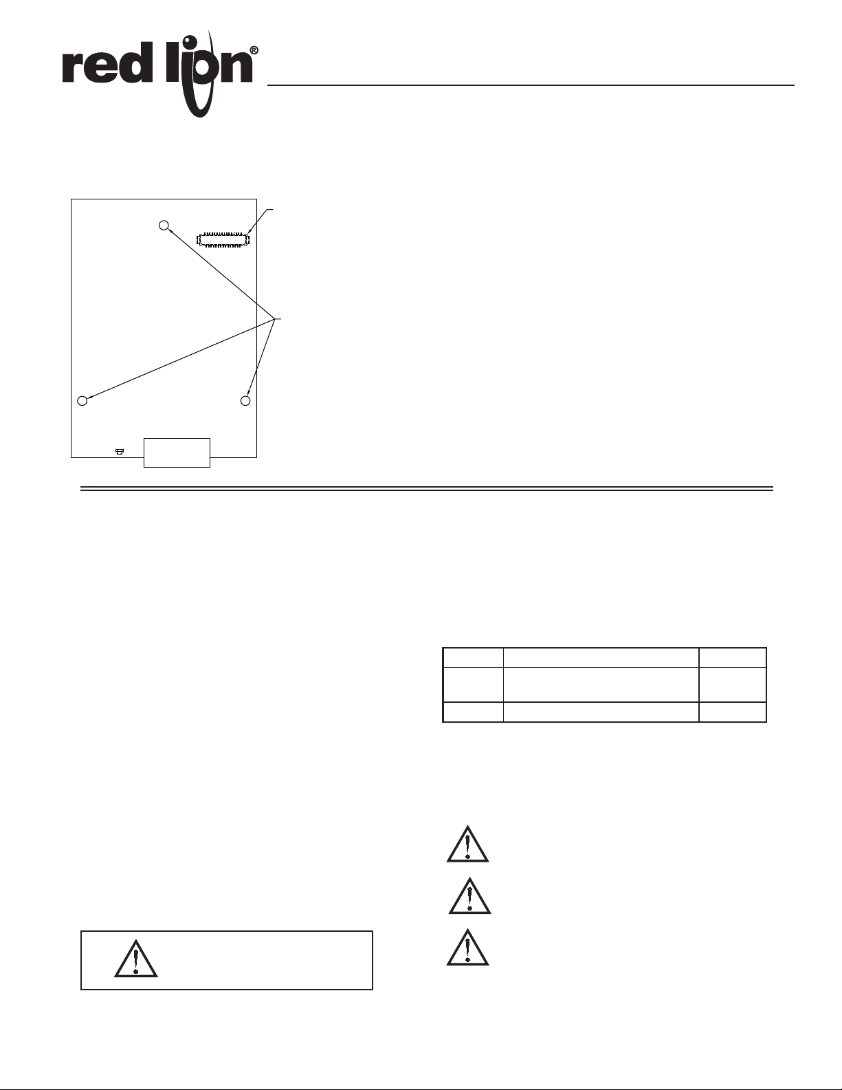
Connector
(side 2)
mounting holes, 3 plcs.
Bulletin No. G3DN-C
Drawing No. LP0632
Released 10/10
Tel +1 (717) 767-6511
Fax +1 (717) 764-0839
www.redlion.net
MODEL G3DN - DeviceNet OPTION CARD FOR G3 OPERATOR
INTERFACE TERMINALS
CONFIGURED USING CRIMSON SOFTWARE
DIGITALLY ISOLATED DEVICENET PORT CAPABLE OF
COMMUNICATING WITH ANY DEVICENET MASTER
POWERED AND CONFIGURED FROM G3 OPERATOR
INTERFACE TERMINAL
INSTALLATION AND CONNECTION HARDWARE INCLUDED
WITH CARD
GENERAL DESCRIPTION
The G3 proprietary expansion slot provides a high speed, parallel architecture
that extends the functionality and flexibility of the G3 series HMI. This
approach allows the G3 series to evolve concurrently with the latest advances in
communications and standards, without sacrificing performance. This high
bandwidth channel has significantly greater throughput when compared to the
traditional (external) serial gateway approach.
The G3DN option card is easily installed by removing the rear cover of your
G3 operator interface, attaching the card using three screws and connecting a
single cable. Adding this card gives the operator interface a DeviceNet slave
communications port. It is built with digital isolation to protect the operator
interface from the DeviceNet bus and vice versa. It provides the ability to
communicate to any DeviceNet master. A connector housing is provided to
function as a strain relief for the wires that terminate into the five position
connector. The connector is pluggable for easy removal of the G3 operator
interface from the DeviceNet bus, without disturbing communications with
other devices on the bus.
SAFETY SUMMARY
All safety related regulations, local codes and instructions that appear in the
literature or on equipment must be observed to ensure personal safety and to
prevent damage to either the instrument or equipment connected to it. If
equipment is used in a manner not specified by the manufacturer, the protection
provided by the equipment may be impaired.
Do not use the controller to directly command motors, valves, or other
actuators not equipped with safeguards. To do so can be potentially harmful to
persons or equipment in the event of a fault to the controller.
CONTENTS OF PACKAGE
- G3DN Option Card with pluggable connector
- Cable already attached to G3DN option card
- Hardware pack consisting of three screws and a connector housing for the
pluggable connector
- This hardware bulletin
ORDERING INFORMATION
MODEL NO. DESCRIPTION PART NUMBER
G3DN
SFCRM2 Crimson 2.0
1
Use this part number to purchase Crimson on CD with a printed
DeviceNet option card for G3 operator
interfaces with isolated high speed
communications ports
1
manual, USB cable, and RS-232 cable. Otherwise, download from www.
redlion.net/g3.
THIS EQUIPMENT IS SUITABLE FOR USE IN CLASS I,
DIVISION 2, GROUPS A, B, C, D, HAZARDOUS LOCATIONS,
OR NON-HAZARDOUS LOCATIONS ONLY
WARNING - EXPLOSION HAZARD - DO NOT DISCONNECT
EQUIPMENT WHILE THE CIRCUIT IS LIVE OR UNLESS THE AREA
IS KNOWN TO BE FREE OF IGNITABLE CONCENTRATIONS.
G3DN0000
SFCRM200
CAUTION: Risk of Danger.
Read complete instructions prior to
installation and operation of the unit.
WARNING - EXPLOSION HAZARD - SUBSTITUTION OF ANY
COMPONENT MAY IMPAIR SUITABILITY FOR CLASS I,
DIVISION 2
1
SPECIFICATIONS
1. POWER REQUIREMENTS:
Power is supplied to the option card from the main board of your G3 operator
interface.
2. COMMUNICATIONS:
DeviceNet Port: The DeviceNet port has format and baud rates that are
software programmable up to 500K baud and are digitally isolated. This
port may be configured for various DeviceNet protocols. Check www.
redlion.net/g3 for currently supported protocols.
Isolation from G3DN Communication ports to G3 operator interface:
1000 VDC for 1 minute.
3. ENVIRONMENTAL CONDITIONS:
Operating Temperature Range: 0 to 50°C
Storage Temperature Range: -20 to 80°C
Operating and Storage Humidity: 80% maximum relative humidity (non-
condensing) from 0 to 50°C.
Altitude: Up to 2000 meters.
4. CERTIFICA TIONS AND COMPLIANCES:
ELECTROMAGNETIC COMPATIBILITY
Emissions and Immunity to EN 61326: Electrical Equipment for Measurement,
Control and Laboratory use.
Immunity to Industrial Locations: Reference G3 unit for emissions and
immunity specifications
5. CONSTRUCTION: Installation Category I, Pollution Degree 2.
6. INSTALLATION REQUIREMENTS: Card must be installed inside the
rear cover of a G3 operator interface with the hardware provided. See
“Installing the G3DN Option Card” for more details.
INSTALLING THE G3DN OPTION CARD
INSTALLATION INSTRUCTIONS
Caution: The option and main circuit boards contain static
sensitive components. Before handling the cards, discharge
static charges from your body by touching a grounded bare
metal object. Ideally, handle the cards at a static controlled clean
workstation. Also, handle the cards by the edges only. Dirt, oil,
or other contaminants that may contact the cards can adversely
affect circuit operation.
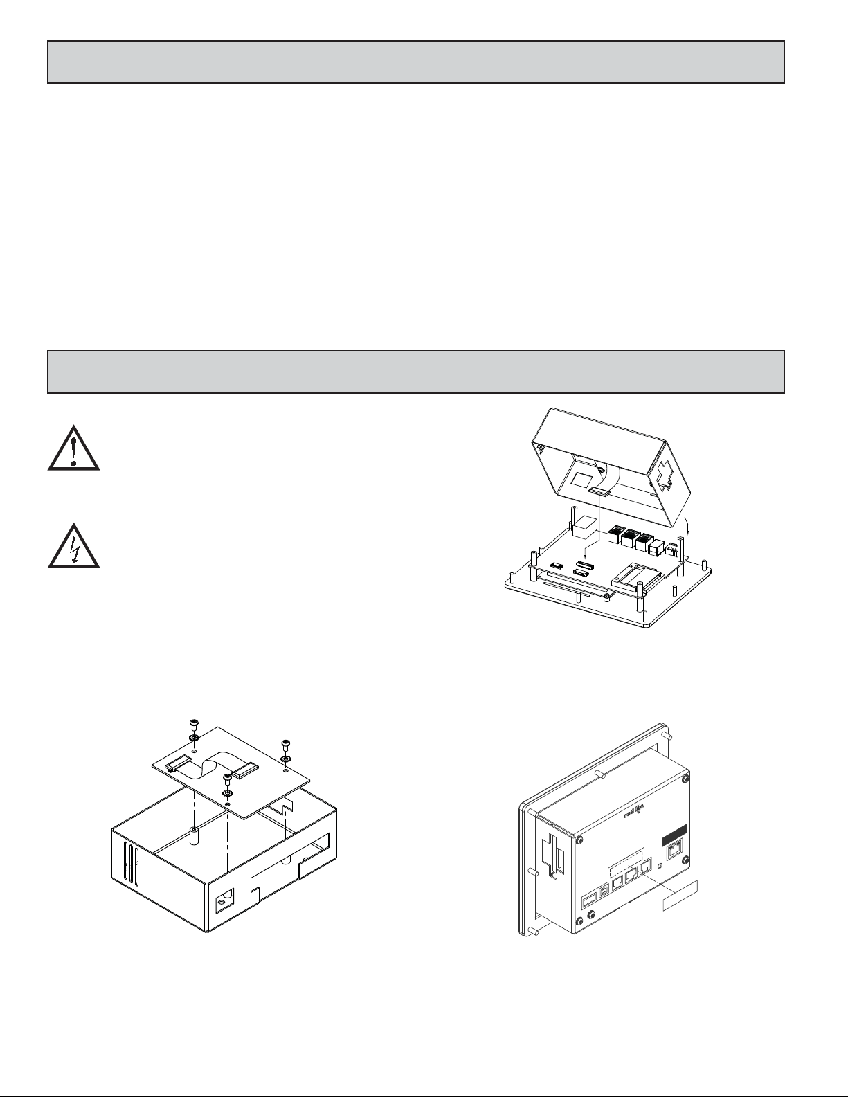
Figure 2
Warning: Depending upon the G3 operator interface, high voltage
may be present inside the operator interface. Be sure to remove
all power before removing the rear cover of the operator interface.
Emissions EN 55011 Class A.
Each G3DN option card comes with a cable for communications and three
screws for attaching the option card to the inside of the G3 operator interface's
rear cover.
To install the option card, remove all power and I/O communications cables
from the unit. The G3 operator interface literature contains instructions for
removing the rear cover. Refer to the “Battery & Time Keeping” section.
Using the three screws provided, connect the option card to the rear cover as
shown in Figure 1.
Figure 1
Carefully replace the rear cover by reversing the instructions for removing the
rear cover.
THE OPTION CARD LABEL
Place the option card label on your rear cover in the space indicated by the
dashed lines and labeled “COMMS EXPANSION MODULE.”
RS232
COMMS EXPANSION MODULE
RS485
RS232
Connect the cable from the option card to CN11 on the main board of the G3
operator interface as shown in Figure 2. Be sure both ends of the cable are firmly
seated into their appropriate connector housings.
POWER SUPPLY REQUIREMENTS
NEW AND EXISTING INSTALLATIONS
The G3DN option card draws all of its power from the main board of your G3
operator interface. The specifications of your G3 operator interface account for
the power needs of an option card.
2
 Loading...