

red lion G315C User Manual
Bulletin No. G315C-C
Drawing No. LP0708
Released 05/09
Tel +1 (717) 767-6511
Fax +1 (717) 764-0839
www.redlion.net
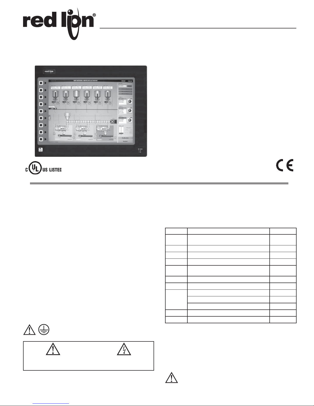
MODEL G315C - GRAPHIC COLOR LCD OPERATOR INTERFACE TERMINAL
WITH TFT XGA DISPLAY AND TOUCHSCREEN
CONFIGURED USING CRIMSON® SOFTWARE
(VERSION 2.0 OR LATER)
UP TO 6 RS-232/422/485 COMMUNICATIONS PORTS
(2 RS-232 AND 2 RS-422/485 ON BOARD, 1 RS-232 AND 1
RS422/485 ON OPTIONAL COMMUNICATIONS CARD)
10 BASE T/100 BASE-TX ETHERNET PORT SUPPORTS
MULTIPLE PROTOCOLS SIMULTANEOUSLY
BUILT-IN WEB SERVER AND FTP SERVER/CLIENT
USB PORT TO DOWNLOAD THE UNIT’S CONFIGURATION FROM
A PC OR FOR DATA TRANSFERS TO A PC
UNIT’S CONFIGURATION IS STORED IN NON-VOLATILE
MEMORY (32 MBYTE FLASH)
COMPACTFLASH® SOCKET FOR DATABASE/RECIPE STORAGE
AND DATA LOGGING
15-INCH TFT ACTIVE MATRIX 32K COLOR XGA 1024 X 768
PIXEL LCD
10-BUTTON KEYPAD FOR ON-SCREEN MENUS
THREE FRONT PANEL LED INDICATORS
POWERED BY 24 VDC ±20% SUPPLY
RESISTIVE ANALOG TOUCHSCREEN
LABORATORY EQUIPMENT
63YN
FOR USE IN HAZARDOUS LOCATIONS:
Class I, Division 2, Groups A, B, C, and D
GENERAL DESCRIPTION
The G315C Operator Interface combines powerful features normally found
only in PC-based HMIs, with the reliability of a dedicated operating system. It
is built around a high performance core with integrated features, allowing it to
provide SCADA-like functionality at a fraction of the cost.
The G315C is able to act as a multiple protocol converter using four highspeed RS232/422/485 communications ports and an Ethernet 10/100 Base-TX
port. The Ethernet port supports up to four protocols simultaneously, allowing
dissimilar Ethernet based products to communicate with one another.
The G315C's USB port allows fast downloads of configuration files and
access to trending and data logging. A CompactFlash socket is provided so that
standard ComplactFlash cards can be used to collect your trending and data
logging information as well as to store configuration files. The built-in web
server allows processes to be controlled remotely.
The G315C's large, high-resolution display allows users to easily view and
enter information. Data can be manipulated through the touchscreen and/or the
10-button keypad.
SAFETY SUMMARY
All safety related regulations, local codes and instructions that appear in the
manual or on equipment must be observed to ensure personal safety and to
prevent damage to either the instrument or equipment connected to it. If
equipment is used in a manner not specified by the manufacturer, the protection
provided by the equipment may be impaired.
Do not use the controller to directly command motors, valves, or other
actuators not equipped with safeguards. To do so can be potentially harmful to
persons or equipment in the event of a fault to the controller.
The protective conductor terminal is bonded to conductive
parts of the equipment for safety purposes and must be
connected to an external protective earthing system.
CAUTION: Risk Of Danger.
Read complete instructions prior to
installation and operation of the unit.
CompactFlash is a registered trademark of CompactFlash Association.
CAUTION: Risk of electric shock.
CONTENTS OF PACKAGE
- G315C Operator Interface.
- Panel gasket.
- Template for panel cutout.
- Hardware packet for mounting unit into panel.
- Terminal block for connecting power.
ORDERING INFORMATION
MODEL NO. DESCRIPTION PART NUMBER
G315C
G3CF CompactFlash Card
G3RS RS232/485 Optional Communication Card G3RS0000
G3CN CANopen Optional Communication Card G3CN0000
G3DN
G3PBDP Profibus DP Optional Communication Card G3PBDP00
SFCRM2 Crimson 2.0
CBL
DR DIN Rail Mountable Adapter Products
1
Contact your Red Lion distributor or visit our website for complete
selection.
2
Use this part number to purchase Crimson on CD with a printed
manual, USB cable, and RS-232 cable. Otherwise, download for free from
www.redlion.net.
3
Red Lion offers RJ modular jack adapters. Refer to the DR literature for
complete details.
4
Battery type is lithium coin type CR2025.
5
Industrial grade two million write cycles. SMART Modular Technologies
model SG9CF (UL Listed Directory Category NWGQ).
Operator Interface for indoor applications,
textured finish with embossed keys
5
DeviceNet option card for G3 operator interfaces
with isolated high speed communications ports
2
RS-232 Programming Cable CBLPROG0
USB Cable CBLUSB00
Communications Cables
Replacement Battery
1
3
4
G315C000
G3CFxxxx
G3DN0000
SFCRM200
CBLxxxxx
DRxxxxxx
BNL20000
WARNING - EXPLOSION HAZARD - SUBSTITUTION OF
COMPONENTS MAY IMPAIR SUITABILITY FOR CLASS I,
DIVISION 2
1
SPECIFICATIONS
1. POWER REQUIREMENTS:
Must use Class 2 or SELV rated power supply.
Power connection via removable three position terminal block.
Supply Voltage: +24 VDC ±20%
Typical Power
Maximum Power2: 67 W
Notes:
1. Typical power with +24 VDC, RS232/485 communications, Ethernet
2. Maximum power indicates the most power that can be drawn from the
3. The G315C’s circuit common is not connected to the enclosure of the
4. Read “Power Supply Requirements” in the section “Installing and
2. BATTERY: Lithium coin cell. Typical lifetime of 10 years.
3. LCD DISPLAY:
SIZE
TYPE
COLORS
PIXELS
BRIGHTNESS
BACKLIGHT*
*Lifetime at room temperature. Refer to “Display” in “Software/Unit Operation”
4. 10-KEY KEYPAD: for on-screen menus.
5. TOUCHSCREEN: Resistive analog
6. MEMORY:
On Board User Memory: 32 Mbyte of non-volatile Flash memory.
Memory Card: CompactFlash Type II slot for Type I and Type II
CompactFlash cards.
7. COMMUNICATIONS:
USB Device Port: Adheres to USB 2.0 Specification supporting high speed
and full speed via Type B connection.
Serial Ports: Format and Baud Rates for each port are individually software
programmable up to 115,200 baud.
PGM Port: RS232 port via RJ12.
COMMS Ports: RS422/485 port via RJ45, and RS232 port via RJ12.
DH485 TXEN: Transmit enable; open collector, VOH = 15 VDC,
Note: For additional information on the communications or signal
Port to port isolation: 500 Vrms for 1 minutes signal isolation : 50V
Ethernet Port: 10 BASE-T / 100 BASE-TX
RJ45 jack is wired as a NIC (Network Interface Card).
Isolation from Ethernet network to G3 operator interface: 1500 Vrms
8. ENVIRONMENTAL CONDITIONS:
Operating Temperature Range: 0 to 50 °C
Storage Temperature Range: -20 to 70 °C
1
: 27 W
communications, CompactFlash card installed, and display at full brightness.
G315C. Refer to “Power Supply Requirements” under “Installing and
Powering the G315C.”
unit. See “Connecting to Earth Ground” in the section “Installing and
Powering the G315C.”
Powering the G315C” for additional power supply information.
15-inch
TFT
32K
1024 X 768
50,000 HR TYP.
WARNING - DO NOT CONNECT OR DISCONNECT CABLES WHILE
POWER IS APPLIED UNLESS AREA IS KNOWN TO BE NON-
HAZARDOUS. USB PORT IS FOR SYSTEM SET-UP AND
DIAGNOSTICS AND IS NOT INTENDED FOR PERMANENT
CONNECTION.
600 cd/m
2
VOL = 0.5 V @ 25 mA max.
common and connections to earth ground please see the “Connecting to
Earth Ground” in the section “Installing and Powering the G315C.”
Operating and Storage Humidity: 80% maximum relative humidity (non-
condensing) from 0 to 50°C.
Vibration according to IEC 68-2-6: Operational 5 to 150 Hz, in X, Y, Z
direction for 1.5 hours, 2 g’s.
Shock according to IEC 68-2-27: Operational 35 g’s, 9 msec in 3 directions.
Altitude: Up to 2000 meters.
9. CERTIFICA TIONS AND COMPLIANCES:
SAFETY
UL Recognized Component, File #E179259, UL61010-1, CSA 22.2 No.61010-1
Recognized to U.S. and Canadian requirements under the Component
Recognition Program of Underwriters Laboratories, Inc.
UL Listed, File #E211967, UL61010-1, ANSI/ISA 12.12.01-2007, CSA 22.2
No. 61010.1, CSA 22.2 No. 213-M1987
LISTED by Und. Lab. Inc. to U.S. and Canadian safety standards
Type 4X Enclosure rating (Face only), UL50
IECEE CB Scheme Test Certificate #US/12460C/UL,
CB Scheme Test Report #E179259-A1-CB-1
Issued by Underwriters Laboratories Inc.
IEC 61010-1, EN 61010-1: Safety requirements for electrical equipment
for measurement, control, and laboratory use, Part 1.
IP66 Enclosure rating (Face only), IEC 529
ELECTROMAGNETIC COMPATIBILITY
Emissions and Immunity to EN 61326: Electrical Equipment for Measurement,
Control and Laboratory use.
Immunity to Industrial Locations:
Criterion AEN 61000-4-2Electrostatic discharge
4 kV contact discharge
8 kV air discharge
Criterion BEN 61000-4-3Electromagnetic RF fields
10 V/m
Criterion BEN 61000-4-4Fast transients (burst)
2 kV power
1 kV signal
Criterion AEN 61000-4-5Surge
1 kV L-L,
2 kV L&N-E power
Criterion BEN 61000-4-6RF conducted interference
3 V/rms
Emissions:
Class AEN 55011Emissions
Note:
1. Criterion A: Normal operation within specified limits.
2. Criterion B: Temporary loss of performance from which the unit self
recovers.
10. CONNECTIONS: Compression cage-clamp terminal block.
Wire Gage: 12-22 AWG copper wire
Torque: 5-7 inch-pounds (56-79 N-cm)
11. CONSTRUCTION: Steel rear metal enclosure with NEMA 4X/IP66
aluminum front plate for indoor use only when correctly fitted with the gasket
provided. Installation Category II, Pollution Degree 2.
12. MOUNTING REQUIREMENTS: Maximum panel thickness is 0.25" (6.3
mm). For NEMA 4X/IP66 sealing, a steel panel with a minimum thickness of
0.125" (3.17 mm) is recommended.
Maximum Mounting Stud Torque: 17 inch-pounds (1.92 N-m)
13. WEIGHT: 11.41 lbs (5.17 Kg)
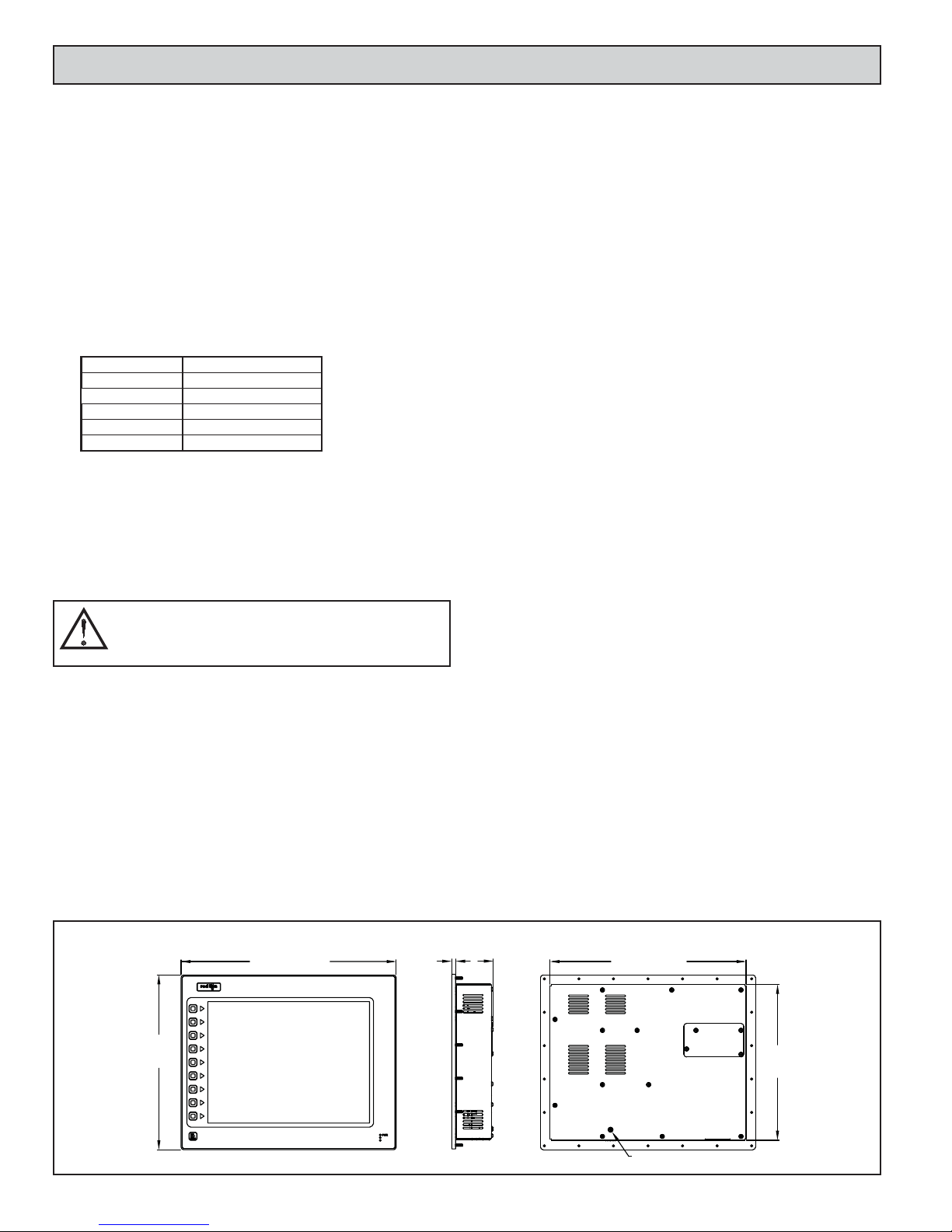
DIMENSIONS In inches (mm)
16.00 (406.4)
13.00
(330.2)
.28
(7.1)
2.8
(71.5)
2
14.59 (370.6)
11. 59
(294.4)
PROTECTIVE EARTH GROUND
INSTALLING AND POWERING THE G315C
ISOLATED
ETHERNET
AUXILIARY
ISOLATED
RS232
PORT B
F G
ETHERNET
ISOLATED
ISOLATED
D E
B
RS485
PORT B
C
A
HOST B
A
PGM PORT
ISOLATED
RS232
PORT A
ISOLATED
-
+
24VDC
SUPPLY
PORT A
RS485
A
POWER
PROGRAMMING
HOST A
A
USB DEVICE
MOUNTING INSTRUCTIONS
This operator interface is designed for through-panel mounting. A panel cutout diagram and a template are provided. Care should be taken to remove any
loose material from the mounting cut-out to prevent that material from falling
into the operator interface during installation. A gasket is provided to enable
sealing to NEMA 4X/IP66 specification. Install the 22 kep nuts provided and
tighten evenly for uniform gasket compression.
Note: Tightening the kep nuts beyond a maximum of 17 inch-pounds (1.92
N-m) may cause damage to the front panel.
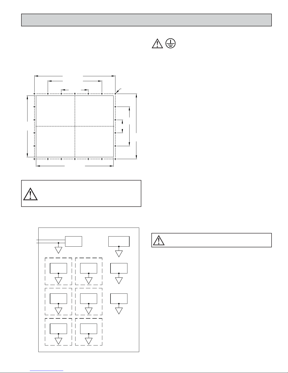
15.425 (391.8)
10.283 (261.2)
22X ∅.188
(∅4.8)
2.485
(63.1)
7.455
(189.4)
12.425
(315.6)
11.720
(297.7)
5.142 (130.6)
14.720 (373.9)
All tolerances ±0.010" (±0.25 mm).
ALL NONINCENDIVE CIRCUITS MUST BE WIRED USING
DIVISION 2 WIRING METHODS AS SPECIFIED IN ARTICLE 501-4
(b), 502-4 (b), AND 503-3 (b) OF THE NATIONAL ELECTRICAL
CODE, NFPA 70 FOR INSTALLATION WITHIN THE UNITED
STATES, OR AS SPECIFIED IN SECTION 19-152 OF CANADIAN
ELECTRICAL CODE FOR INSTALLATION IN CANADA.
BLOCK DIAGRAM
CONNECTING TO EARTH GROUND
The protective conductor terminal is bonded to conductive
parts of the equipment for safety purposes and must be
connected to an external protective earthing system.
Each G315C has a chassis ground terminal on the back of the unit. Your unit
should be connected to earth ground (protective earth).
The chassis ground is not connected to signal common of the unit.
Maintaining isolation between earth ground and signal common is not required
to operate your unit. But, other equipment connected to this unit may require
isolation between signal common and earth ground. To maintain isolation
between signal common and earth ground care must be taken when connections
are made to the unit. For example, a power supply with isolation between its
signal common and earth ground must be used. Also, plugging in a USB cable
may connect signal common and earth ground.
1
USB’s shield may be connected to earth ground at the host. USB’s shield
1
in turn may also be connected to signal common.
POWER SUPPLY REQUIREMENTS
The G315C requires a 24 VDC power supply. Your unit may draw
considerably less than the maximum rated power depending upon the options
being used. As additional features are used your unit will draw increasing
amounts of power. Items that could cause increases in current are additional
communications, optional communications card, CompactFlash card, and other
features programmed through Crimson.
In any case, it is very important that the power supply is mounted correctly if
the unit is to operate reliably. Please take care to observe the following points:
– The power supply must be mounted close to the unit, with usually not
more than 6 feet (1.8 m) of cable between the supply and the operator
interface. Ideally, the shortest length possible should be used.
– The wire used to connect the operator interface’s power supply should
be at least 22-gage wire. If a longer cable run is used, a heavier gage
wire should be used. The routing of the cable should be kept away from
large contactors, inverters, and other devices which may generate
significant electrical noise.
– A power supply with a Class 2 or SELV rating is to be used. A Class 2
or SELV power supply provides isolation to accessible circuits from
hazardous voltage levels generated by a mains power supply due to
single faults. SEL V is an acronym for “safety extra-low voltage.” Safety
extra-low voltage circuits shall exhibit voltages safe to touch both under
normal operating conditions and after a single fault, such as a
breakdown of a layer of basic insulation or after the failure of a single
component has occurred.
A disconnect device must be provided by the end-user.
3
 Loading...