

red lion G310C, TX700T Replacement Procedure
Tel +1 (717) 767-6511
r
Fax +1 (717) 764-0839
www.redlion.net
G310C & TX700T BACKLIGHT ASSEMBLIES
Bulletin No. G310BK-D
Drawing No. LP0612
Released: 08/13
CAUTION - Backlight is not field replaceable for hazardous
location applications. Unit must be returned to Red Lion
Controls for repair.
WARNING - EXPLOSION HAZARD - DO NOT DISCONNECT
EQUIPMENT UNLESS POWER HAS BEEN DISCONNECTED
AND THE AREA IS KNOWN TO BE NON-HAZARDOUS.
G310 BACKLIGHT REPLACEMENT PROCEDURE
1. Remove the power and PLC Communications connectors from the unit.
2. Remove the five screws from the rear cover.
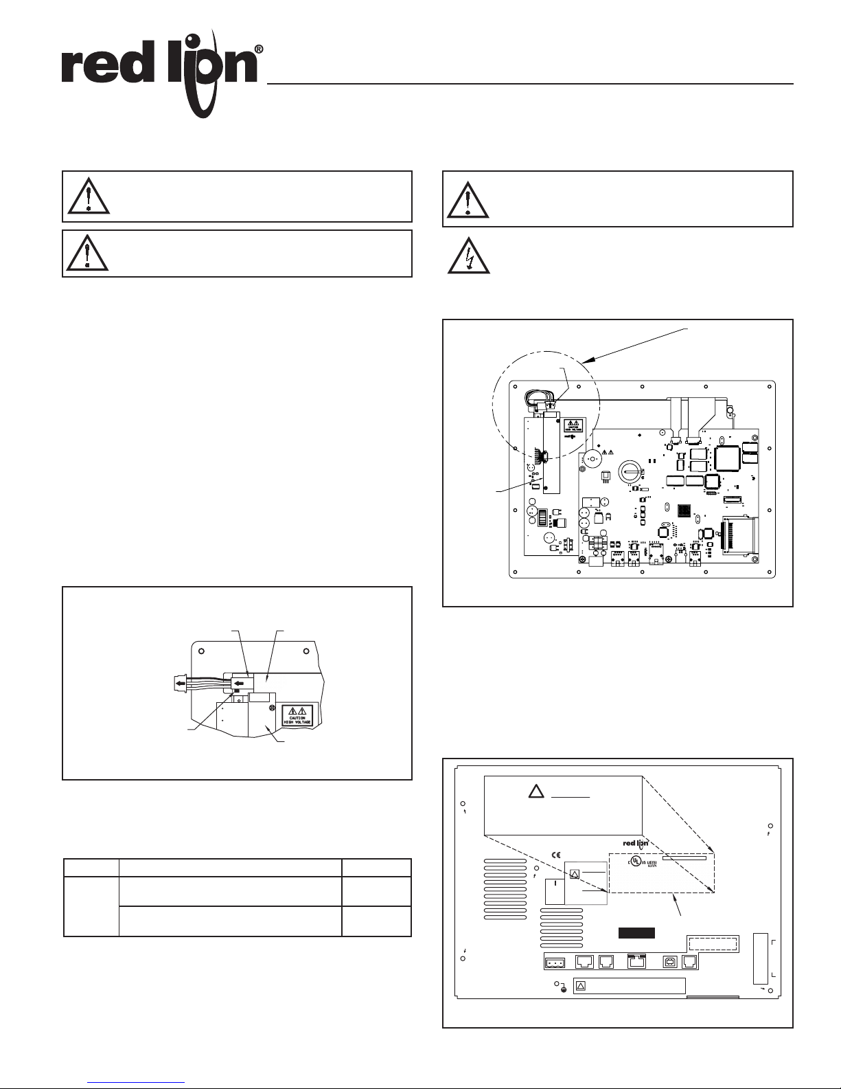
3. Locate the inverter board (refer to Figure 1).
4. Carefully remove heat shrink tubing from the backlight connector on the
inverter board.
5. Carefully remove the backlight connector from its connector housing on the
inverter board. (refer to Figure 1).
6. Depress the backlight release tab and carefully remove the backlight as
indicated in Figure 2.
7. To install the new backlight assembly, reverse the above steps. Ensure that the
florescent tubes of the backlight assembly face towards the display. Use
caution when inserting the new assembly so that it is not twisted or pushed
on an angle. The backlight assembly is fragile and may easily be broken.
8. Apply the enclosed label to the rear cover in the area indicated in Figure 3.
Field replacement of the backlight assembly voids the Hazardous Locations
rating of this unit.
WARNING - EXPLOSION HAZARD - THE AREA MUST BE KNOWN
TO BE NON-HAZARDOUS BEFORE SERVICING/ REPLACING
THE UNIT AND BEFORE INSTALLING OR REMOVING I/O,
INVERTER, BACKLIGHT, WIRING AND BATTERY.
CAUTION: RISK OF ELECTRIC SHOCK
The inverter board supplies the high voltage to operate the
backlight. Touching the inverter board may result in injury to
personnel. Disconnect all power before installing or removing
backlight assembly.
G310C
Inverter
Board
Backlight
Connector
CAUTION
HIGH VOLTAGE
See Figure 2
G310C
Backlight Display
Release
Tab
Inverte
Board
Figure 2
ORDERING INFORMATION
MODEL NO. DESCRIPTION PART NUMBER
G310C/TX700T Backlight Tube, NEC-29, -46 only
G310
(Note 1)
G310C/TX700T Backlight Tube, NEC-64R only
(Note 1)
Note 1:
Refer to the part number on the rear of the display in the lower right hand corner.
NEC displays with a part number ending in -29 or -46 must use G3BR10C0.
NEC displays with a part number ending in -64R must use G3BR10C1.
These part numbers are for use with Models G310C and TX700T.
G3BR10C0
G3BR10C1
Figure 1
M3752X
!
M3619X
WARNING
COMMON
24V 20%
POWER SUPPLY
CLASS II POWER SUPPLY
MODEL G310C
!
INPUT POWER
24 20% VDC
33W MAX.
MODEL G310S
INPUT POWER
24 20% VDC
50W MAX.
N/C
321
RS485
RS232 RS232
COMMS PORT
COMMS PORT
DO NOT CONNECT OR DISCONNECT CABLES WHILE POWER
IS APPLIED UNLESS AREA IS KNOWN TO BE NON-HAZARDOUS.
!
USB PORT IS FOR SYSTEM SET-UP AND DIAGNOSTICS
AND IS NOT INTENDED FOR PERMANENT CONNECTION.
The field repairs that have been
made to this unit have voided the
UL LISTED (HAZARDOUS LOCATIONS) rating.
Figure 3
RED LION CONTROLS
www.redlion.net
MADE IN U.S.A.MODEL G310
OPERATING TEMP. CODE T6
AMBIENT = 50° C MAXIMUM
LABORATORY EQUIPMENT FOR USE IN HAZARDOUS LOCATIONS
CL I, DIV 2, GP A,B,C,D/CL II, DIV 2, GP F,G/CL III, DIV 2
ENVIRONMENTAL-IP66 TYPE 4X
IP ADDRESS
Apply label here.
Tx/Rx
LINK
ETHERNET
USB
COMMS EXPANSION MODULE
PGM PORT
TM
INSERT FACE UP
CompactFlash CARD
WHILE POWER IS APPLIED
DO NOT REMOVE OR INSERT
1
TX700T BACKLIGHT REPLACEMENT PROCEDURE
WARNING - EXPLOSION HAZARD - THE AREA MUST BE KNOWN
TO BE NON-HAZARDOUS BEFORE SERVICING/ REPLACING
THE UNIT AND BEFORE INSTALLING OR REMOVING I/O,
INVERTER, BACKLIGHT, WIRING AND BATTERY.
WARNING - EXPLOSION HAZARD - DO NOT DISCONNECT
EQUIPMENT UNLESS POWER HAS BEEN DISCONNECTED
AND THE AREA IS KNOWN TO BE NON-HAZARDOUS.
1. Remove the power and PLC Communications connectors from the unit.
2. Remove the four screws from the rear cover.
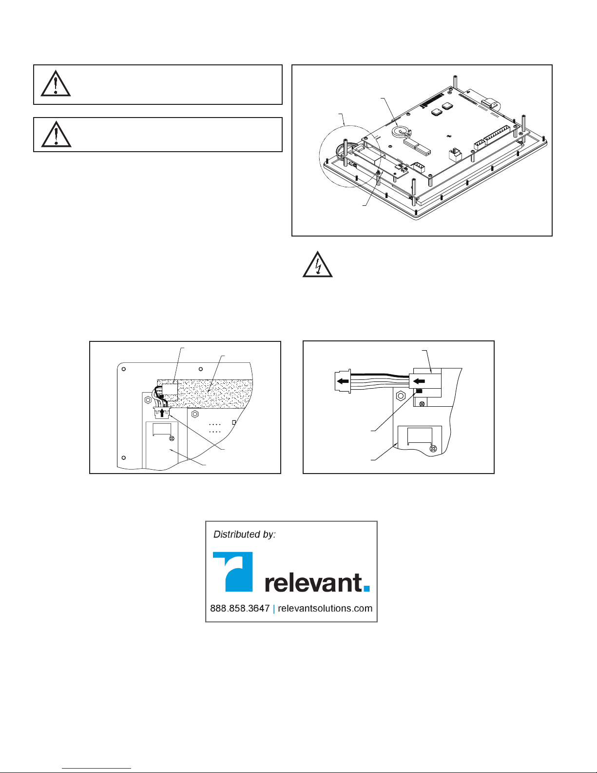
3. Locate the inverter board (refer to Figure 1).
4. Carefully remove the backlight connector from its connector housing on the
inverter board. (refer to Figure 2).
5. Depress the backlight release tab and carefully remove the backlight as
indicated in Figure 3.
6. To install the new backlight assembly, reverse the above steps. Ensure that
the florescent tubes of the backlight assembly face towards the display. Use
caution when inserting the new assembly so that it is not twisted or pushed
on an angle. The backlight assembly is fragile and may easily be broken.
Figure 2
Backlight
Display
Figure 1
See FIGURE 2
Figure 3
Battery Holder
TOUCH SCREEN
Inverter
Board
HIGH VOLTAGE
CAUTION
KEYBOARD INTERFACE
UCS
Bh8
500T
500
1
23
4
5
1
2
3
CAUTION: RISK OF ELECTRIC SHOCK
The inverter board, attached to the mounting plate, supplies the
high voltage to operate the backlight. Touching the inverter
board may result in injury to personnel. Disconnect all power
before installing or removing backlight assembly.
Backlight
Red Lion Controls
Headquarters
20 Willow Springs Circle
York PA 17406
Tel +1 (717) 767-6511
Fax +1 (717) 764-0839
Backlight
Connector
Inverter Board
Red Lion Controls
Europe
Softwareweg 9
NL - 3821 BN Amersfoort
Tel +31 (0) 334 723 225
Fax +31 (0) 334 893 793
Release
Tab
Inverter
Board
Red Lion Controls
India
201-B, 2nd Floor, Park Centra
Opp 32 Mile Stone, Sector-30
Gurgaon-122002 Haryana, India
Tel +91 984 487 0503
Red Lion Controls
China
Unit 302, XinAn Plaza
Building 13, No.99 Tianzhou Road
ShangHai, P.R. China 200223
Tel +86 21 6113 3688
Fax +86 21 6113 3683
 Loading...