

Bulletin No. EPAX6-E
Drawing No. LP0539
Released 05/13
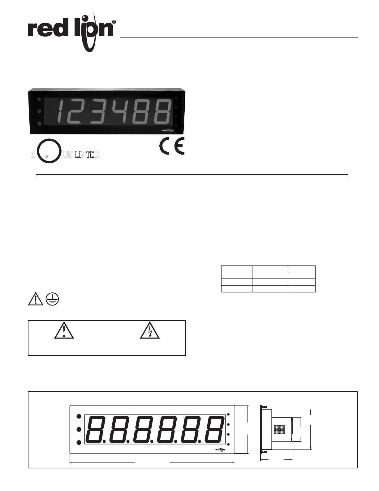
MODEL EPAX- 6 DIGIT EXTRA LARGE PAX DISPLAY FOR DIGITAL INPUTS
LARGE LED DISPLAY READABLE TO 180 FEET
VARIOUS DIGITAL INPUT MODULES;
COUNT AND RATE INPUT
CLOCK/TIMER
SERIAL SLAVE
ALARMS, ANALOG OUTPUT, AND COMMUNICATION
PROGRAMMABLE USER INPUTS
UNIVERSAL AC POWERED (85 to 250 VAC)
PC SOFTWARE FOR METER CONFIGURATION
C
U
R
L
US LISTED
IND. CONT. EQ.
51EB
NEMA 4X/IP65
GENERAL DESCRIPTION
The EPAX Display is a versatile display that can increase productivity by
offering the plant floor or production area a large visual display of their current
status. Whether your measurement is rate, count, or time, the EPAX can satisfy
your requirement. The EPAX displays accept various digital inputs through the
use of input modules (MPAX) which allow the unit to adapt to most any
application. The MPAX Modules offer the same features as our highly
successful PAX Series Panel Meters. Additional plug-in option cards can add
alarms, analog output, and communication/bus capabilities, making the EPAX a
truly Intelligent Panel Meter.
SAFETY SUMMARY
All safety regulations, local codes and instructions that appear in this and
corresponding literature, or on equipment, must be observed to ensure personal
safety and to prevent damage to either the instrument or equipment connected
to it. If equipment is used in a manner not specified by the manufacturer, the
protection provided by the equipment may be impaired.
The protective conductor terminal is bonded to conductive
parts of the equipment for safety purposes and must be
connected to an external protective earthing system.
CAUTION: Risk of Danger.
Read complete instructions prior to
installation and operation of the unit.
CAUTION: Risk of electric shock.
SPECIFICATIONS
Additional specifications, wiring, programming, and information for the
individual MPAX models are contained in the corresponding standard PAX
literature. This PAX literature is shipped with the ordered MPAX model.
1. DISPLAY: 4" (101 mm) Red LED
6-Digit (EPAX0600): (-99999 to 999999)
2. POWER REQUIREMENTS:
AC MPAX Modules: 85 to 250 VAC, 50/60 Hz, 18 VA
EPAX Display: 85 to 250 VAC, 50/60 Hz, 10 VA
3. INPUT: Accepts digital input modules, see “Selecting Your Display
Components and Option Cards.”
4. ANNUNCIATORS:
Display Indication: Three vertical dots on the left side of the unit identify
the displays for the following modules:
COUNT/RATE CLOCK
TOP Display A Timer
MIDDLE Display B Count
BOTTOM Display C Date
Setpoint Indication: Four vertical dots on the right side of the unit identify
the setpoint “ON” condition, with SP 1 being the top position through SP
4 at the bottom.
5. EPAX Programming: The unit is a large display, designed to be remotely
mounted. Therefore, the unit does not have a programming keypad. Unit
programming should be accomplished by one of the following methods:
Rear Terminal Block: External switches can be wired via the terminal block
to allow unit programming. A minimum of 3 switches would be required.
Optional Programming Remote (EPAXPGM0): This option provides a 10
foot interconnecting cable and programming box. The Programming
Remote contains buttons similar to the PAX, allowing easy programming
of the EPAX display.
Optional Serial Programming: Like all PAX units, you can purchase an RS232
or RS485 Comms Card and program the unit via Windows
software programs.
®
based
DIMENSIONS In inches (mm)
24.77 (629.2)
6.09
7.22
(183.4)
4.65
(118.1)
1
3.60
(91.5)
(154.7)
6. CERTIFICATIONS AND COMPLIANCES:
SAFETY
UL Recognized Component, File #E179259, UL61010A-1, CSA C22.2
No. 1010-1
Recognized to U.S. and Canadian requirements under the Component
Recognition Program of Underwriters Laboratories, Inc.
UL Listed, File #E137808, UL508, CSA C22.2 No. 14-M95
LISTED by Und. Lab. Inc. to U.S. and Canadian safety standards
Type 4X Indoor Enclosure rating (Face only), UL50
IECEE CB Scheme Test Certificate #US/8843/UL
CB Scheme Test Report #04ME11209-20041018
Issued by Underwriters Laboratories, Inc.
9. MODULE INSTALLATION:
24-pin shrouded connector on EPAX engages connector on MPAX module
upon installation. Shroud ensures proper alignment by providing a lead-in for
the module connector.
10. CONNECTIONS: Wiring connections are made to the EPAX terminal
block and MPAX module via high compression cage-clamp terminal blocks.
MPAX Module Wiring: Instructions are provided in the corresponding PAX
Bulletin.
EPAX Terminal Block Wiring:
Wire Strip Length: 0.3" (7.5 mm)
Wire Gage: 30-12 AWG copper wire
Maximum Torque: 5-7 inch-lbs (0.58-0.81 N-m)
IEC 61010-1, EN 61010-1: Safety requirements for electrical equipment
for measurement, control, and laboratory use, Part 1.
IP65 Enclosure rating (Face only), IEC 529
CAUTION: DISCONNECT ALL POWER BEFORE
INSTALLING OR REMOVING MODULE
ELECTROMAGNETIC COMPATIBILITY
EMC specifications determined by the MPAX module.
7. ENVIRONMENTAL CONDITIONS:
Operating Temperature Range: Determined by the MPAX module
Storage Temperature Range: -40 to 60°C
Operating and Storage Humidity: 0 to 85% max. RH (non-condensing)
Altitude: Up to 2000 meters
11. CONSTRUCTION: Aluminum front panel, enclosure, and rear cover with
textured black polyurethane paint for scratch and corrosion resistance
protection. Sealed front panel meets NEMA 4X/IP65 specifications for
indoor use when properly installed. Installation Category II, Pollution Degree
2. Panel gasket and keps nuts included.
12. WEIGHT: 5 lbs (2.25 kg) (less module)
8. MOUNTING REQUIREMENTS:
Max. panel thickness is 0.375" (9.5 mm)
Min. panel thickness for NEMA 4/IP65 sealing is 0.060" (1.52 mm)
About the MPAX Input Modules
The MPAX Module serves as the input to the EPAX Display. There are several different modules to cover a variety of inputs. The MPAX module provides input
scaling which allows the EPAX to display most any engineering unit. Once the MPAX is inserted into the EPAX, the unit has the same functions and capabilities of
our PAX Series Intelligent Panel Meters. A full set of PAX programming instructions will be included with the MPAX module.
Selecting Your Display Components and Option Cards
To build a complete display unit, you will need an EPAX and an MPAX Input Module. The EPAX is only a display and will not operate without an MPAX module.
Please use the following chart to identify the appropriate MPAX module and EPAX Display that will satisfy your application.
SIGNAL TYPE
Count/Rate/Serial Slave
Count
Rate
Real-Time Clock/Timer
Timer
MPAX MODULES*
85-250 VAC
MPAXCK00
MPAXTM00
EPAX
DISPLAYS
EPAX0600MPAXI020
EPAX0600MPAXC020
EPAX0600MPAXR020
EPAX0600
EPAX0600
OPTIONAL PLUG-IN CARD COMPATABILITY
YES
-
-
-
-
REAL-TIME
CLOCK
SETPOINT
YES
YES
YES
YES
YES
COMMS
YES
-
-
YES
YES
ANALOG
-
-
-
YES
-
* For detailed module and plug-in card specifications,
see corresponding PAX literature. (i.e. For MPAXI
specifications, see the PAXI literature)
OPTIONAL PLUG-IN CARDS AND ACCESSORIES
WARNING: Disconnect all power to the unit before
installing Plug-in cards.
Adding Option Cards
The PAX and MPAX series meters can be fitted with up to three optional plug-
in cards. The details for each plug-in card can be reviewed in the specification
section of the PAX Bulletin. Only one card from each function type can be
installed at one time. The function types include Setpoint Alarms (PAXCDS),
Communications (PAXCDC), and Analog Output (PAXCDL). The plug-in cards
can be installed initially or at a later date.
SETPOINT ALARMS PLUG-IN CARDS (PAXCDS)
The PAX and MPAX series has 4 available setpoint alarm output plug-in
cards. Only one of these cards can be installed at a time. (Logic state of the
outputs can be reversed in the programming.) These plug-in cards include:
PAXCDS10 - Dual Relay, FORM-C, Normally open & closed
PAXCDS20 - Quad Relay, FORM-A, Normally open only
PAXCDS30 - Isolated quad sinking NPN open collector
PAXCDS40 - Isolated quad sourcing PNP open collector
ANALOG OUTPUT PLUG-IN CARD (PAXCDL)
Either a 0(4)-20 mA or 0-10 V retransmitted linear DC output is available
from the analog output plug-in card. The programmable output low and high
scaling can be based on various display values. Reverse slopes output is possible
by reversing the scaling point positions.
PAXCDL10 - Retransmitted Analog Output Card
COMMUNICATION PLUG-IN CARDS (PAXCDC)
A variety of communication protocols are available for the PAX and MPAX
series. Only one of these cards can be installed at a time. When programming the
unit via Crimson (for MPAXI) or SFPAX (for MPAXCK or MPAXTM), the
RS232 or RS485 Cards must be used.
MPAXI/C/R Note: For Modbus communications, use RS485 Communications
Output Card and configure Communication Type parameter (tYPE) for Modbus.
PAXCDC10 - RS485 Serial (Terminal) PAXCDC1C - RS485 Serial (Connector)
PAXCDC20 - RS232 Serial (Terminal) PAXCDC2C - RS232 Serial (Connector)
PAXCDC30 - DeviceNet
* PAXCDC40 - Modbus (Terminal) * PAXCDC4C - Modbus (Connector)
PAXCDC50 - Profibus-DP
* MPAXCK/MPAXTM only.
PROGRAMMING SOFTWARE
CRIMSON - MPAXI Only
Crimson is a Windows® based program that allows configuration of the
EPAX meter from a PC. Crimson offers standard drop-down menu commands,
that make it easy to program the EPAX meter. The EPAX program can then be
saved in a PC file for future use. A PAX serial plug-in card is required to
program the meter using the software.
SFPAX - MPAXCK and MPAXTM Only
The SFPAX is a Windows® based program that allows configuration of the
EPAX meter from a PC. Using the SFPAX makes it easier to program the EPAX
meter and allows saving the PAX program in a PC file for future use. On-line
help is available within the software. A PAX serial plug-in card is required to
program the meter using the software.
2
1.0 ASSEMBLING THE DISPLAY
CAUTION: The MPAX main circuit board and the option cards
contain static sensitive components. Before handling the module
or the cards, discharge static charges from your body by
touching a grounded bare metal object. Handle the module by
the rear plastic cover only, and the option cards by the board
edges. Dirt, oil or other contaminants that contact the circuit
boards or components can adversely affect circuit operation.
Prior to installing the EPAX Display, it is recommended
that the MPAX and any option cards be assembled first.
This will allow you the opportunity to insure all the boards
are fitted properly into their connectors.
Installing the Option Cards
If your application requires option cards, they should be
installed into the MPAX before it is installed into the
EPAX Display. Refer to the literature enclosed with the
option cards for installation instruction.
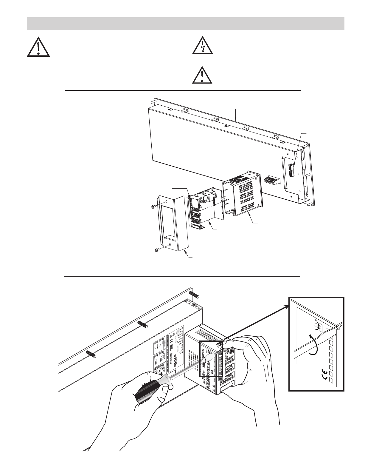
Installing the MPAX
Remove the MPAX case (plastic) from the rear of the
EPAX by removing the two screws and pulling off the
metal holding bracket. Install the MPAX into plastic case
by aligning the front connector of the MPAX with the hole
in the front of the plastic case. The module must be
oriented as shown with terminal #1 toward the top of the
EPAX case. Next, insert the MPAX case into the EPAX by
lightly pushing the connector of the MPAX into the
connector of the EPAX PC board. Place holding bracket
over the plastic case and install the two screws.
Installing the Labels
Each option card and the MPAX are shipped with a
connection label. These labels must be applied to the rear
of the EPAX in the positions shown in the drawing.
WARNING: Exposed line voltage exists on the MPAX main circuit
board and the option cards. DO NOT apply power to the
module OR load circuits until the module is properly installed
in the EPAX case.
NOTE: All module and option card labels must be installed as
shown for safety purposes.
EPAX
EPAX CONNECTOR
TERMINAL # 1
MPAX CASE
MPAX
HOLDING BRACKET
Figure 1, Installing an MPAX Module and Option Cards
Removing The MPAX Module
To remove the MPAX Module from the EPAX Display, first remove all
power and load circuits. Then insert a flat screwdriver blade (3/16" or
1
/4") into the narrow slot between the EPAX rear cover plate and
the module’s plastic cover as illustrated in Figure 2. Twist
the screwdriver in the direction shown to disengage the
internal connectors while firmly squeezing and
pulling back on the rear finger tabs (top and
bottom). Carefully slide the module
out of the EPAX case, keeping it
properly aligned with the
case opening.
Figure 2, Removing an MPAX Module
TWIST
SLOT
7 654 32
8
3

2.0 INSTALLING THE DISPLAY
2X
(123.3)
5X 4.85
(158.2 )
(170.8)
6.72
6.23
3.36
(85.4)
0.23 (5.9) DIA.
THRU, TYP.
(604.3 )
23.79
24.27 (616.5)
+.04
-.00
+1.01
-.00
+.03
-.00
+.76
-.00
EPAX DISPLAY INSTALLATION
The EPAX display is intended to be mounted
into a panel or enclosure. The display is provided
with a gasket to provide a water-tight seal. The
recommended minimum panel thickness for
NEMA 4/IP65 sealing is 0.060" (1.57 mm).
For panel mounting, prepare the panel
cut-out to the dimensions shown in
Figure 3. The supplied template may be
used to mark the cut-out and hole
locations on the panel. After the panel
cut-out has been deburred, slide the
panel gasket over the rear of the display
and onto the mounting studs. Insert the
display into the panel cut-out as
illustrated in Figure 4. Install 14 #
10-32 keps nuts (supplied) and tighten
evenly for uniform gasket compression.
Do not over-tighten the nuts.
By using additional mounting accessories,
the EPAX can be surface-wall mounted, suspended,
or bottom mounted. Separate installation instructions are
provided with the mounting accessories.
DIMENSIONS In inches (mm)
Figure 3, Panel Cut-out for the EPAX
Environment And Cleaning
The display should be installed in a location that does
not exceed the maximum operating temperature and
provides good air circulation. Placing the system near
devices that generate excessive heat should be avoided.
The bezel should be cleaned only with a soft cloth and
neutral soap product. Do NOT use solvents. Continuous
exposure to direct sunlight may accelerate the aging
process of the bezel.
FRONT
PANEL
MOUNTING
PANEL
GASKET
PANEL
MA2204X
E
CONNECTED TO
MUST BE
METAL PANEL
1
~~
85-250VAC
AC AC
50/60Hz
2 3 4 5 6 7
14VA
COMMUNICATION OPTION ANALOG OUT OPTION SETPOINT (SP) OPTION
SIGNAL INPUTS
!
VOLT/OHM
RS485 COMMUNICATION
CURRENT
12
OUTPUT
21
COMM
7
RST KEY
0-10V
ANALOG
- B(-)
ANALOG OUTPUT
+16
QUAD RELAY S.P.
20
RLY1
6
F2 KEY
PAXCDC10
PAXCDL10
PAXCDS20
5
F1 KEY
COMM
+EXCITATION
COMM
8 9
USER INPUTS
1
R
2
10 11
3
SEE LITERATURE FOR
JUMPER SELECTION
N/C
RED LION CONTROLS
YORK, PA. MADE IN U.S.A.
MODEL PAXD
CAUTION: DISCONNECT
ALL POWER BEFORE INSTALL-
ING OR REMOVING MODULE.
2
~
3 1
~
DSP KEY
AC AC
4
PAR KEY
85 - 250VAC
50/60Hz @ 5VA
RJ12
13
14
- A(+)
15
- COMM
- N/C
17
-
+18
-19
0-20mA
ANALOG
OUTPUT
22
23
24
25
RLY2
RLY3
COMM
RLY4
RELAYS RATED
3A @ 250VAC
(RESISTIVE LOAD)
8
COMM
!
MODEL EPAX
RED LION CONTROLS
YORK, PA.
MADE IN U.S.A.
MOUNTING STUDS AND NUTS
(14 PLACES)
CONNECT THIS STUD
TO A PROTECTIVE
EARTHING SYSTEM
!
CASE
VENT
HOLES
TWIST
SLOT
12
DISCONNECT ALL
3
456
CAUTION:
POWER BEFORE INSTALLING OR
REMOVING MODULE
7
89
MODEL LPAX
1011
RED LION CONTROLS
YORK, PA. MADE IN U.S.A.
TO REMOVE MODULE:
WHILE FIRMLY DEPRESSING REAR FINGER TABS (TOP & BOTTOM),
INSERT SCREWDRIVER BLADE (3/16" OR 1/4") INTO NARROW SLOT
(AT THE ARROW) AND TWIST IN THE DIRECTION SHOWN.
!
REAR COVER PLATE
OPENING
CAUTION
DISCONNECT
ALL POWER
BEFORE
MODULE
RETENTION
LATCH (TOP
AND BOTTOM)
MODULE RELEASE
FINGER TAB
(TOP & BOTTOM)
Figure 4, Installing The EPAX Into A Panel
4

3.0 WIRING AND PROGRAMMING THE DISPLAY
21
36
Note: Both the EPAX and the MPAX module require power. It is
recommended to connect the primary AC power to the EPAX terminal
block, then jumper to the MPAX module.
EPAX REAR VIEW
EPAX PROGRAMMING
The unit is a large display, designed to be remotely mounted. Therefore,
the unit does not have a programming keypad. Unit programming must be
accomplished by one of the following three methods:
8
RST KEY
COMM
F2 KEY
!
MODEL EPAX
RED LION CONTROLS
YORK, PA.
MADE IN U.S.A.
MPAX
MODULE
CAUTION:
ING OR REMOVING MODULE
ALL POWER BEFORE INSTALL-
M2967X
4576 123
DSP KEY
PAR KEY
F1 KEY
~
~
AC AC
85 - 250VAC
50/60Hz @ 5VA
DISCONNECT
RJ12
Optional Programming Remote (EPAXPGM0)
This optional programming remote
plugs into the EPAX through an
RJ12 connector and a 10 foot cable.
The buttons on the programming box
function the same as the PAX unit.
Simply program the EPAX exactly
as the PAX instructions indicate. The
programming box can be left
connected to the EPAX for future
programming changes or can be
disconnected and used to program
additional EPAX units.
RJ12 CONNECTOR ON BOTTOM OF UNIT
RJ12 FEMALE
PIN
1DSP KEY
2
3
4
5
6
NAME
PAR KEY
F1 KEY
F2 KEY
RST KEY
COMM
12 4
RJ12 CONNECTOR
ON BOTTOM OF UNIT
Rear Terminal Block
External normally open switches can be wired via the terminal block to allow
unit programming. A minimum of 3 switches would be required. Each
external switch must be wired between the key and the common terminal.
EPAX TERMINAL BLOCK
~
AC
85 - 250VAC
50/60Hz @ 5VA
~
AC
DSP KEY
PAR KEY
F1 KEY
67543
F2 KEY
RST KEY
8
COMM
Optional Serial Programming
5
Like all PAX units, you can purchase an RS232 or RS485 Comms Card and
program the unit via Windows® based software programs.
5

NEMA 4/IP65 LARGE DISPLAY ENCLOSURE & SHROUD FOR EPAX
LIGHT-WEIGHT ALUMINUM CONSTRUCTION
COMPLETELY SEALED FOR WASH-DOWN
MOUNTING CHANNELS FOR VERSATILE INSTALLATION
DESCRIPTION
The NEMA 4/IP65 Large Display Enclosure is designed to protect the EPAX
from dust and hose directed water, when properly installed. This light-weight
all aluminum unit utilizes welded seams and neoprene gaskets to meet NEMA
4/IP65 requirements. A textured, polyurethane coating protects against corrosion
Picture includes the EPAX, Nema Enclosure, and Shroud
and is scratch resistant. Figure 1 below shows the overall dimensions of the
Enclosure. The Display Enclosure with Mounting Channels weighs 9 pounds
(4.1 Kg).
DIMENSIONS In inches (mm) MOUNTING
21.00 (533.4)
1.25 (31.8)
27.50 (698.5)
10.00
(254)
.75
(19.1)
6.50*
(165.1)
7.11**
(180.6)
* Housing Only ** Overall Including Screwheads
Figure 1 Figure 3
Provided with the enclosure are two ¼-20 UNC x 1" hex
bolts, two ¼-20 UNC “strut nuts”, and two ¼" washers. The
“strut nuts” can be installed anywhere in the channel by
inserting them, spring side down, into the channels, then
rotating them 90 degrees clockwise until the notches engage
with the lips of the channel. The bolts and washers provided
allow mounting to surfaces ¼" to ½" thick (6.4 to 12.7 mm).
Use longer bolts for mounting to thicker surfaces. Bolts
fabricated from materials other than steel are not recommended.
1/4-20 UNC STEEL BOLT
WASHER
MOUNTING CHANNEL
STRUT NUT
TYPICAL INSTALLATIONS FOR NEMA 4/IP65 ENCLOSURE
Removing the rear panel of the enclosure allows access to the Display for
service. Either the rear panel or housing may be drilled to accept sealed conduit
fittings, liquid-tight cable fittings or other types of wiring connectors. The
enclosure may be attached to horizontal surfaces located above or below it,
using the mounting channels provided.
I-BEAM
ENCLOSURE
BASEMOUNT WITH WATERTIGHT
CABLE CONNECTOR ENTERING
THROUGH REAR PANEL.
SUSPENDED FROM CONDUIT
WITH SEALED FITTINGS.
(SHOWN WITH SHROUD).
Figure 2
6
BEAM MOUNT WITH SEALED
CONDUIT ENTERING FROM
RIGHT SIDE.

ASSEMBLY AND INSTALLATION PROCEDURE
1. Install the two mounting channels on the enclosure housing using
the four #8-32 screws provided and then insert the strut nuts
(provided). Invert enclosure if base mounting.
2. If the wiring is to be routed through the housing, make sure that
the mounting channels are oriented properly before drilling, so
the Display will be readable. Wiring is generally brought into the
right side of the housing or rear panel, closest to the terminals of
the MPAX module. Drill the proper size hole in the housing or
rear panel for the wiring connector or sealed conduit fitting and
attach the fitting(s)
3. Before installing the Display into the housing, be sure that the
mounting channels are oriented properly for the type of
installation planned. Place the gasket that is supplied with the
Display over the studs extending from the front panel of the
display.
4. If using the shroud, refer to the Shroud Installation Procedure.
Place the Display with gasket through the holes in the housing as
shown at right. Working back and forth across the stud pattern,
install the #10-32 keps nuts supplied with the Display on the
studs. Tighten firmly.
5. Mount the housing, using the strut nuts and steel ¼-20 UNC
bolts and washers, as shown in figure 4.
6. Connect the wires to the Display per the instructions included
with the personality board.
7. Remove the center section of the rear panel gasket. Apply the
gasket to the rear panel of the enclosure by inserting the #8-32
screws through the panel and into the holes in the gasket.
Position the panel on the housing, start all of the screws, then
firmly tighten them in a pattern working back and forth across
the rear panel.
1/4-20 x 1"
SCREW & WASHER
#8-32 SCREWS
TYP. 4
MOUNTING
CHANNEL
TYP. 2
EPAX
* Supplied with EPAX.
STRUT NUT
TYP. 2
#10-32
KEPS NUTS *
TYP. 14
Figure 4
#8-32 SCREWS
TYP. 16
REAR PANEL GASKET
HOUSING
FRONT PANEL GASKET *
REAR PANEL
DIMENSIONS FOR THE EPAX DISPLAY SHROUD
The optional EPAX Display Shroud enhances the readability of the
DIMENSIONS In inches (mm)
25.12 (637.9)
Displays that are installed in areas with high intensity overhead light
sources. The Shroud can be used with the EPAX Display in any
installation, (panel mount, NEMA 4/IP65 Enclosure, or Universal
Mounting Bracket). When properly assembled, the Shroud will not
affect the integrity of a NEMA 4/IP65 installation. The Shroud
weighs 1.0 pounds (0.45 Kg).
SHROUD INSTALLATION PROCEDURE
Installing The Shroud On An EPAX Display In A NEMA 4/IP65 Enclosure Or Panel
1. Place a gasket over the studs extending from the rear of the
front panel of the Display.
2. Orient the shroud as shown in Figure 6, and place it over the
display. The studs of the display should now be protruding
through the rear of the shroud.
3. Place the other gasket over the studs.
4. Install the unit into the panel or enclosure using the #10-32
keps nuts that are supplied with the Display. Tighten the nuts
firmly.
GASKET
SHROUD
Figure 5
3.65
(92.7)
7.60
(193)
PANEL OR NEMA 4 ENCLOSURE
#10-32
KEPS NUTS *
TYP. 14
EPAX
Nema 4/IP65 Shroud Installation
* Supplied with EPAX.
7
Figure 6
FRONT PANEL GASKET *

ORDERING INFORMATION
TYPE MODEL NO. DESCRIPTION PART NUMBERS
Display EPAX
Digital
Input
Module
Optional
Plug-In
Cards
Accessories
MPAX
PAXCDS
PAXCDC*
PAXCDL*
PAXUSB
PAXRTC*
PGM
SFCRD**
SFPAX** PC Configuration Software for Windows 95/98 on 3.5" disk (for MPAXCK00 and MPAXTM00 Modules)
ENC12
SHR
EN/SH
*Refer to “Selecting Your Display Components and Option Cards.”
**Available as a FREE download from the Red Lion website. www.redlion.net
6-Digit Extra Large Display for Digital MPAX Modules EPAX0600
Count/Rate Indicator Module, AC Powered MPAXI020
Count Indicator Module, AC Powered MPAXC020
Rate Indicator Module, AC Powered MPAXR020
Real-Time Clock Module, AC Powered MPAXCK00
Timer Module, AC Powered MPAXTM00
Dual Setpoint Relay Output Card PAXCDS10
Quad Setpoint Relay Output Card PAXCDS20
Quad Setpoint Sinking Open Collector Output Card PAXCDS30
Quad Setpoint Sourcing Open Collector Output Card PAXCDS40
RS485 Serial Communications Output Card with Terminal Block PAXCDC10
Extended RS485 Serial Communications Output Card with Dual RJ11 Connector PAXCDC1C
RS232 Serial Communications Output Card with Terminal Block PAXCDC20
Extended RS232 Serial Communications Output Card with 9 Pin D Connector PAXCDC2C
DeviceNet Communications Card PAXCDC30
Modbus Communications Card PAXCDC40
Extended Modbus Communications Card with Dual RJ11 Connector PAXCDC4C
Profibus-DP Communications Card PAXCDC50
Analog Output Card PAXCDL10
PAX USB Programming Card (Not included in PAX product UL E179259 file). PAXUSB00
Real-Time Clock Card (Replacement Only) PAXRTC00
Programming Remote for EPAX with 10 foot cable EPAXPGM0
Crimson 2 PC Configuration Software for Windows 98, ME, 2000 and XP (for MPAXI020 Module) SFCRD200
NEMA 4/IP65 Enclosure for EPAX ENC12000
Shroud for EPAX SHREPAX0
EPAX NEMA 4/IP65 Enclosure and Shroud EPAXENSH
SFPAX
TROUBLESHOOTING
For technical assistance, contact technical support.
LIMITED WARRANTY
The Company warrants the products it manufactures against defects in materials and workmanship for a
period limited to two years from the date of shipment, provided the products have been stored, handled,
installed, and used under proper conditions. The Company’s liability under this limited warranty shall
extend only to the repair or replacement of a defective product, at The Company’s option. The Company
disclaims all liability for any afrmation, promise or representation with respect to the products.
The customer agrees to hold Red Lion Controls harmless from, defend, and indemnify RLC against
damages, claims, and expenses arising out of subsequent sales of RLC products or products containing
components manufactured by RLC and based upon personal injuries, deaths, property damage, lost prots,
and other matters which Buyer, its employees, or sub-contractors are or may be to any extent liable,
including without limitation penalties imposed by the Consumer Product Safety Act (P.L. 92-573) and
liability imposed upon any person pursuant to the Magnuson-Moss Warranty Act (P.L. 93-637), as now in
effect or as amended hereafter.
No warranties expressed or implied are created with respect to The Company’s products except those
expressly contained herein. The Customer acknowledges the disclaimers and limitations contained herein
and relies on no other warranties or afrmations.
 Loading...