

Page 1
Tel +1 (717) 767-6511
Fax +1 (717) 764-0839
www.redlion.net
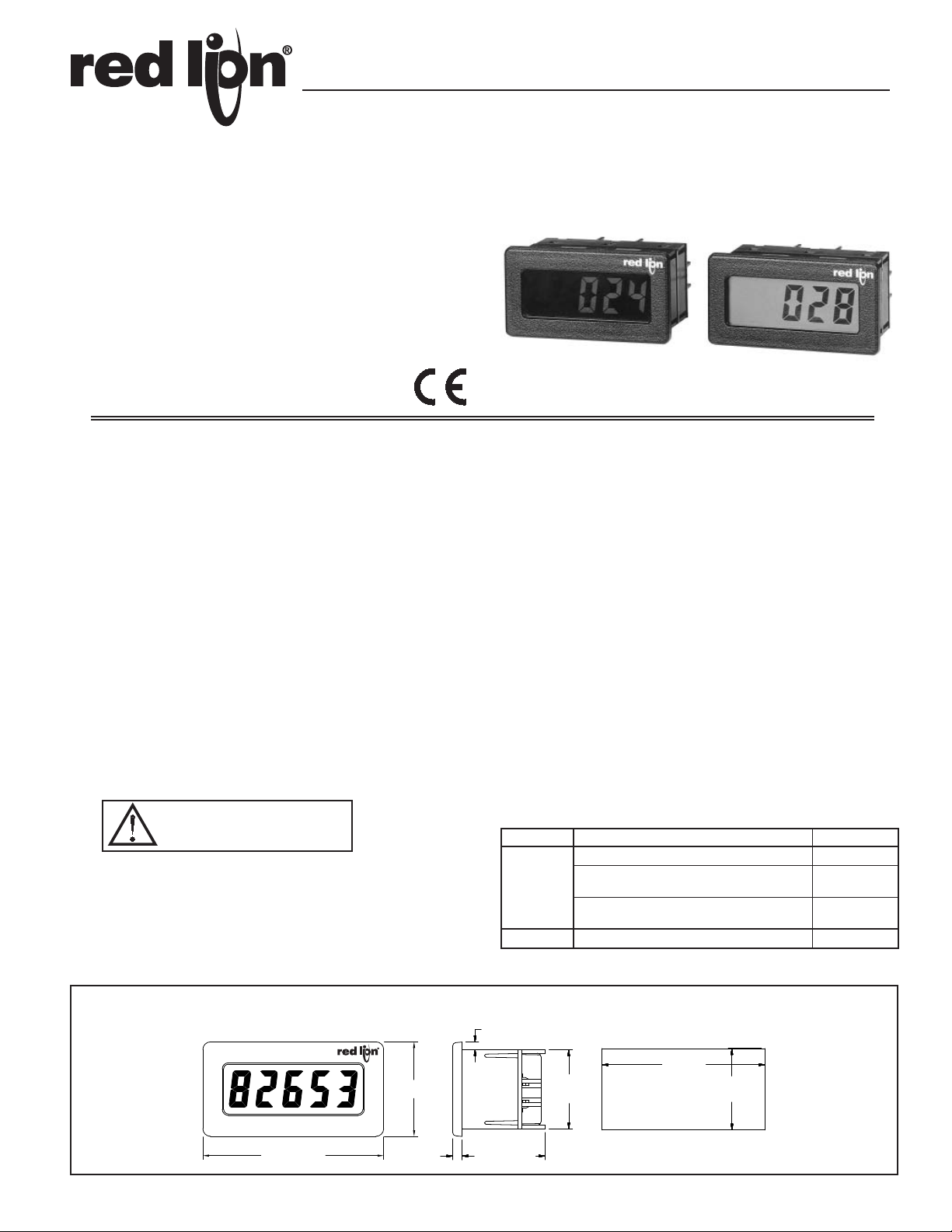
DITAK 8 - ADJUSTABLE TIMEBASE 5-DIGIT RATE INDICATOR
LCD, POSITIVE REFLECTIVE OR NEGATIVE TRANSMISSIVE
WITH YELLOW/GREEN OR RED BACKLIGHTING
0.6 INCH (15.2 mm) HIGH DIGITS
ADJUSTABLE TIMEBASE FROM 4 MSEC TO 63 SEC
INTERNAL LITHIUM BATTERY PROVIDES OVER 5 YEARS OF
CONTINUOUS OPERATION
NEMA 4X/IP65 SEALED FRONT PANEL BEZEL
ACCEPTS MAGNETIC OR LOGIC TYPE SIGNAL INPUTS
WIRE CONNECTIONS MADE VIA SCREW CLAMP TYPE
TERMINALS
Bulletin No. DT8-E
Drawing No. LP0555
Released 04/10
DESCRIPTION
The Ditak 8 is a self-powered rate indicator which features selectable
Timebase Increments by setting the appropriate DIP switches on the rear of the
unit. The internal 3.6 VDC lithium battery will operate continuously for at least
5 years. It has a 5-digit LCD display with 0.6 inch (15.2 mm) high digits. The
displays are available in positive image reflective (black digits, reflective
background) or negative image transmissive (illuminated digits, dark
background) with red or yellow/green backlighting. Backlight version units
require power from an external 9 to 28 VDC supply.
The unit is constructed of a lightweight, high impact plastic case with a clear
viewing window. The sealed front panel meets NEMA 4X/IP65 specifications
for wash-down and/or dusty environments, when properly installed.
The optional Micro Line/Sensor Power Supply (MLPS1000) is designed to
attach to the rear of an installed Ditak 8. The optional supply can be powered
from 85 to 250 VAC, and can provide power for the backlighting of a unit and
most sensors.
SAFETY SUMMARY
All safety related regulations, local codes and instructions that appear in the
manual or on equipment must be observed to ensure personal safety and to
prevent damage to either the instrument or equipment connected to it. If
equipment is used in a manner not specified by the manufacturer, the protection
provided by the equipment may be impaired.
CAUTION: Risk of Danger.
Read complete instructions prior to
installation and operation of the unit.
SPECIFICATIONS
1. DISPLAY: 5-Digit LCD, 0.6" (15.2 mm) high digits.
2. POWER SOURCE: Internal 3.6 V lithium battery provides over 5 years of
continuous service (battery life is dependent upon usage).
3. BACKLIGHT POWER REQUIREMENTS: 9 to 28 VDC @ 35 mA.
Above 26 VDC, derate operating temperature to 50 °C. Must use the MLPS1
or an NEC Class 2 or Limited Power Source (LPS) rated power supply.
4. SIGNAL INPUT: 0 to 10 KHz from a magnetic or bi-polar output (with a
50% duty cycle). Min. input sensitivity is 0.9 V. Max. input = 28 VDC.
5. TIMEBASE: Adjustable in 1/256 sec (3.906 msec) increments via DIP
switches located at the rear of the unit. Timebase ranges from 3.906 msec to
63.99 sec; 0.01% ±1 digit accuracy.
6. ENVIRONMENTAL CONDITIONS: Operating Temperature: 0 to 60 °C
(Above 50 °C derate backlight operating voltage to 26 VDC max.)
Storage Temperature: -40 to 80 °C
Operating and Storage Humidity: 85% max. (non-condensing) from 0 °C
to 60 °C.
Vibration According to IEC 68-2-6: Operational 5 to 500 Hz, in X, Y, Z
direction for 1.5 hours, 5 g’s.
Shock According to IEC 68-2-27: Operational 30 g’ s, 1 1 msec in 3 directions.
Altitude: Up to 2000 meters
7. CONSTRUCTION: High impact plastic case with clear viewing window
(Panel gasket and mounting clip included). Installation Category I, Pollution
Degree 2.
ORDERING INFORMATION
MODEL NO. DESCRIPTION PART NUMBER
Adjustable Timebase Tachometer DT800000
DT8
MLPS Micro Line Sensor/Power Supply MLPS1000
Adjustable Timebase Tachometer with Yellow/
Green Backlighting
Adjustable Timebase Tachometer with Red
Backlighting
DT800010
DT800020
DIMENSIONS In inches (mm)
2.95 (74.9)
1.54 (39.1)
0.15
(3.8)
Note: Recommended minimum clearance (behind the panel) for
mounting clip installation is 2.15" (54.6) H x 3.0" (76.2) W.
0.13 (3.2)
+.025
2.68
-.000
+.6
(68 )
1.38 (35.1)
1.29
(32.8)
-.0
1.30
+.6
(33 )
-.0
+.024
-.000
1
Page 2
SHIELD
RED
BLACK
COMM
INPUT
MACHINE
FRAME
MP62TA
AC
V
AUDIO OR A.C.
TACH. GEN.
SIGNAL SOURCE
INPUT
COMM
OR INVERTER
TRANSFORMER FOR
HIGH VOLTAGE
STEP-DOWN ISOLATION
AC
V
TO HIGH
POWER LINE
VOLTAGE
+V
INPUT
COMM
TTL or CMOS
INPUT
TRANSISTOR INPUT
NPN OPEN COLLECTOR
4.7K
+V
PNP OPEN COLLECTOR
TRANSISTOR INPUT
4.7K
COMMON
+V
SPECIFICATIONS (Cont'd)
8. CERTIFICA TIONS AND COMPLIANCES:
SAFETY
IEC 1010-1, EN 61010-1: Safety requirements for electrical equipment for
measurement, control, and laboratory use, Part 1.
IP65 Enclosure rating (Face only), IEC 529
Type 4X Enclosure rating (Face only), UL50
ELECTROMAGNETIC COMPATIBILITY
Emissions and Immunity to EN 61326: 2006: Electrical Equipment for
Measurement, Control and Laboratory use.
Immunity to Industrial Locations:
Electrostatic discharge EN 61000-4-2 Criterion A
4 kV contact discharge
8 kV air discharge
Electromagnetic RF fields EN 61000-4-3 Criterion A
10 V/m (80 MHz to 1 GHz)
3 V/m (1.4 GHz to 2 GHz)
1 V/m (2 GHz to 2.7 GHz)
Fast transients (burst) EN 61000-4-4 Criterion A
power 2 kV
I/O signal 1 kV
Surge EN 61000-4-5 Criterion A
power 1 kV L to L, 2 kV L to G
RF conducted interference EN 61000-4-6 Criterion A
3 V/rms
Power frequency magnetic fields EN 61000-4-8 Criterion A
30 A/m
AC power EN 61000-4-11 Criterion A
Voltage dip 0% during 1 cycle
40% during 10/12 cycle
70% during 25/30 cycle
Short interruptions Criterion B
0% during 250/300 cycles
Emissions:
Emissions EN 55011 Class B
Notes:
1. Criterion A: Normal operation within specified limits.
2. Criterion B: Temporary loss of performance from which the unit self-
recovers.
Refer to the EMC Installation Guidelines section of this bulletin for additional
information.
9. WEIGHT: 3.4 oz (96.4 g)
EMC INSTALLATION GUIDELINES
Although this unit is designed with a high degree of immunity to
ElectroMagnetic Interference (EMI), proper installation and wiring methods
must be followed to ensure compatibility in each application. The type of the
electrical noise, source or coupling method into the unit may be different for
various installations. In extremely high EMI environments, additional measures
may be needed. Cable length, routing and shield termination are very important
and can mean the difference between a successful or a troublesome installation.
Listed below are some EMC guidelines for successful installation in an
industrial environment.
1. Use shielded (screened) cables for all Signal and Control inputs. The shield
(screen) pigtail connection should be made as short as possible. The
connection point for the shield depends somewhat upon the application.
Listed below are the recommended methods of connecting the shield, in order
of their effectiveness.
a. Connect the shield only at the panel where the unit is mounted to earth
ground (protective earth).
b. Connect the shield to earth ground at both ends of the cable, usually when
the noise source frequency is above 1 MHz.
c. Connect the shield to common of the unit and leave the other end of the
shield unconnected and insulated from earth ground.
2. Never run Signal or Control cables in the same conduit or raceway with AC
power lines, conductors feeding motors, solenoids, SCR controls, and
heaters, etc. The cables should be run in metal conduit that is properly
grounded. This is especially useful in applications where cable runs are long
and portable two-way radios are used in close proximity or if the installation
is near a commercial radio transmitter.
3. Signal or Control cables within an enclosure should be routed as far away as
possible from contactors, control relays, transformers, and other noisy
components.
4. In extremely high EMI environments, the use of external EMI suppression
devices, such as ferrite suppression cores, is effective. Install them on Signal
and Control cables as close to the unit as possible. Loop the cable through the
core several times or use multiple cores on each cable for additional
protection. Install line filters on the power input cable to the unit to suppress
power line interference. Install them near the power entry point of the
enclosure. The following EMI suppression devices (or equivalent) are
recommended:
Ferrite Suppression Cores for signal and control cables:
Fair-Rite # 0443167251 (RLC #FCOR0000)
TDK # ZCAT3035-1330A
Steward #28B2029-0A0
Line Filters for input power cables:
Schaffner # FN610-1/07 (RLC #LFIL0000)
Schaffner # FN670-1.8/07
Corcom #1VR3
Note: Reference manufacturer’s instructions when installing a line filter.
5. Long cable runs are more susceptible to EMI pickup than short cable runs.
Therefore, keep cable runs as short as possible.
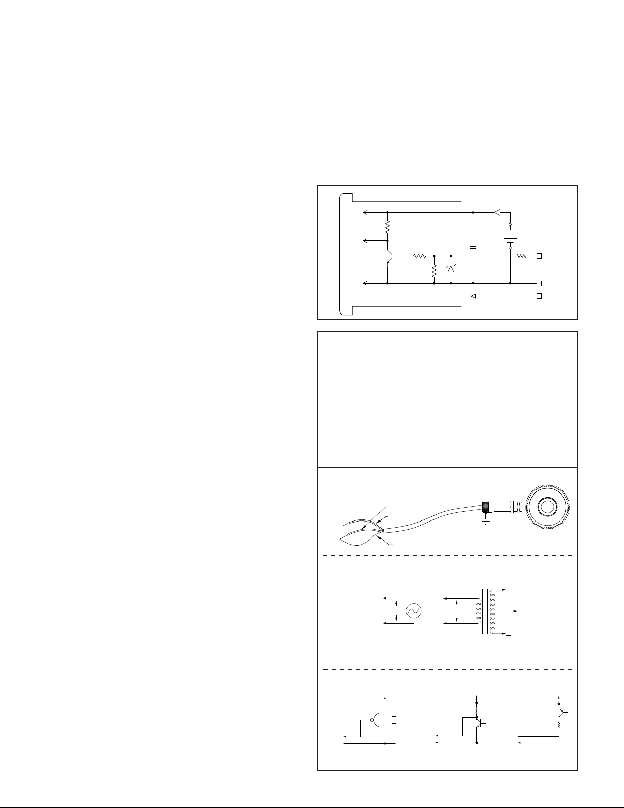
BLOCK DIAGRAM
3V
SIGNAL
GND
220K
100K
100K
3.6V
OPTIONAL
BACKLIGHTING
.1µF
3.6V
LITHIUM
6.2K
3
INP
GND
1
2
V+
WIRING CONNECTIONS
The electrical connections are made via rear screw-clamp terminals
located on the back of the unit. All conductors should meet voltage and
current ratings for each terminal. Also cabling should conform to appropriate
standards of good installation, local codes and regulations. It is recommended
that power supplied to the unit (AC or DC) be protected by a fuse or circuit
breaker. When wiring the unit, use the label to identify the wire position with
the proper function. Strip the wire, leaving approximately 1/4" bare wire
exposed (stranded wires should be tinned with solder). Insert the wire into
the screw-clamp terminal and tighten the screw until the wire is clamped
tightly. Each terminal can accept up to two #14 AWG wires.
The backlighting for a backlight version unit is powered between T erminal
2 (V+) and Terminal 1 (GND).
Variable Frequency AC Inputs, Signal Source Powered
Variable Frequency AC Inputs, Signal Source Powered
Minimum VAC for operation is 0.9 V peak.
Logic Pulse Inputs From Other Circuits & Sensors
2
Page 3

REAR PANEL DIP SWITCHES
1248163264
128
256
512
1024
2048
4096
8192
TIMEBASE INCREMENTS
V+ 2
3 INP
1 GND
SWB
81
ON
SWA
DT8
16
WARNING: LITHIUM BATTERY
MAY EXPLODE IF INCINERATED
MADE IN U.S.A.
YORK, PA.
When viewing the Ditak 8 from the rear, there are two banks of DIP switches
located along the top edge of the PC board. The bank of eight switches to the
left is labeled SWA and the bank of six switches to the right is labeled SWB. All
of the switches are used to select the desired Timebase.
The Timebase increment total is computed according to the following formula:
TIMEBASE INCREMENT TOTAL (TBIT) =
DR x 15,361
RPM x PPR
WHERE:
DR = Desired Reading
RPM = Revolutions Per Minute
PPR = Pulses Per Revolution
Example: Find the appropriate Timebase DIP switch setting for desired
parameters.
Desired Readout (DR) = 2500
Revolutions Per Minute (RPM) = 1250
Pulses Per Revolution (PPR) = 50
WARNING: Lithium battery may explode if incinerated.
TIMEBASE SELECTION
The Ditak 8 has a Timebase selection range from 3.906 msec to 63.99 sec.
SWA 1 is set to the “ON” position for the minimum Timebase setting. SWA 1
through SWB 6 are set to the “ON” position for the maximum Timebase setting.
A specific Timebase setting is achieved by adding the appropriate individual
Timebase increments.
TIMEBASE
SWITCH
SWA 1 1 SWB 1 256
SWA 2 2 SWB 2 512
SWA 3 4 SWB 3 1024
SWA 4 8 SWB 4 2048
SWA 5 16 SWB 5 4096
SWA 6 32 SWB 6 8192
SWA 7 64
SWA 8 128
INCREMENTS
SWITCH
TIMEBASE
INCREMENTS
TIMEBASE INCREMENT TOTAL (TBIT) =
2500 x 15,361
1250 x 50
TBIT = 614.44
TBIT = 614
{round to the nearest whole number}
TBIT = 614
DIP SWB 2 - 512
DIP SWA 7 - 64
DIP SWA 6 - 32
DIP SWA 3 - 4
DIP SWA 2 - 2
102 - Needed
38 - Needed
6 - Needed
2 - Needed
0 - Needed
Note: If no timebase switches are turned on, the Ditak 8 will default to 3.906
msec timebase.
DIP switches SWA 2, 3, 6, 7, and SWB 2 are all set to the “ON” position for
a Timebase Increment Total of 614. If it is desired to know what the
approximate Timebase is in seconds, use the following formula:
TBIT x 0.003906 = Time in seconds
614 x 0.003906 = 2.398 sec.
TYPICAL APPLICATION
CONVEYOR BELT SPEED INDICATOR
It is desired to display the rate of a conveyor belt used to carry PC Boards through an infrared soldering chamber that is variable from 0 to 10 feet per minute.
The rate must be adjusted depending on the size of the boards being soldered. The display of the rate indicator must read in feet per minute. The shaft of the variable
speed motor contains a keyway. A speed of 100 RPM will produce a belt speed of 10 ft/min. A proximity sensor is used to monitor the speed of the shaft. The Ditak
8 can be used to display the belt speed in this application. The output signal of the sensor is connected to the Ditak 8 Terminal 3 (INP). The sensor common and
shield are connected to the Ditak 8 Terminal 1 (GND). The Timebase setting is to be determined by using the formula.
TIMEBASE INCREMENT TOTAL (TBIT) =
DR x 15,361
RPM x PPR
10 x 15,361
=
100 x 1
Desired Reading = 10
MAX RPM Of Shaft = 100
Pulses Per Revolution = 1
3
TBIT = 1536.1
TBIT = 1536
TBIT = 1536
DIP SWB 3 - 1024
DIP SWB 2 - 512
{round to the nearest whole number}
512 - Needed
0 - Needed
Page 4

INSTALLATION ENVIRONMENT
EXISTING
PANEL
0.05" TO 0.20"
(1.3 TO 5.1mm)
THICK
GASKET
0.093"
(2.4 mm)
THICK
BEZEL
MOUNTING
CLIP
NUT
FASTENER
MOUNTING
SCREW
LATCHING
FEATURE
LATCHING
FEATURE
The unit should be installed in a location that does not exceed the
maximum operating temperature and provides good air circulation.Placing
the unit near devices that generate excessive heat should be avoided. The
bezel should be cleaned only with a soft cloth and neutral soap product. Do
NOT use solvents.Continuous exposure to direct sunlight may accelerate the
aging process of the bezel.
INSTALLATION
The Ditak 8 meets NEMA4X/IP65 requirements for indoor use, when
properly installed. The units are intended to be mounted into an enclosed
panel. A sponge rubber gasket, mounting clip, two screws, and nut fasteners
are provided to install and seal the unit in the panel cut-out.
The following procedure assures proper installation:
1. Cut panel opening to specified dimensions. Remove burrs and clean panel
opening.
2. Slide the panel gasket over the rear of the unit to the back of the bezel.
3. Slide nut fastener into slot on mounting clip and then insert mounting screw
through nut on both sides of mounting clip. Tip of mounting screw should
NOTproject through hole on clip.
4. Install Ditak unit through panel cut-out.
5. Slide mounting clip over rear of unit until clip is against back of panel. The
mounting clip and Ditak housing have a latching feature to hold the unit in
place until tightened.
Note: Hold the Ditak front bezel in place when sliding the mounting clip
into position.
6. Alternately tighten each mounting screw to ensure uniform gasket pressure.
Visually inspect the gasket for proper seal. The gasket should be
compressed approximately 75 to 80% of its original thickness.
7. If the gasket is not adequately compressed and the mounting screws cannot
be tightened any further, loosen mounting screws and insure that the clip is
latched as close as possible to the panel.
8. Repeat step #6 for tightening the mounting screws.
TROUBLESHOOTING
For further technical assistance, contact technical support at the appropriate company numbers listed.
The Company warrants the products it manufactures against defects in materials and
workmanship for a period limited to two years from the date of shipment, provided the products
have been stored, handled, installed, and used under proper conditions. The Company’s liability
under this limited warranty shall extend only to the repair or replacement of a defective product, at
The Company’s option. The Company disclaims all liability for any affirmation, promise or
representation with respect to the products.
The customer agrees to hold Red Lion Controls harmless from, defend, and indemnify RLC
against damages, claims, and expenses arising out of subsequent sales of RLC products or products
containing components manufactured by RLC and based upon personal injuries, deaths, property
damage, lost profits, and other matters which Buyer, its employees, or sub-contractors are or may be
to any extent liable, including without limitation penalties imposed by the Consumer Product Safety
Act (P.L. 92-573) and liability imposed upon any person pursuant to the Magnuson-Moss Warranty
Act (P.L. 93-637), as now in effect or as amended hereafter.
No warranties expressed or implied are created with respect to The Company’s products except
those expressly contained herein. The Customer acknowledges the disclaimers and limitations
contained herein and relies on no other warranties or affirmations.
LIMITED WARRANTY
Red Lion Controls
Headquarters
20 Willow Springs Circle
York PA 17406
Tel +1 (717) 767-6511
Fax +1 (717) 764-0839
Red Lion Controls
NL - 3821 AD Amersfoort
Tel +31 (0) 334 723 225
Fax +31 (0) 334 893 793
Europe
Printerweg 10
Red Lion Controls
India
54, Vishvas Tenement
GST Road, New Ranip,
Ahmedabad-382480 Gujarat, India
Tel +91 987 954 0503
Fax +91 79 275 31 350
4
Red Lion Controls
China
Unit 101, XinAn Plaza
Building 13, No.99 Tianzhou Road
ShangHai, P.R. China 200223
Tel +86 21 6113-3688
Fax +86 21 6113-3683
 Loading...