

Page 1
Tel +1 (717) 767-6511
PROCESS CONTROL EQUIPMENT
Fax +1 (717) 764-0839
www.redlion.net
DUAL LOOP CONTROLLER
U
R
C
US LISTED
L
3RSD
Bulletin No. DLC-J
Drawing No. LP0495
Released 09/16
MODULAR BUILDING BLOCK FOR MULTI-ZONE PROCESS CONTROL
TWO INDEPENDENT PID CONTROL LOOPS
PID CONTROL WITH REDUCED OVERSHOOT
UNIVERSAL INPUTS ACCEPT TC, RTD, 0-10 V AND 0/4-20 mA SIGNALS
TWO DC ANALOG OUTPUTS (OPTIONAL)
WINDOWS
RS485 MODBUS™ PROTOCOL
CHANNEL B CAN BE ASSIGNED AS A SECOND ANALOG INPUT TO
®
CONFIGURATION SOFTWARE
CHANNEL A FOR REMOTE SETPOINT OPERATION
SETPOINT CONTROLLER OPTION FOR TIME VS. TEMP./PROCESS
(RAMP/SOAK) AND SPECIAL BATCH/RECIPE APPLICATIONS
SQUARE ROOT EXTRACTION FOR FLOW SENSOR APPLICATIONS
GENERAL DESCRIPTION
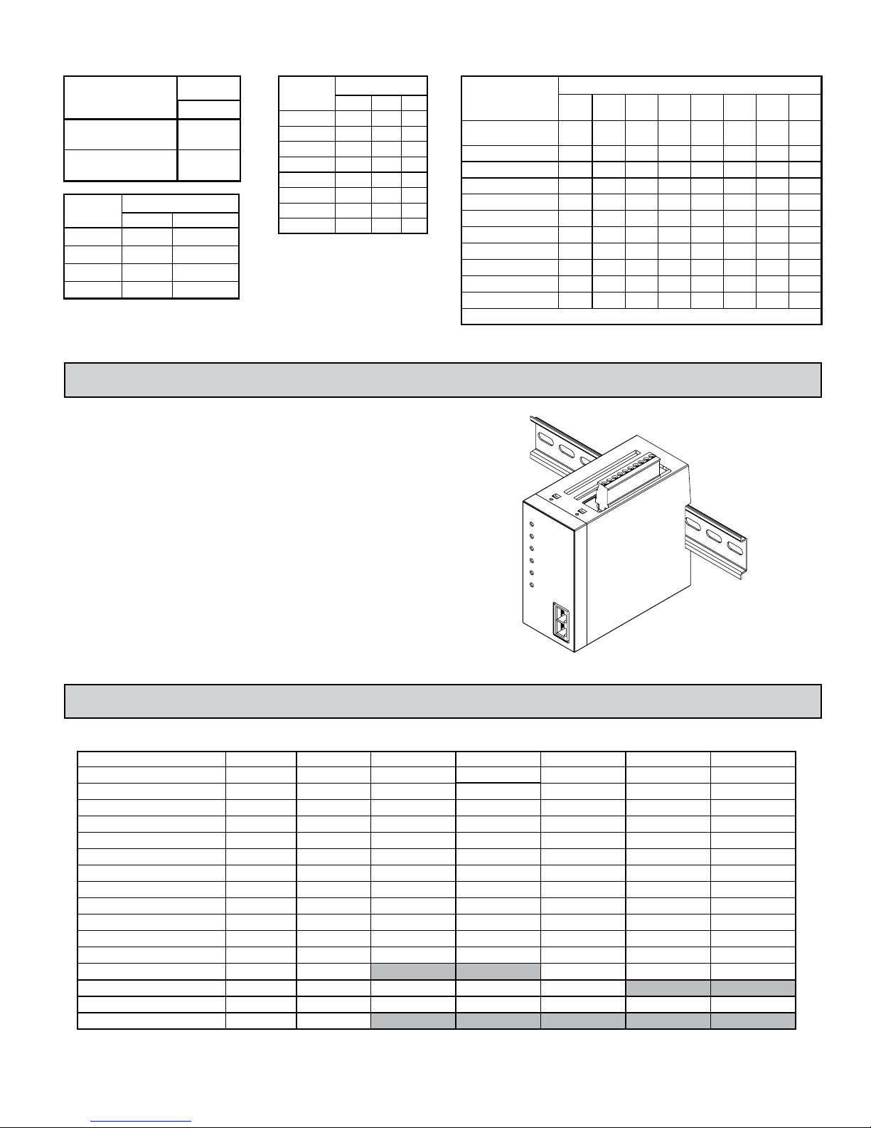
The Model DLC, Dual Loop Controller, is a full featured, DIN rail mounted,
dual input PID controller. The DLC is designed as a modular building block for
multi-zone process control applications. The controller has two independent
“A” & “B” input channels. Each channel’s input can be configured to accept a
wide range of thermocouple, RTD, 0-10 V, 0/4-20 mA, or resistive signals. Each
channel can also be configured to extract the square root of the input in both
process voltage or process current modes for applications such as flow
measurement using a differential flow sensor.
Channel B can be assigned as a Remote Setpoint for Channel A. The two
time-proportioning or DC Analog outputs can be programmed to control two
independent processes. The two alarms per channel can be configured for
various alarm modes, or provide a secondary control output for heat/cool
applications.
The control and alarm outputs are N channel open drain MOSFETs capable
of switching up to 1 Amp DC. For applications requiring larger loads or A/C
loads, several DIN rail mount relays are available.
The controller operates in the PID Control Mode for both heating and
cooling, with on-demand auto-tune, that establishes the tuning constants. The
PID tuning constants may be fine-tuned through the serial interface. The
controller employs a unique overshoot suppression feature, which allows the
quickest response without excessive overshoot. The controller can be transferred
to operate in the Manual Mode, providing the operator with direct control of the
output, or the On/Off Control Mode with adjustable hysteresis.
The controller’s high density packaging and DIN rail mounting saves time
and panel space. The controller snaps easily onto standard top hat (T) profile
DIN rails.
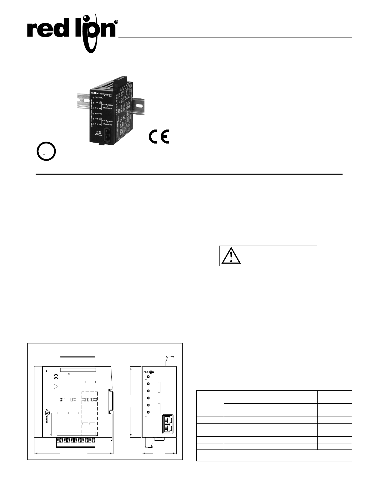
DIMENSIONS In inches (mm)
TBA
ต
POWER: (FULL LOAD)
AC 24V ±10%, 50/60 Hz, 15VA
DC 18-36V, 13W
!
RTD
FACTORY
JUMPER
SETTINGS
JUMPERS
CH B CH A
INPUTS
INPUT COMMON
3RSD
EQUIPMENT
CONTROL
PROCESS
TBB
12
1ต32ต4 6
OUTPUT COMMON
DC- / (AC)
DC+ / (AC)
+24VDC OUT
20mA
20mA
RTD
10V
10V
INPUTS
0-10V, 0-20mA
INPUT COMMON
TC+ OR RTD
TC+ OR RTD
RTD EXC.
RTD EXC.
435
4.47 (114)
5
OP1
AL178OP1
CH A CH B
OUTPUTS
DEFAULT SERIAL SETTING
0-10V, 0-20mA
6
789
AL2/OP2
OUTPUTS
V1+
V1-
I1+
ANALOG OUTPUT 1
0-10V, 0-20mA
OUT +
OUT -
AL1
V2+
I1-
0-10V, 0-20mA
OUT +
109
AL2/OP2
V2-
I2+
ANALOG OUTPUT 2
OUT -
1110
MODEL DLC
YORK, PA. MADE IN U.S.A.
RED LION CONTROLS
I2-
OPTIONAL
4.02
(102)
ALL FLASHING = CHECKSUM ERROR
PWR/COMM.
CH A OP
CH A ALM
AUTOTUNE
CH B OP
CH B ALM
MODBUS
PROTOCOL
RED LION CONTROLS
MODEL DLC
BOTH FLASHING
INPUT ERROR
BOTH FLASHING
INPUT ERROR
RS485
1.97
(50)
=
=
SAFETY SUMMARY
All safety related regulations, local codes and instructions that appear in the
manual or on equipment must be observed to ensure personal safety and to
prevent damage to either the instrument or equipment connected to it. If
equipment is used in a manner not specified by the manufacturer, the protection
provided by the equipment may be impaired.
Do not use the controller to directly command motors, valves, or other
actuators not equipped with safeguards. To do so can be potentially harmful to
persons or equipment in the event of a fault to the controller. An independent
and redundant temperature limit indicator with alarm outputs is strongly
recommended.
CAUTION: Risk of Danger.
Read complete instructions prior to
installation and operation of the unit.
ALARMS
The DLC’s two solid-state alarms can be configured independently for
absolute high or low acting with balanced or unbalanced hysteresis. They can
also be configured for deviation and band alarm. In these modes, the alarm
trigger values track the setpoint value. Adjustable alarm trip delays can be used
for delaying output response. The alarms can be programmed for Automatic or
Latching operation. Latched alarms must be reset with a serial command. A
standby feature suppresses the alarm during power-up until the temperature
stabilizes outside the alarm region. The outputs can also be manually controlled
with Modbus register or coil commands.
SETPOINT CONTROLLER OPTION
The Setpoint Controller option is suitable for time vs. temperature/process
control applications. The controller allows a profile of up to 20 ramp/soak
segments. Profile conformity is assured by using the Error Band Mode and
Error Band parameter. The Profile Cycle Count allows the profile to run
continuously or a fixed number of cycles. Power-on options automatically stop,
abort, start, resume, or pause a running profile.
ORDERING INFORMATION
MODEL NO. DESCRIPTION PART NUMBERS
Dual Loop Controller DLC00001
DLC
CBPRO Programming Interface Cable CBPRO007
CBJ Cable RJ11 to RJ11 (6 inch jumper) CBJ11BD5
DRR RJ11 to Terminal Adapter DRRJ11T6
See our RSRLYB, RLY6, and RLY7 literature for details on DIN rail
mountable relays.
Dual Loop Controller w/ 2 Analog Outputs DLC01001
Dual Setpoint Controller w/ 2 Analog Outputs DLC11001
SF PC Configuration Software for Windows SFDLC
RS485 to RJ11 Cable CBLRLC00
1
Page 2
COMMUNICATIONS
The RS485 serial communications allows the DLC to be multi-dropped, with
Baud rates up to 38400. The CBPRO007 programming cable converts the
RS232 port of a PC to RS485 and is terminated with an RJ11 connector. The
bi-directional capability of the CBPRO007 allows it to be used as a permanent
interface cable as well as a programming cable.
SOFTWARE
The DLC is programmed with Windows® based SFDLC software. The
software allows configuration and storage of DLC program files, as well as
calibration. Additionally, all setup and control parameters can be interrogated
and modified through MODBUS™ register and coil commands.
ANALOG OUTPUT OPTION
The optional dual DC Analog Output (10 V or 20 mA) can be independently
configured and scaled for control or re-transmission purposes. These outputs can
be assigned to separate channels, or both outputs can be assigned to the same
channel. Programmable output update time reduces valve or actuator activity.
SPECIFICATIONS
1. POWER:
18 to 36 VDC, 13 W (4 W if +24 VDC Output excitation is unused)
24 VAC, ±10% 50/60 Hz, 15 VA (7 VA if +24 VDC Output excitation is unused)
Must use a Class 2 or SELV rated power supply.
2. +24 VDC OUTPUT POWER: 24 VDC, +15%, -5%, 200 mA max
3. MEMORY: Non-volatile memory retains all programmable parameters.
4. INPUT:
Sample Time: 100 msec (9.5 Hz)
Failed Sensor Response: Open or shorted (RTD only) sensor coils
indication, error code returned in Process Value
Common Mode Rejection: >110 dB, 50/60 Hz
Normal Mode Rejection: >40 dB, 50/60 Hz
Temperature Coefficient: 0.013%/°C
Overvoltage: 50 VDC max
Step Response Time: 300 msec typ., 400 msec max
5. THERMOCOUPLE INPUTS:
Types: T, E, J, K, R, S, B, N, C, linear mV
Input Impedance: 20 MΩ
Lead Resistance Effect: 0.25 µV/Ω
Cold Junction Compensation: Less than ±1°C typical (±1.5°C max) over
0 to 50°C ambient temperature range or less than ±1.5°C typical (2°C
max) over -20 to 65°C maximum ambient temperature range.
Resolution: 1° or 0.1° for all types except linear mV (0.1 or 0.01 mV)
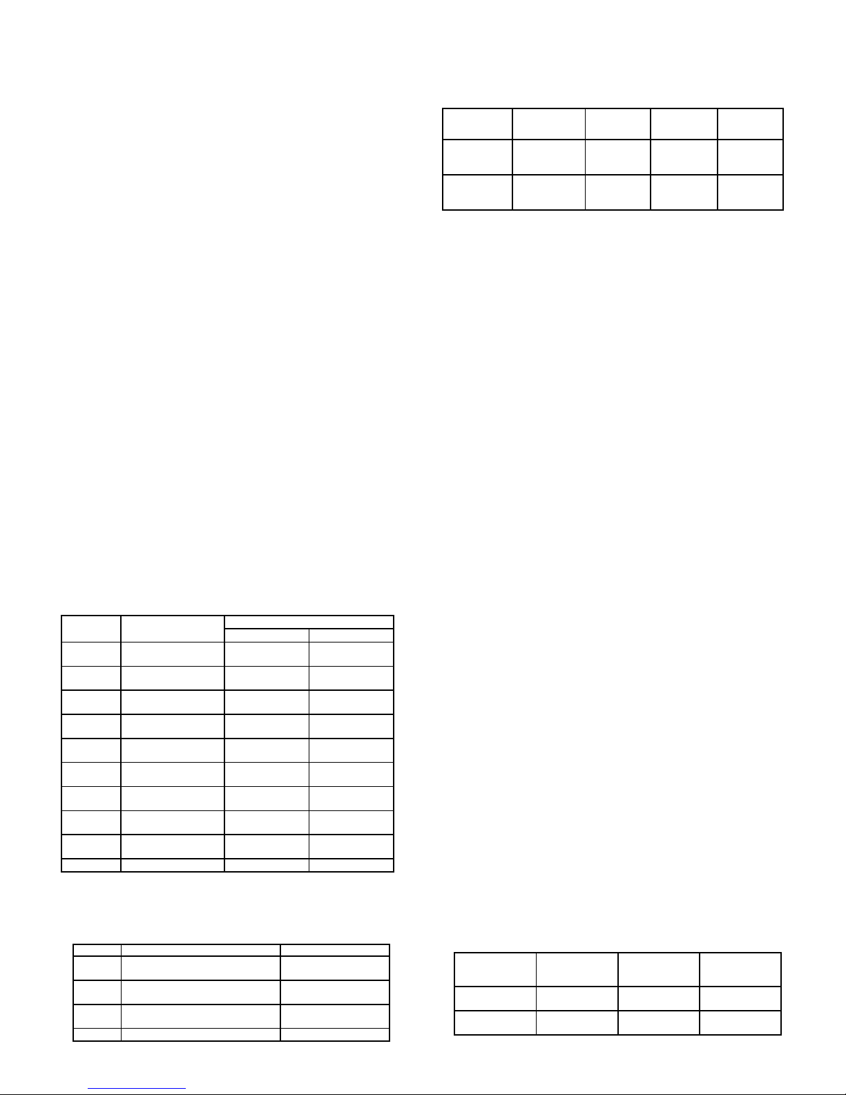
TYPE
T
E
J
K
R
S
B
N
C
W5/W6
mV -5 mV to 56 mV N/A N/A
MEASUREMENT
RANGE
-200 to +400°C
-328 to +752°F
-200 to +750°C
-328 to +1382°F
-200 to +760°C
-328 to +1400°F
-200 to +1250°C
-328 to +2282°F
0 to +1768°C
+32 to +3214°F
0 to +1768°C
+32 to +3214°F
+149 to +1820°C
+300 to +3308°F
-200 to +1300°C
-328 to +2372°F
0 to +2315°C
+32 to +4199°F
No Standard
No Standard
No Standard No Standard
No Standard No Standard
6. RTD INPUTS:
Type: 2 or 3 wire
Excitation: 150 µA
Lead Resistance: 15 Ω max
Resolution: 1 or 0.1° for all types
TYPE INPUT TYPE RANGE
385 100 Ω platinum, Alpha = .00385
392 100 Ω platinum, Alpha = .003919
672 120 Ω nickel, Alpha = .00672
ohms Linear Resistance 0 to 320 Ω
WIRE COLOR
ANSI BS 1843
(+) Blue
(-) Red
(+) Violet
(-) Red
(+) White
(-) Red
(+) Yellow
(-) Red
(+) Orange
(-) Red
(+) Orange
-200 to +600°C
-328 to +1100°F
-200 to +600°C
-328 to +1100°F
-80 to +215°C
-112 to +419°F
(+) White
(-) Blue
(+) Brown
(-) Blue
(+) Yellow
(-) Blue
(+) Brown
(-) Blue
(+) White
(-) Blue
(+) White
(-) Blue
(-) Blue
7. TEMPERATURE INDICATION ACCURACY: ± (0.3% of span, +1°C).
Includes NIST conformity, cold junction effect, A/D conversion errors,
temperature coefficient and linearization conformity at 23 °C after 20 minute
warm up.
8. PROCESS INPUT:
INPUT RANGE
10 VDC
(-1 to 11)
20 mA DC
(-2 to 22)
ACCURACY *
(18 to 28°C)
(10 to 75% RH)
0.10% of
reading
+0.02 V
0.10% of
reading
+0.03 mA
IMPEDANCE
1 MΩ 50 V 1 mV
10 Ω 100 mA 1 µA
MAX
CONTINUOUS
OVERLOAD
RESOLUTION
* Accuracies are expressed as ± percentages after 20 minute warm-up.
9. ISOLATION LEVEL: 500 VAC @ 50/60 Hz, for one minute (50 V
working) between the following groups:
Ch A Input
Ch B Input
Control and Alarm Outputs
RS485/Analog Output
1
Power Supply
Note:
1
RS485 and Analog Outputs are not internally isolated. Their commons
must not be connected together externally for proper unit function (i.e.,
earth ground).
10. SERIAL COMMUNICATIONS:
Type: RS485; RTU and ASCII MODBUS modes
Baud: 300, 600, 1200, 2400, 4800, 9600, 19200, and 38400
Format: 7/8 bits, odd, even, and no parity
Transmit Delay: Programmable: See Transmit Delay explanation.
Transmit Enable (TXEN): (primarily for 20 mA loop converter) open
collector VOH = 10 VDC max, VOL = 0.5 VDC @ 5 mA max current limit
11. A/D CONVERTER: 16 bit resolution
12. CONTROL AND ALARM OUTPUTS:
Type: Non-isolated switched DC, N Channel open drain MOSFET
Current Rating: 1 A max
V
: 0.3 V @ 1 A
DS ON
V
: 30 VDC
DS MAX
Offstate Leakage Current: 0.5 mA max
13. MAIN CONTROL:
Control: PID or On/Off
Output: Time proportioning or DC Analog
Cycle Time: Programmable
Auto-Tune: When selected, sets proportional band, integral time, derivative
time values, and output dampening time
Probe Break Action: Programmable
14. ALARM: 1 or 2 alarms
Modes:
Manual (through register/coil)
Absolute High Acting (Balanced or Unbalanced Hysteresis)
Absolute Low Acting (Balanced or Unbalanced Hysteresis)
Deviation High Acting
Deviation Low Acting
Inside Band Acting
Outside Band Acting
Reset Action: Programmable; automatic or latched
Standby Mode: Programmable; enable or disable
Hysteresis: Programmable
Sensor Fail Response: Upscale
15. COOLING: Software selectable (overrides Alarm 2).
Control: PID or On/Off
Output: Time proportioning or DC Analog
Cycle Time: Programmable
Proportional Gain Adjust: Programmable
Heat/Cool Deadband Overlap: Programmable
16. ANALOG DC OUTPUTS: (optional)
Control or retransmission, programmable update rate from 0.1 sec or
1 to 250 sec
Step Response Time: 100 msec
OUTPUT
RANGE**
0 to 10 V
0 to 20 mA
ACCURACY *
(18 to 28°C)
(10 to 75% RH)
0.10% of FS
+ 1/2 LSD
0.10% of FS
+ 1/2 LSD
COMPLIANCE
10 KΩ min 1/18000
500 Ω max 1/18000
RESOLUTION
(TYPICAL)
2
Page 3
OUTPUT
RANGE**
4 to 20 mA
ACCURACY *
(18 to 28°C)
(10 to 75% RH)
0.10% of FS
+ 1/2 LSD
COMPLIANCE
RESOLUTION
(TYPICAL)
500 Ω max 1/14400
* Accuracies are expressed as ± percentages after 20 minute warm-up.
** Outputs are independently jumper selectable for either 10 V or 20 mA.
The output range may be field calibrated to yield approximate 10%
overrange and a small underrange (negative) signal.
17. ENVIRONMENTAL CONDITIONS:
Operating Temperature Range: -20 to +65°C
Storage Temperature Range: -40 to +85°C
Operating and Storage Humidity: 85% max relative humidity,
noncondensing, from -20 to +65°C
Vibration to IEC 68-2-6: Operational 5 to 150 Hz, 2 g
Shock to IEC 68-2-27: Operational 30 g
Altitude: Up to 2000 meters
18. CERTIFICATIONS AND COMPLIANCE:
CE Approved
EN 61326-1 Immunity to Industrial Locations
Emission CISPR 11 Class A
Safety requirements for electrical equipment for measurement, control, and
laboratory use:
EN 61010-1: General Requirements
EN 61010-2-030: Particular Requirements for Testing and Measuring
Circuits
RoHS Compliant
UL Listed: File #E179259
IP20 Enclosure rating
19. CONSTRUCTION: Case body is black high impact plastic. Installation
Category I, Pollution Degree 2.
20. CONNECTIONS: Wire clamp screw terminals. Removable terminal blocks.
21. MOUNTING: Snaps on to standard DIN style top hat (T) profile mounting
rails according to EN50022 -35 x 7.5 and -35 x 15.
22. WEIGHT: 10.5 oz. (298 g.)
INPUT
POWER
24 VDC
OUTPUT
COMM.
AL2/OP2
AL2/OP2
BLOCK DIAGRAM
24V
24V
I
D
5V
+24V OUT
+5V MAIN DIG
+5V DIG
o
+5VC DIG
+5VC
-3.6VC
+5VS DIG
+5VS
-3.6VS
+18V
+13.3V
-0.6V
+2.5V
I
PROCESS
CIRCUITRY
(DO NOT CONNECT AND ) O U
ANNUNCIATORS
2
E MEMORY
DIP SWITCHES
5V MAIN
DIG
5V MAIN
DIG
ISOLATED
976K
4.99K
A/D
CONV.
5VC
D
C
5VC
4.02K
10 Ω
C
ISOLATED
976K
4.99K
A/D
CONV.
5VS
D
D/A
CONV.
(PWM)
O
D/A
CONV.
(PWM)
O
S
5VS
4.02K
10 Ω
S
ISOLATED
O
25.5 Ω
O
O
25.5 Ω
O
+18V
+18V
5VC
C
20M
5VS
S
20M
V+
I+
V-
O
I-
V+
I+
V-
O
I-
TBB
1
2
3
4
5
6
7
8
9
10
11
INPUT B
COMMON
INPUT B
TC+ / RTD
INPUT B
0-10V, 0-20mA
RTD EXC
INPUT A
COMMON
INPUT A
TC+ / RTD
INPUT A
0-10V, 0-20mA
RTD EXC
DEFAULT
SERIAL
SETTINGS
ANALOG OUT 1 +
0-10V, 0-20mA
ANALOG OUT 1 -
ANALOG OUT 2 +
0-10V, 0-20mA
ANALOG OUT 2 -
TBA
1
POWER
2
24VDC
3
4
I
OP1
5
AL1
6
7
OP1
8
24V
AL1
9
24V
10
I
I
B-
A+
RS485
GND
TXEN
SUPPLY
24V
24V
I
I
5V DIG
o
MAIN DIG
U
U
3
Page 4
EMC INSTALLATION GUIDELINES
Although Red Lion Controls products are designed with a high degree of
immunity to Electromagnetic Interference (EMI), proper installation and wiring
methods must be followed to ensure compatibility in each application. The type
of the electrical noise, source or coupling method into a unit may be different
for various installations. Cable length, routing, and shield termination are very
important and can mean the difference between a successful or troublesome
installation. Listed are some EMI guidelines for a successful installation in an
industrial environment.
1. A unit should be mounted in a metal enclosure, which is properly connected
to protective earth.
2. Use shielded cables for all Signal and Control inputs. The shield connection
should be made as short as possible. The connection point for the shield
depends somewhat upon the application. Listed below are the recommended
methods of connecting the shield, in order of their effectiveness.
a. Connect the shield to earth ground (protective earth) at one end where the
unit is mounted.
b. Connect the shield to earth ground at both ends of the cable, usually when
the noise source frequency is over 1 MHz.
3. Never run Signal or Control cables in the same conduit or raceway with AC
power lines, conductors, feeding motors, solenoids, SCR controls, and
heaters, etc. The cables should be run through metal conduit that is properly
grounded. This is especially useful in applications where cable runs are long
and portable two-way radios are used in close proximity or if the installation
is near a commercial radio transmitter. Also, Signal or Control cables within
an enclosure should be routed as far away as possible from contactors,
control relays, transformers, and other noisy components.
4. Long cable runs are more susceptible to EMI pickup than short cable runs.
5. In extremely high EMI environments, the use of external EMI suppression
devices such as Ferrite Suppression Cores for signal and control cables is
effective. The following EMI suppression devices (or equivalent) are
recommended:
Fair-Rite part number 0443167251 (Red Lion Controls #FCOR0000)
Line Filters for input power cables:
Schaffner # FN2010-1/07 (Red Lion Controls #LFIL0000)
6. To protect relay contacts that control inductive loads and to minimize radiated
and conducted noise (EMI), some type of contact protection network is
normally installed across the load, the contacts or both. The most effective
location is across the load.
a. Using a snubber, which is a resistor-capacitor (RC) network or metal oxide
varistor (MOV) across an AC inductive load is very effective at reducing
EMI and increasing relay contact life.
b. If a DC inductive load (such as a DC relay coil) is controlled by a transistor
switch, care must be taken not to exceed the breakdown voltage of the
transistor when the load is switched. One of the most effective ways is to
place a diode across the inductive load. Most Red Lion products with solid
state outputs have internal zener diode protection. However external diode
protection at the load is always a good design practice to limit EMI.
Although the use of a snubber or varistor could be used.
Red Lion part numbers: Snubber: SNUB0000
Varistor: ILS11500 or ILS23000
7. Care should be taken when connecting input and output devices to the
instrument. When a separate input and output common is provided, they
should not be mixed. Therefore a sensor common should NOT be connected
to an output common. This would cause EMI on the sensitive input common,
which could affect the instrument’s operation.
Visit http://www.redlion.net/emi for more information on EMI guidelines,
Safety and CE issues as they relate to Red Lion products.
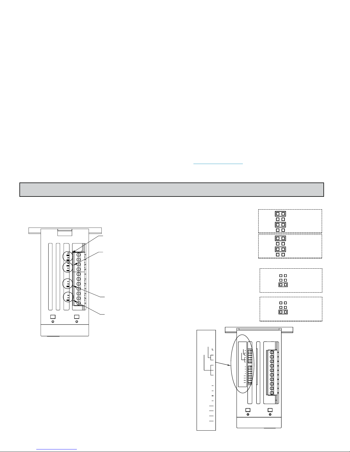
STEP 1 SETTING THE JUMPERS AND DIP SWITCHES
The jumpers are accessible from the bottom of the controller. Needle-nose
pliers are needed to remove the jumpers. They should be set prior to installation.
To insure proper operation, the jumpers must match the controller software
configuration.
Analog Output 2
Jumpers (current)
Analog Output 1
Jumpers (current)
Channel A
Input Jumpers
(RTD)
Channel B
Input Jumpers
(As set from factory)
SERIAL DIP SWITCH SETTINGS
The DLC Serial Communications Settings can be set via DIP Switches or
through the serial communications port (software selectable). The software
selectable serial settings method using the serial communications port must be
set using “RLCPRO” or another software program to write to the DLC Modbus
registers (40401-40407). When using the DIP switches to configure the serial
settings, the Modbus mode is limited to “RTU” mode only.
ANALOG DC OUTPUTS (OPTIONAL)
Analog Output 1 and Analog Output
2 can be configured for voltage (V) or
current (I), independent of each other.
Both V/I + and V/I - jumpers of the
same channel must be set for the same
type of output signal.
I2-
V2+
I2-
V2+
I1-
V1+
I1-
V1+
INPUTS
Channel A and Channel B can be
configured independent of each other.
Jumper position can be ignored for
thermocouple and millivolt inputs.
PARITY
BAUD RATE
DEFAULT
PARITY
BAUD RATE
DEFAULT
SWA
X128
SWB: ADDRESS
X64
X32
X16
X8
X4
X2
X1
M2802X
SWA
X128
SWB: ADDRESS
X64
X32
X16
X8
X4
X2
X1
M2802X
10V
20mA
RTD
10V
20mA
RTD
Analog
Output 2
Jumpers
Analog
Output 1
Jumpers
Channel A
Input
Channel B
Input
4
Page 5
SWA
SWB
DEFAULT SERIAL
SETTINGS
Use DIP Switch or
Software Serial Settings
Use Default Serial
Settings
PARITY
None DN DN
None UP
Even UP DN
Odd UP UP
SWITCH POSITION
2 3
DN
SWITCH
POSITION
1
DN
UP
BAUD RATE
300 DN DN DN
600 DN DN UP
1200 DN UP DN
2400 DN UP UP
4800 UP DN DN
9600 UP DN UP
19200 UP UP DN
38400 UP UP UP
Serial Communication Defaults:
RTUProtocol:
247Address:
9600Baud Rate:
SWITCH POSITION
4 5 6
Stop Bit:
Parity:
Start Bit
1
none
1
UNIT ADDRESS
Software Selectable
Serial Settings
1 DN DN DN DN DN DN DN UP
2 DN DN DN DN DN DN UP DN
3 DN DN DN DN DN DN UP UP
4 DN DN DN DN DN UP DN DN
5 DN DN DN DN DN UP DN UP
6 DN DN DN DN DN UP UP DN
7 DN DN DN DN DN UP UP UP
8 DN DN DN DN UP DN DN DN
…
247* UP UP UP UP DN UP UP UP
*- Unit will use address 247 for binary switch settings above 247
STEP 2 INSTALLING THE CONTROLLER
INSTALLATION
The controller is designed for attachment to standard DIN style top hat (T)
profile mounting rails according to EN50022 -35 x 7.5 and -35 x 15. The
controller should be installed in a location that does not exceed the maximum
operating temperature and provides good air circulation. Placing the controller
near devices that generate excessive heat should be avoided.
SWITCH POSITION / (BIT WEIGHT)
1
(128)2 (64)3 (32)4 (16)5 (8)6 (4)7 (2)
DN DN DN DN DN DN DN DN
8
(1)
T Rail Installation
To install the DLC on a “T” style rail, angle the controller so that the top
groove of the mounting recess is located over the lip of the top rail. Push the
controller toward the rail until it snaps into place. To remove a controller from
the rail, insert a screwdriver into the slot on the bottom of the controller, and
pry upwards until it releases from the rail.
STEP 3 IDENTIFYING THE LEDs - LED FUNCTIONALITY
On power-up, all LEDs are turned on briefly in an alternating pattern to allow visual check of LED functionality.
CONDITION CH A OP CH A ALM CH B OP CH B ALM PWR/COMMPRIORITY AUTOTUNE
Power Applied ------Communicating ------- ------- ------- -------Flashing1 ------OP1 On (Channel A) ** On ------- ------- --------------4 ------OP1 On (Channel B) ** ------- ------- On --------------4 ------AL1 On (Channel A) * ------- On ------- --------------4 ------AL1 On (Channel B) * ------- ------- ------- On-------4 ------AL2 On (Channel A) * Fast Flashing ------- --------------4 ------AL2 On (Channel B) * ------- ------- ------- Fast Flashing-------4 ------OP2 On [Cool](Channel A) Fast Flashing ------- ------- --------------5 ------OP2 On [Cool](Channel B) ------- ------- Fast Flashing --------------5 ------Auto-Tune On (Channel A) ------- ------- ------- --------------3 On
Auto-Tune On (Channel B) ------- ------- ------- --------------3 Fast Flashing
Input Error (Channel A) Slow Flashing Slow Flashing ------- --------------3 ------Input Error (Channel B)
Calibration Mode
-------3
-------2
------On
Checksum Error Slow Flashing Slow Flashing Slow Flashing Slow Flashing-------1 Slow Flashing
-------
------On
------On
------- -------On1 -------
Slow FlashingOnSlow Flashing
On
* If AL1 & AL2 outputs are on at the same time, the ALM annunciator will alternate between On and Fast Flashing every ½ second.
** If OP1 and AL2/OP2 (configured for cool) outputs are on at the same time, the annunciator will only show the OP1 state. The OP2 state is only shown when OP1 is off.
5
Page 6
STEP 4 WIRING THE CONTROLLER
WIRING CONNECTIONS
All conductors should meet voltage and current ratings for each terminal. Also, cabling should conform to appropriate standards of good installation, local codes
and regulations. When wiring the controller, use the numbers on the label to identify the position number with the proper function. Strip the wire, leaving
approximately 1/4" (6 mm) of bare wire exposed. Insert the wire into the terminal, and tighten the screw until the wire is clamped tightly. (Pull wire to verify
tightness.) Each terminal can accept up to one #14 AWG (2.55 mm), two #18 AWG (1.02 mm), or four #20 AWG (0.61 mm) wires.
24 VAC POWER
18 to 36 VDC POWER
CONTROLLER POWER CONNECTIONS
TBA
21
~
~
(AC)
(AC)
+
2
1
DC-
DC+
TBA
For best results, the power should be relatively “clean” and within the
specified limits. Drawing power from heavily loaded circuits or from circuits
that also power loads that cycle on and off should be avoided. It is recommended
that power supplied to the controller be protected by a fuse or circuit breaker.
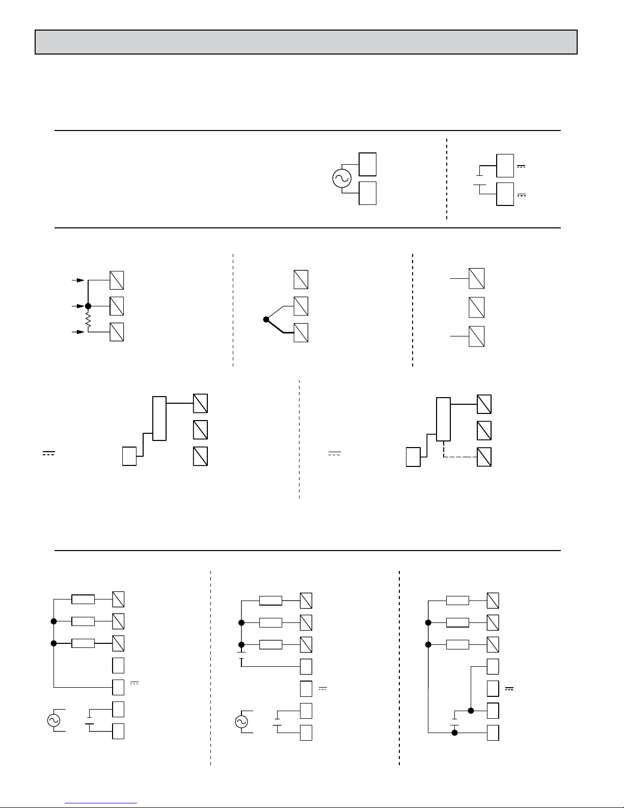
INPUT CONNECTIONS
RTD and Resistance *
0-10V, 0-20mA
Exc./
Jumper
Sense
Sense
2 Wire Current Signal Requiring DLC Excitation **
6
3
5
TC+ OR RTD
2
4
INPUT COMMON
1
CH A = Terminals 4, 5 & 6
TBB
CH B = Terminals 1, 2 & 3
RTD EXC.
-
0-10V, 0-20mA
6
3
LOAD
+
+24VDC OUT
(200 mA max)
3
TBA
CH A = Terminals 4, 5 & 6
CH B = Terminals 1, 2 & 3
* For two wire RTDs, install a copper sense lead of the same gauge and length as the RTD leads. Attach one end of the wire at the probe and the other end to input
common terminal. Complete lead wire compensation is obtained. This is the preferred method. If a sense wire is not used, then use a jumper. A temperature offset
error will exist. The error may be compensated by programming a temperature offset.
** +24 VDC OUT (Terminal 3) shares common with Ch A Inputs & All Control/Alarm Outputs.
5
TC+ OR RTD
2
4
INPUT COMMON
1
TBB
Thermocouple and Millivolt
0-10V, 0-20mA
6
3
5
TC+
TC-
RTD EXC.
TC+ OR RTD
2
4
INPUT COMMON
1
CH A = Terminals 4, 5 & 6
TBB
CH B = Terminals 1, 2 & 3
RTD EXC.
DC+
DC-
3 Wire Current or Voltage Signal Requiring DLC Excitation **
Vs
+24VDC OUT
(200 mA max)
3
TBA
CH A = Terminals 4, 5 & 6
CH B = Terminals 1, 2 & 3
Voltage or Current
6
3
2
45
1
TBB
Out
3
LOAD
Comm
2
1
TBB
0-10V, 0-20mA
RTD EXC.
TC+ OR RTD
INPUT COMMON
CH A = Terminals 4, 5 & 6
CH B = Terminals 1, 2 & 3
0-10V, 0-20mA
6
45
INPUT COMMON
RTD EXC.
TC+ OR RTD
CONTROL AND ALARM OUTPUT CONNECTIONS
Load Power from DLC
External Controller Power
+
+
+
CH A = Terminals 5, 6, & 7
CH B = Terminals 8, 9, & 10
Load
Load
Load
+
-
-
-
10
AL2/OP2
7
9
AL1
6
8
OP1
5
OUTPUT COMMON
4
3
(200 mA max)
ต
12
ต
TBA
+24VDC OUT
DC- / (AC)
DC+ / (AC)
Separate External Power
For Load and Controller
+
+
+
+
-
CH A = Terminals 5, 6, & 7
CH B = Terminals 8, 9, & 10
Load
Load
Load
+
-
-
-
TBA
10
AL2/OP2
7
9
AL1
6
8
OP1
5
OUTPUT COMMON
4
+24VDC OUT
3
DC- / (AC)
ต
DC+ / (AC)
1 2
ต
6
Combined External Power
For Load and Controller
+
+
+
CH A = Terminals 5, 6, & 7
CH B = Terminals 8, 9, & 10
Load
Load
Load
+
-
-
-
TBA
10
AL2/OP2
7
9
AL1
6
8
OP1
5
OUTPUT COMMON
4
+24VDC OUT
3
DC- / (AC)
ต
DC+ / (AC)
1 2
ต
Page 7
ANALOG DC OUTPUT CONNECTIONS
-
1110
OUT -
Controller,
Recorder
Output 1 = Terminals 8 & 9
Output 2 = Terminals 10 & 11
Note: Analog Outputs & RS485 are not internally isolated and must not
share the same common (i.e., earth ground).
+
TBB
9
8
OUT +
ANALOG OUTPUT
0-10V, 0(4)-20mA
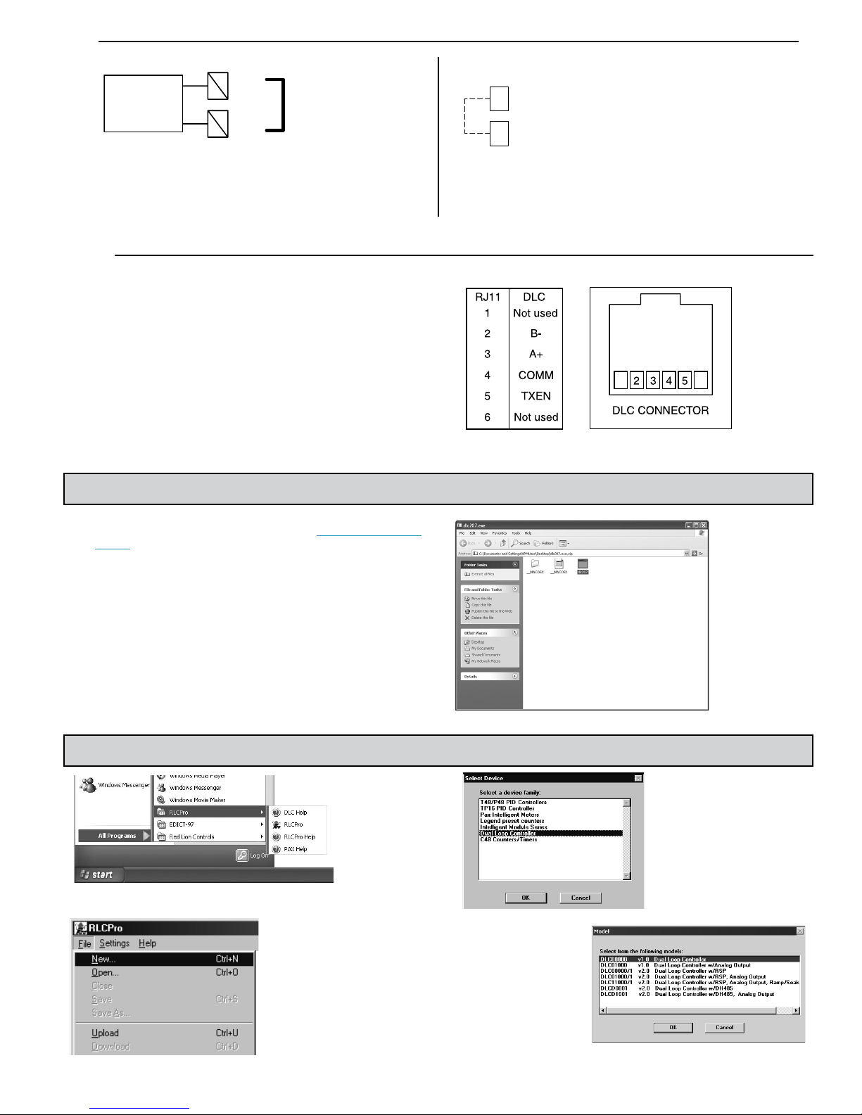
RS485 SERIAL CONNECTIONS
There are two modular connectors located on the front for paralleling
communications. The CBPRO007 programming cable converts the RS232 port
of a PC to RS485 and is terminated with an RJ11 connector. The bi-directional
capability of the CBPRO007 allows it to be used as a permanent interface cable
as well as a programming cable.
DEFAULT SERIAL SETTING CONNECTIONS
TBB
DEFAULT SERIAL
7
SETTING
OUTPUT COMMON
4
TBA
Defaults:
If using software selectable serial
settings and the serial settings are
unknown or forgotten, they can be
temporarily reset to the defaults by
connecting the “Default Serial
Setting” terminal 7 to “Output
Common” terminal 4 with a jumper.
RTUProtocol:
247Address:
9600Baud Rate:
Data Bits:
Parity:
8
none
STEP 5 INSTALLING SFDLC (Software for DLC)
After downloading RLCPro for DLC Series (http://www.redlion.net/
SFDLC) open the ZIP archive and then run dlc207.exe to install the
software.
STEP 6 PROGRAMMING - Getting Started
Run RLCPro by double-clicking the icon, or use the start menu.
You will be prompted to
select the proper device,
Use the FILE pull-down menu
to select a NEW file.
and then the model.
7
Page 8
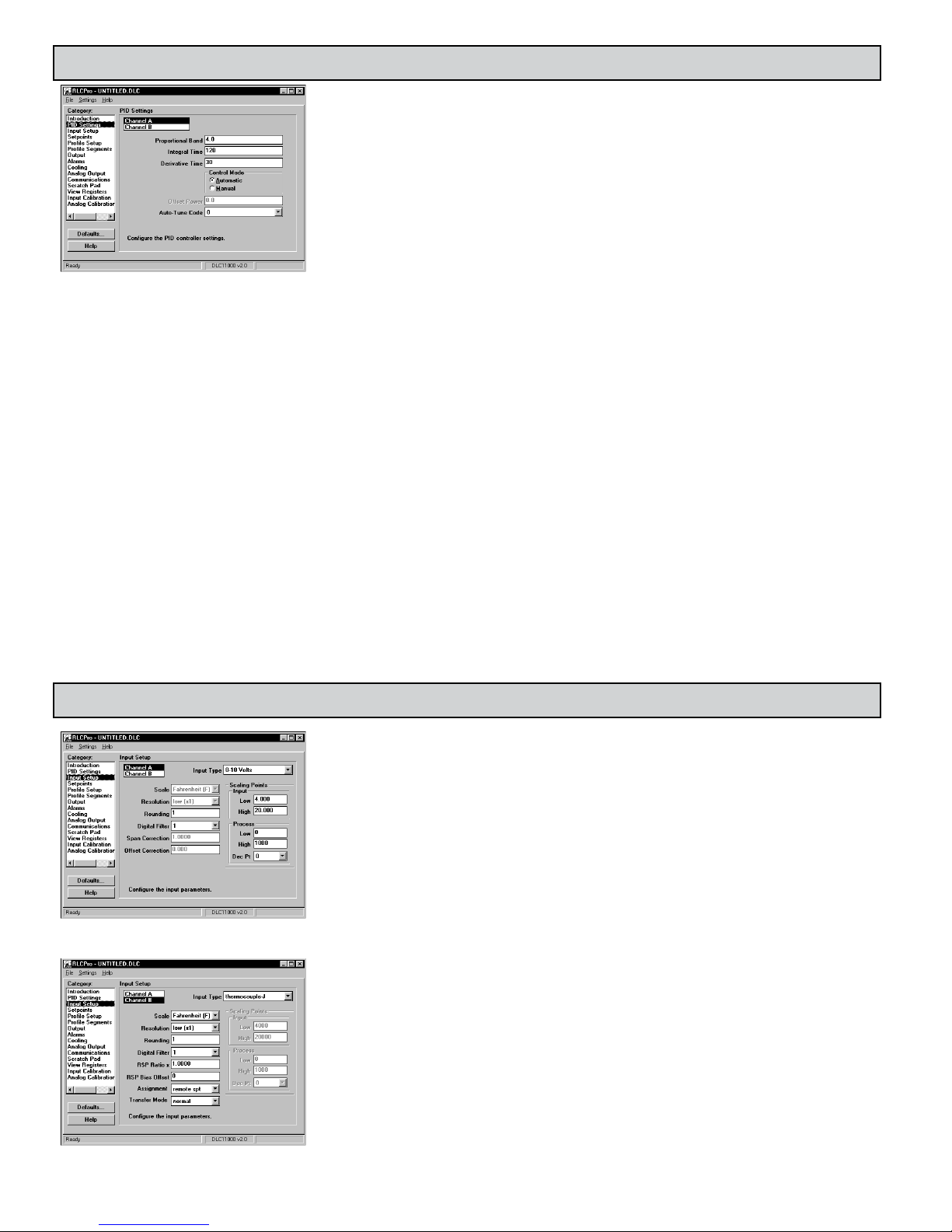
STEP 7 PROGRAMMING THE PID SETTINGS
Note: The register numbers correspond to (Channel A/Channel B).Channel B PID control is not functional
when the input is assigned as a Remote Setpoint.
The Auto-Tune procedure of the controller sets the Proportional Band, Integral Time, Derivative Time,
Digital Filter, Control Ouput Dampening Time, and Relative Gain (Heat/Cool) values appropriate to the
characteristics of the process.
Proportional Band (40007/40023): Proportional band, entered as percent of full input range, is the band from
the setpoint where the controller adjusts the percent output power based on how close the process value is
to the setpoint. For temperature inputs, the input range is fixed per the entered thermocouple or RTD type.
For process inputs, the input range is the difference between the entered Process Low Scaling Value and the
Process High Scaling Value. The proportional band should be set to obtain the best response to a process
disturbance while minimizing overshoot. A proportional band of 0.0% forces the controller into On/Off
Control with its characteristic cycling at setpoint.
Integral Time (40008/40024): Integral time is defined as the time, in seconds, it takes the output power due to integral action alone to equal
the output power due to proportional action alone during a constant process error. As long as the error exists, integral action repeats the
proportional action each integral time. Integral action shifts the center point position of the proportional band to eliminate error in the
steady state. The higher the integral time, the slower the response. The optimal integral time is best determined during PID Tuning. If time
is set to zero, the previous Integral output power value is maintained. Offset Power can be used to provide Manual Reset. Integral Action
can be disabled by writing a ‘1’ to the Disable Intergral Action register (40044/40052).
Derivative Time (40009/40025): Derivative time, entered as seconds per repeat, is the time that the controller looks ahead at the ramping
error to see what the proportional contribution will be and it matches that value every Derivative time. As long as the ramping error exists,
the Derivative action is repeated by Proportional action every derivative time. Increasing the derivative time helps to stabilize the response,
but too high of a derivative time, coupled with noisy signal processes, may cause the output to fluctuate too greatly, yielding poor control.
Setting the time to zero disables Derivative Action.
Control Mode (40041/40049): In Automatic Mode, the percentage of Output Power is automatically determined by PID or On/Off Control.
In Manual Mode, the percentage of Output Power is entered manually. For more information, see Control Mode Explanations Section.
Output Power (40005/40021): This parameter can only be changed by direct entry in Manual Mode. For more details on this parameter, see
the Control Mode Explanations Section.
Offset Power (Manual Reset) (40010/40026): If the Integral Time is set to zero (Automatic Reset is off), it may be necessary to modify the
output power to eliminate errors in the steady state. The offset power is used to shift the proportional band to compensate for errors in the
steady state. If Integral Action is later invoked, the controller will re-calculate the internal integral value to provide “bumpless” transfer.
Auto-Tune Code (40013/40029): Prior to starting Auto-Tune, this code should be set to achieve the necessary dampening level under PID
Control. When set to zero, it yields the fastest process response with possible overshoot. A setting of 2 yields the slowest response with
the least amount of overshoot. If the Auto-Tune Code is changed, Auto-Tune needs to be reinitiated for the changes to affect the PID
settings. Auto-tune is initiated by writing a ‘1’ to the Auto-Tune start register (40011/40027). The Auto-Tune phase will be shown in
register (40012/40028). For more information, see PID Tuning Explanations Section.
STEP 8 PROGRAMMING THE INPUT SETUP
Input Type (40101/40201): Select the proper input type from the pull down menu. Make sure the input
jumpers are set to match the input signal selection.
Scale (40102/40202): Select either degrees Fahrenheit or Celsius. For mV, resistance, voltage or current types,
this has no effect. If changed, check all temperature related values, as the DLC does not automatically
convert these values.
Resolution (40103/40203): For all temperature and ohms Input Types low (x1) resolution selects whole units
of measure. In these same modes, high (x10) resolution selects tenth of units of measure. For mV mode, low
selects tenths of mV and high selects hundredths of mV. If changed, be sure to check all parameters because
the controller does not automatically convert related parameter values. For voltage or current types, this has
no effect.
Rounding (40104/40204): Rounding selections other than 1 cause the process value to round to the nearest
rounding increment selected. (For example, rounding of 5 causes 122 to round to 120 and 123 to round to
125.) Rounding starts at the least significant digit of the process value. If the signal is inherently jittery, the
process value may be rounded to a value higher than 1. If the range of the signal exceeds the required
resolution (for example, 0-1000 psi, but only 10 psi resolution is required), a rounding increment of 10 will
effectively make the reading more stable.
Digital Filtering (40105/40205): The filter is an adaptive digital filter that discriminates between measurement
noise and actual process changes. If the signal is varying too greatly due to measurement noise, increase the
filter value. If the fastest controller response is needed, decrease the filter value.
Span Correction (40106/40206): This value is the correction slope. A span of 1.0000 applies no correction.
Span only applies to temperature sensor, millivolt, and ohms inputs.
Offset Correction (40107/40207): This value offsets the temperature value by the entered amount. Offset only
applies to temperature sensor, millivolt, and ohms inputs
Channel B Assignment (40198): This is used to configure Channel B to operate as a Remote Setpoint to
Channel A. Channel B PID control is not functional when the input is assigned as a Remote Setpoint.
8
Page 9
Local/Remote Setpoint Transfer Mode (40199): When cycling from/to Local or Remote Setpoint (register 40046), the response of the controller can be
programmed to act in a variety of ways. The table summarizes the responses for Setpoint transfer options.
LOCAL/REMOTE SETPOINT
TRANSFER MODE
0 - Normal Output may bump. Output may bump.
1 - Auto No output bump. Process error eliminated
at rate of integral action. Ramping disabled
during transfer.
2 - Track Output may bump. Local Setpoint (40002) assumes value
Note: In situations where an output bump may occur, the Setpoint ramp function can be used to reduce or eliminate bumping when switching Setpoint modes.
The setpoint ramp feature ramps the setpoint from the old setpoint to the new Setpoint.
Remote Setpoint Ratio Multiplier (40206): This value is used for channel B when it is assigned as a Remote Setpoint Input. The Ratio Multiplier applies to
all input types (0-15).
Remote Setpoint Bias Offset (40207): This value is used for channel B when it is assigned as a Remote Setpoint Input.
Scaling Points (40111-40114/40211-40214): Low and high scaling points are necessary to scale the controller for process voltage and current inputs. Each scaling
point has a coordinate pair of input and process value entries. The process value will be linear between and continue past the entries up to the limit of the input
range. Reverse acting measurement can be accomplished by reversing the Input or Process entries, but not both. (Do not reverse the input wires to change the
action.) To scale a 4-20 mA Input signal to provide process values of 0 to 100.00 (% in hundredths), the Input Low (40113/40213) and Input High (40114/40214)
values would be 4000 and 20000 (0.001 mA resolution), and the Process Low (40111/40211) and Process High (40112/40212) values would be 0 and 10000.
Process Decimal Point (Dec Pt) (40115/40215): The decimal point position is used to enable SFDLC display in desired engineering units for voltage and current
Process values. It is not used internally by the DLC.
LOCAL TO REMOTE REMOTE TO LOCAL
No output bump. Process error
eliminated at rate of integral action.
Ramping disabled during transfer.
of Remote Setpoint (tracks). No
output bump.
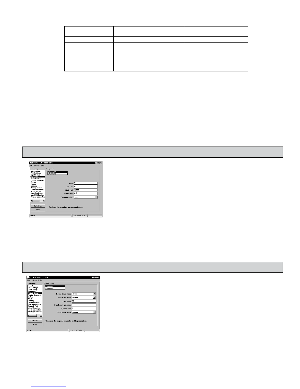
STEP 9 PROGRAMMING THE SETPOINTS
Setpoint (40002/40018): Enter the setpoint value. Deviation of Process Value (40001/40017) from
setpoint value can be viewed in the Setpoint Deviation register (40006/40022).
Low Limit (40108/40208); High Limit (40109/40209): The controller has programmable high and low
setpoint limit values to restrict the setting range of the setpoint. Set the limits so that the setpoint value
cannot be set outside the safe operating area of the process.
Ramp Rate (40110/40210): The setpoint ramp rate can reduce sudden shock to the process and reduce
overshoot on startup or after setpoint changes, by ramping the setpoint at a controlled rate. The ramp
rate is 0.1° for input types 0-11, 0.1 Ω for input type 12, 0.01 for input type 13, and 0.1 unit for input
types 14-15 per minute. Writing a ‘0’ disables setpoint ramping. The Disable Setpoint Ramping register
(40042/40050) can also be used to disable ramping. The Setpoint Ramping In-Process register
(40043/40051) will be a ‘1’ during setpoint ramping. While ramping is enabled, the Ramping Setpoint
can be viewed in register (40045/40053). The Ramp Rate for CHB is not functional when it is assigned
as a Remote Setpoint Input.
Once the ramping setpoint reaches the target setpoint, the setpoint ramp rate disengages until the setpoint is changed again. If the ramp value is changed
during ramping, the new ramp rate takes effect. If the setpoint is ramping prior to starting Auto-Tune, the ramping is suspended during Auto-Tune and then
resumed afterward using the present Process value as a starting value. Deviation and band alarms are relative to the target setpoint, not the ramping setpoint. A
slow process may not track the programmed setpoint rate. At power-up, the ramping setpoint is initialized to the starting process value.
Remote/Local Setpoint Select (40046): Channel A setpoint mode can be switched between Local Setpoint operation and Remote Setpoint operation. The
Channel B input must be assigned as a remote setpoint (register 40198).
STEP 10 PROGRAMMING PROFILE SETUP (Optional)
Profile Power Cycle Mode (40321/40421): Upon controller power-on several profile operating modes
exist.
Stop: If the Profile was running when powered down, upon power-up, "Stop" places the profile into the
stop or off mode, regardless of the mode prior to the power-down. The active Setpoint is the setpoint
of the last segment that ran before power-down.
Abort: If the Profile status was running, paused, or in Error Delay when powered down, upon power-up,
"Abort" will place the controller in manual mode at 0% Output Power. The Setpoint and Ramp Rate
are the values they were prior to running the profile. If the Setpoint Controller was 'paused,' they will
be set to the values that they were at power-down.
Start: The Start power cycle mode causes the controller to automatically start the profile at Power-up.
This will occur if the unit was in manual or automatic control mode. During maintenance or at other
times when this action is not desired, the Profile Power Cycle mode should be changed appropriately.
Resume: At Power-up, Resume causes the profile to continue from the point and phase when power was
removed. If the unit was in ramp phase, the ramping setpoint will start ramping from the initial
process value at power-up.
Pause: Upon Power-up, the controller pauses and maintains control at the initial process value (on
power-up), at the phase where the controller was powered down. The user can then determine how to
proceed based on the process that is being controlled.
9
Page 10

Profile Error Band Mode (Guaranteed Soak) (40322/40422): Profile conformity can be assured by using the profile Error Band Mode and Error Band
parameter. If the process value deviates outside the error band value while a profile is running, the controller enters the delay mode. In the delay mode,
the profile phase timer is held (delayed) until the process value is within the deviation error band value - the Error band hysteresis value. At this time, the
profile continues running unless the process value again deviates. These actions assure that the actual process value conforms to the profile.
Disable Error Band: Error band operation is disabled.
Ramp Phase Only Error Band: The Profile Error Band only applies to the ramp phases of the running profile.
Hold Phase Only Error Band: The Profile Error Band only applies to hold phases of the running profile.
Ramp & Hold Phase Error Band: The Profile Error Band applies to both ramp and hold phases of the running profile.
Profile Error Band (40323/40423): During a hold phase, the profile is paused when the process error is >= the Profile Error Band. The profile will remain
paused until the process error (deviation) is within the Profile Error Band (Error Band-Error Band Hysteresis).
Profile Error Band Hysteresis (40324/40424): Controls the process value at which the profile will come out of an error band delay. If in error band delay,
the profile phase timer is held (delayed) until the process value is within the deviation error band value - the Error band hysteresis value.
Profile End Segment (40325/40425): The Profile End Segment indicates the last segment (i.e., the number of segments to be used in a profile) that is to be
ran in the profile before it stops or re-starts (dependent on Profile Cycle Count/Profile Cycle Count remaining).
Profile Cycle Count (40326/40426): Once a profile is started, it runs the number of cycles programmed in this register and then automatically defaults to
the Profile End Control Mode. If this parameter is changed while the profile is active, the new value (if less than 250) will not take effect until the profile
is stopped and re-started. If the Profile Cycle Count is set to 250 (continuous profile cycling), the change will take affect immediately.
Profile End Control Mode (40327/40427): This parameter sets the type of control action that will be used when the number of profile cycles as programmed
in the Profile Cycle Count parameter has run to completion.
Control Outputs Off : Control is turned off by putting the controller in manual mode at 0% Power. Control can be resumed by changing the Control
Mode (40041/40049) to Automatic.
Automatic: When configured for Automatic the controller will continue controlling at the last setpoint value.
Setpoint Controller Setpoint Segment Registers 1-20 (40601-40620[ChA]/40701-
40720[ChB]): The setpoints for the profile are written in these registers. The values are limited
by the Setpoint Lo and Setpoint Hi limits registers. Register (40601/40701) is the Setpoint for
the 1st segment of the profile.
Setpoint Controller Ramp Rate Segment Registers 1-20 (40621-40640[ChA]/40721-
40740[ChB]): The Ramp Rates for the profile are written in these registers. Register
(40621/40721) is the Ramp Rate for the 1st segment of the profile. A ramp rate of 0 disables
setpoint ramping.
Setpoint Controller Hold Time Segment Registers 1-20 (40641-40660[ChA]/40741-
40760[ChB]): The Hold Times for the profile are written in these registers. Register
(40641/40741) is the Hold Time for the 1st segment of the profile. Segment Hold times of 0
can be used to achieve a ramp with multiple slopes.
STEP 11 MONITORING PROFILE OPERATION (Optional)
Profile Operating Status/Mode (40065/40073)
Stop/Off: The Stop/Off status indicates the profile is dormant or off. A profile can be stopped by setting this register to 0, by allowing a profile to run to
completion, or by removing and re-applying power when the Power Cycle Mode is configured for stop. If the profile was terminated during a ramp
phase, the unit will continue to ramp to the active setpoint.
Abort: Abort is a command action that can be used quickly to stop the profile and turn off the control outputs. The controller is placed into manual mode
at 0% output power. Following the abort command the Profile Operating Status will go to 0 (Stop/Off).
Run/Start: The profile is in the run mode when it is executing. While running, the profile can be stopped (0), paused (3), or advanced to the next phase.
A profile can be started and placed into the Run mode automatically when the controller is powered-up (see Profile Power Cycle Mode). If the profile
was previously stopped, when it is placed in to the Run/Start mode (2), the controller will be put into automatic control (if it was in manual) and start
the profile at the first segment. If the controller was in manual mode prior to starting the profile, the controller will start ramping from the current
process value. If the profile was "paused," it will resume operation. The advancement of the profile can be viewed in the Profile Phase (40066/40074)
and Profile Segment register (40067/40075).
10
Page 11

Pause: Pause signifies that a profile is active but the time base (Profile Phase Timer) is paused. The pause mode can only be invoked by writing a
3 in the Profile Operating Status register. Pausing a profile during a ramp phase pauses the ramp and the controller maintains control at the
ramping setpoint value (40045/40053) at the instant of the pause action. The use of pause, effectively lengthens the total run time of a profile.
The unit will remain in pause mode until it is placed back in the run mode by writing a 2 (Run/Start) into the Profile Operating Status Register.
Error Delay (Guaranteed Soak): The Error Delay Setting is used only as a status indication. It indicates that a profile is active but the phase timer
or profile advancement has stopped. This is caused by automatic action of the controller when the process deviates more than a specified amount
from the active profile segment. The Error Delay is similar to pause, except the error delay status can only be invoked automatically. See "Profile
Error Band Mode (40322/40422)." Do not write a "4 - Error Delay," to the Profile Operating Status Register. Doing so will instead put the
controller in pause mode (3).
Profile Phase (40066/40074): When the profile is active, this register indicates whether the controller is in a ramp (0) or hold (1) phase.
Profile Segment (40067/40075): Indicates the current active segment while the profile is running. A zero indicates that the profile is stopped or off.
Profile Phase Timer (40068/40076): This register shows the remaining segment phase time in 10ths of minutes. The remaining phase time can be
changed "on the fly" to accelerate or decelerate the phase time. The change in phase time will only affect the running profile and not the stored
parameters. If the phase time is changed during the ramp phase, a new ramp rate will be calculated which will achieve the desired phase time. The
Profile Phase Timer will stop while the unit is paused or during an error delay caused by Profile Error Band operation (guaranteed soak).
Profile Cycle Count Remaining (40069/40077): Indicates the number of profile cycles that are yet to be run. If the Profile Cycle Count register
(40326/40426) is set to 250, the Profile Cycle Count Remaining Register will run continuously, resetting to "250" when reaching "0". This register
value can be changed, however, it will only affect the current run cycle. When the profile is stopped and re-started, the Profile Cycle Count
Remaining Register will be reloaded based on the "Profile Cycle Count (40326/40426)" value.
Advance Profile Phase (40070/40078): Writing a "1" to this register while the profile is running will cause the controller to advance immediately to
the beginning of the next ramp or hold phase. Using the advance operation shortens the total run time of the profile. If the profile is "paused," the
profile will advance but the profile will remain paused. The Profile can also be advanced while in the error delay mode.
STEP 12 PROGRAMMING THE OUTPUTS
Cycle Time (40116/40216): The cycle time, entered in seconds, is the combined time of an on and off
cycle of a time proportioning control output OP1/OP2. With time proportional output, the percentage
of control power is converted into output on time of the cycle time value. (If the controller calculates
that 65% power is required and has a cycle time of 10 seconds, the output will be on for 6.5 seconds
and off for 3.5 seconds.) For best control, a cycle time equal to one-tenth of the process time constant,
or less, is recommended. When using the DC Analog output signal for control, a setting of zero will
keep output OP1 off. The status of OP1 can be read through registers 40014/40030.
Control Action (40117/40217): This determines the control action for the PID loop. Programmed for
direct action (cooling), the DLC output power will increase if the Process value is above the Setpoint
value. Programmed for reverse action (heating), the output power decreases when the Process Value is
above the Setpoint Value. For heat and cool applications, this is typically set to reverse. This allows
OP1 to be used for heating, and AL2/OP2 to be used for cooling.
Power Low Limit (40118/40218); High Limit (40119/40219): These parameters may be used to limit controller power due to process disturbances
or setpoint changes. Enter the safe output power limits for the process. If Alarm 2 is selected for cooling, the range is from -100 to +100%. At 0%,
both OP1 and OP2 are off; at 100%, OP1 is on; and at -100%, OP2 is on. When the controller is in Manual Control Mode, these limits do not apply.
Sensor Fail Power Preset (40120/40220): This parameter sets the power level for the control outputs in the event of a sensor failure or extreme
overdriven/underdriven input. If Alarm 2 is not selected for cooling, the range is from 0% (OP1 output full off) to 100% (OP1 output full on). If
AL2 is selected for cooling, the range is from -100 to +100%. At 0%, both OP1 and OP2 are off; at 100%, OP1 is on; and at -100%, OP2 is on. The
alarm outputs are upscale drive with an open sensor, and downscale drive with a shorted sensor (RTD only), independent of this setting. Manual
Control overrides the sensor fail preset.
Dampening Time (40121/40221): The dampening time, entered as a time constant in seconds, dampens (filters) the calculated output power.
Increasing the value increases the dampening effect. Generally, dampening times in the range of one-twentieth to one-fiftieth of the controller’s
integral time (or process time constant) is effective. Dampening times longer than these may cause controller instability due to the added lag effect.
On/Off Control Hysteresis (40122/40222): The controller can be placed in the On/Off Control Mode by setting the Proportional Band to 0.0%. The
On/Off Control Hysteresis (balanced around the setpoint) eliminates output chatter. In heat/cool applications, the control hysteresis value affects
both Output OP1 and Output OP2 control. It is suggested to set the hysteresis band to 2 (Factory Setting) prior to starting Auto-Tune. After AutoTune, the hysteresis band has no effect on PID Control. On/Off Control Hysteresis is illustrated in the the On/Off Control Mode section.
11
Page 12

STEP 13 PROGRAMMING THE ALARMS
Deviation Low Acting (AL > 0)
Alarm 1 and 2: The controller is equipped with two alarms for each channel. The status of these alarms
can be read through AL1 registers 40015/40031 and AL2 registers 40016/40032.
Action (40131/40231), (40136/40236): Select the action for the alarms. See Alarm Action Figures for a
visual explanation.
Manual: In Manual mode, the alarms are forced on and off by writing ‘0’ or ‘1’ to the appropriate
alarm output register. In this mode, the alarms will not respond to Alarm and Hysteresis Values.
Absolute HI (balanced or unbalanced hysteresis): The alarm energizes when the Process Value exceeds
the alarm.
Absolute LO (balanced or unbalanced hysteresis): The alarm energizes when the Process Value falls
below the alarm.
Deviation HI, Deviation LO, Band Acting: In these actions, Alarm 1 and 2 value tracks the Setpoint
value.
Cooling (OP2): For heat/cool applications, select Cool for Alarm 2. The controller then utilizes the
Alarm 2 output as the Cooling Output (OP2). If cooling is selected, the remaining Alarm 2
parameters are not available.
ALARM ACTION FIGURES
AL + ½Hys
AL - ½Hys
AL + ½Hys
AL - ½Hys
ALARM
STATE
AL - Hys
ALARM
STATE
AL
ALARM
STATE
OFF
TRIGGER POINTS
Absolute High Acting (Balanced Hys)
AL
OFF ON
TRIGGER POINTS
Absolute Low Acting (Balanced Hys)
AL
OFF ON
TRIGGER POINTS
Absolute High Acting (Unbalanced Hys)
SP + (-AL)
SP + AL
SP - AL
ALARM
STATE
SP + AL
SP - AL
ALARM
STATE
SP
ALARM
ON OFF
STATE
TRIGGER POINTS
Deviation High Acting (AL< 0)
SP
ON
OFF OFF
SP
ON OFF OFFON ON
OFF
TRIGGER POINTS
Band Outside Acting
TRIGGER POINTS
Band Inside Acting
Hys
ON
Hys
Hys
ON
Hys
Hys
AL + Hys
Hys
AL
ON
OFF
OFF
OFF
Hys
Hys
SP + AL
SP - AL
ALARM
STATE
ALARM
STATE
ALARM
STATE
SP
OFF ON
SP
OFF ON
Deviation High Acting (AL > 0)
OFFON
TRIGGER POINTS
OFF
TRIGGER POINTS
OFF
TRIGGER POINTS
Hys
OFF
Hys
Hys
Note: Hys in the above figures refers to the Alarm Hysteresis.
Value (40003/40019), (40004/40020): The alarm values are entered as process units or degrees.
Hysteresis (40134/40234), (40139/40239): The Hysteresis Value is either added to or subtracted from the alarm value, depending on the alarm action selected.
See the Alarm Action Figures for a visual explanation of how alarm actions are affected by the hysteresis.
Trigger Points: Trigger points are the Process Values where the alarm state changes. Their values cannot be entered directly, but are shown as a reference in the
SFDLC software. The alarm value, hysteresis value, and setpoint alarm type determine the trigger points. With Deviation or Band actions, the alarm value and
setpoint value are combined to determine the trigger points. Trigger points must not be greater than +32000 or less than -32000. If these limits are exceeded,
the alarm may not function properly.
Reset (40132/40232), (40137/40237): The alarms can be programmed for Automatic or Latched. In Automatic mode, an energized alarm turns off automatically
once the Process Value leaves the alarm region. In Latched mode, an energized alarm requires a manual reset. This is done by writing ‘0’ to the appropriate
output status register. After writing ‘0’, the Automatic or Latched alarm will not turn on again until after the Process Value first returns to the alarm off region.
Only alarms configured for Manual action can be energized by writing a ‘1’ to its’ alarm output status register.
On Delay (40135/40235), (40140/40240): The time, in seconds, required for the Process Value to be in the alarm region before the alarm will activate. It is used
to allow temporary or short excursions into the alarm region without tripping the alarm.
Enable Standby Delay (40133/40233), (40138/40238): Standby prevents nuisance (typically low level) alarms after a power up or setpoint change. After
powering up the controller or changing the setpoint, the process must leave the alarm region. Once this has occurred, the standby is disabled and the alarm
responds normally until the next controller power up or setpoint change.
12
Page 13

STEP 14 PROGRAMMING THE COOLING
To enable Cooling in Heat/Cool applications, the Alarm 2 Action must first be set for Cooling. When
set to cooling, the output no longer operates as an alarm but operates as an independent cooling output.
The OP2 terminals are the same as AL2. Cooling output power ranges from -100% (full cooling) to 0%
(no cooling, unless a heat/cool deadband overlap is used). The Power Limits in the Output category also
limits the cooling power.
Cycle Time (40141/40241): This cycle time functions like the OP1 Output Cycle Time but allows
independent cycle time for cooling. A setting of zero will keep output OP2 off. The status of OP2 can
be read through registers (40016/40032).
Relative Gain (40142/40242): This defines the gain of the cooling relative to the heating. It is generally
set to balance the effects of cooling to that of heating. This is illustrated in the Heat/Cool Relative Gain
Figures. A value of 0.0 places the cooling output into On/Off Control. This may be done independent
of the OP1 Output PID or On/Off Control Modes.
Deadband (40143/40243): This defines the area in which both heating and cooling are active (negative
value) or the deadband area between the bands (positive value). If a heat/cool overlap is specified, the
percent output power is the sum of the heat power (OP1) and the cool power (OP2). If Relative Gain
is zero, the cooling output operates in the On/Off Control Mode, with the Deadband value becoming
the cooling output hysteresis (positive value only). This is illustrated in the On/Off Control Mode
section. For most applications, set this parameter to 0.0 prior to starting Auto-Tune. After the
completion of Auto-Tune, this parameter may be changed.
HEAT/COOL RELATIVE GAIN FIGURES
%
OUTPUT
POWER
2X PROPORTIONAL
O1
+100%
Heat/Cool Deadband = 0
BAND
SETPOINT
DEADBAND
O2
-100%
%
OUTPUT
POWER
COOLHEAT
TEMPERATURE
O1
+100%
POSITIVE VALUE
HEAT
SETPOINT
RELATIVE GAIN
21 .5
RELATIVE GAIN = .5
COOL
O2
-100%
TEMPERATURE
Heat/Cool Deadband > 0
DEADBAND
NEGATIVE VALUE
RELATIVE GAIN
RELATIVE GAIN = .5
COOL
.512
O2
-100%
TEMPERATURE
%
OUTPUT
POWER
O1
+100%
HEAT
SETPOINT
Heat/Cool Deadband < 0
13
Page 14

STEP 15 PROGRAMMING THE ANALOG OUTPUT (Optional)
Note: The register numbers correspond to (Analog Output 1/Output 2).
Assignment (40301/40309): This setting selects the value that the Analog Output will retransmit, or track.
The Analog output can be assigned for the following:
SELECTION DESCRIPTION
Output Power A
Process Value A
Setpoint A Retransmits Setpoint Value Channel A
Ramping Setpoint A Retransmits Ramping Setpoint Channel A
Deviation A Retransmits Deviation (difference of Setpoint Value - Process Value) Channel A
Direct Entry Value 1 Retransmits Direct Entry Value 1 (Manual Analog Control)
Output Power B Transmits the Output Power demand of Channel B. Used if linear control is desired.
Process Value B Retransmits Process Value Channel B
Setpoint B Retransmits Setpoint Value Channel B
Ramping Setpoint B Retransmits Ramping Setpoint Channel B
Deviation B Retransmits Deviation (difference of Setpoint Value - Process Value) Channel B
Direct Entry Value 2 Retransmits Direct Entry Value 2 (Manual Analog Control)
Mode (40302/40310): Select the type of output and range. The Analog output jumpers must be set to match the
output type and range selected. The Analog output can be calibrated to provide up to 5% of over range operation.
Output Scaling Values: The Scaling Low value (40303/40311) corresponds to 0 V, 0 mA or 4 mA, depending on
the range selected. The Scaling High value (40304/40312) corresponds to 10 V or 20 mA depending on the range
selected. An inverse acting output can be achieved by reversing the Scaling Low and Scaling High points.
Deadband (40305/40313): The output power change must be greater than the deadband value in order for the
Analog output to update. This only applies when the Analog Output is assigned to Output Power. This setting
can be used to reduce actuator activity.
Update Time (40306/40314): To reduce excess valve actuator or pen recorder activity, the update time of the
analog output can be set in seconds. A value of zero seconds results in an update time of 0.1 second.
Direct Entry Value (40307/40315): If the analog output is programmed for Direct Entry, it retransmits this value.
This value may be controlled by the host.
Filter (40308-40316): Entering a 1 will apply averaging when the Update Time >=1.
Transmits the Output Power demand of Channel A. Used if linear control is desired.
Retransmits Process Value Channel A
STEP 16 PROGRAMMING THE DLC COMMS PORT
Note: If the software selectable communication settings are changed and then a download is performed, the
controller will immediately respond to the new settings. Any further attempts to communicate to the controller
must target the new address, with the new settings.
SERIAL SETTINGS
MODBUS Protocol (40405): RTU or ASCII
Unit Address (40401): 1-247
Baud Rate (40402): 300 to 38400
Data Bits (40404): 7 or 8
Parity (40403): odd, even, or none
Transmit Delay (40406): Programmable from 2-250 milliseconds.
The Transmit Delay is the time the DLC waits to respond to a serial
command, UNLESS the values in the table are larger.
Note: Changing the above parameters by writing to their registers
directly will not update the DLC until Load Serial Settings register
40407 is a ‘1’. After a write, this register will return to ‘0’.
DIP Switch Serial Settings: The DIP switches can be used to select the
baud rate, parity, and unit address. When using the DIP switches to
configure the serial settings, the Modbus communications mode will be RTU only. There is also a "Default Serial
Settings" switch to quickly configure the DLC for use with the "RLCPRO" Programming Software.
Software Selectable Serial Settings: Setting all of the DIP switches to the "off" position and having the "Default
Serial Setting" terminal un-connected, enables Software Selectable Serial settings. When leaving the factory the
Software Selectable serial settings are set to the Serial Communication Defaults. Software Selectable Serial
Settings allows set-up of all serial settings including the choice of RTU or ACSII communications modes and the
number of data bits. If the Software Selectable Serial Settings are changed, the load serial register must be used
or power to the DLC must be removed and re-applied in order for the settings to take effect. The use of RLCPRO
Programming software or another software program supporting Modbus protocol is required to write to the DLC
serial settings registers (40401-40407).
MINIMUM TRANSMIT DELAY
BAUD RTU ASCII
38400 2 msec 2 msec
19200 3 msec 2 msec
9600 5 msec 2.3 msec
4800 9 msec 4.6 msec
2400 17 msec 9.2 msec
1200 33 msec 18.4 msec
600 65 msec 36.7 msec
300 129 msec 73.4 msec
14
Page 15

Default Serial Settings: The DLC serial port can be temporarily set to the factory defaults by setting the Default serial communications DIP switch to
the “up” position OR by placing a jumper from the “Default Serial Setting” terminal 7 (TBB) to Output common terminal 4 (TBA). Both of these
have precedence over the DIP switch serial settings and the software selectable serial settings. Once the serial default DIP switch is set to the “off”
position or the jumper is removed, the DLC serial settings will immediately change as programmed by the DIP switches or the software selectable
serial settings if all of the DIP switches are in the “off” position. The Default Serial Settings are NOT loaded into the software selectable serial
registers when the serial default setting switch/terminal is active, they must be explicitly changed.
Serial Communication Defaults: 9600 baud, 1 start bit, no Parity, 1 stop bit, address 247, and RTU mode.
Communications Diagnostics: The Communications Diagnostics function (MODBUS Function Code 08) can be used to troubleshoot systems that are
experiencing communication errors. Press the Read button to retrieve the diagnostics information. The Commands Received and the Commands
Processed values are automatically reset when the values are read, at each controller power-up, and when the Commands Received reaches 65536.
Commands Received: The total number of messages received that started with the controller’s own address since the last reset or power up.
Commands Processed: The number of “good” messages received. A “good” message is considered one that contained the correct unit address,
parity, and checksum (CRC or LRC).
STEP 17 PC PORT CONFIGURATION
Go to the SETTINGS pull-down menu, and select PC PORT SETTINGS.
The Communications Settings window allows you to set up the software properly to perform a download.
Connection: Select the computer port (COMM 1-4) that the DLC is connected to.
Note: The following settings must match the DLC. If you do not know or cannot recall the DLC settings, they can
be temporarily set to factory defaults. Simply jumper the Default Serial Setting terminal 7 to Input Common
terminal 4 or put the Default Serial Settings DIP switch in the “UP” position. The serial settings will default
to RTU mode, 9600 baud, 8 data bits, no parity, with an address of 247.
Protocol: RTU or ASCII
Unit Address: 1-247
Baud Rate: 300, 600, 1200, 2400, 4800, 9600, 19200, 38400
Data Bits: 7 or 8
Parity: odd, even, or none
Connect the DLC to the computer with the CBPRO007 interface cable (or any suitable RS232/RS485 converter).
Apply power to the supply terminals of the DLC.
Note: The CBPRO007 download cable DOES NOT
typically require power. In most cases it will derive
its power from the PC. If communications can not be
established, follow the troubleshooting guide. If it is
determined that the converter requires power, attach
a 12 VDC power supply to the VDC and common
terminals of the cable.
STEP 18 DOWNLOADING
Go to the FILE pull-down menu, and select DOWNLOAD.
The following screen prompts you to
ensure that the proper file is downloaded
to the correct controller. Click “OK” to
continue.
CBPRO
DLC
RED LION CONTROLS
MODEL DLC
PWR/COMM.
CH A OP
BOTH FLASHING
=
INPUT ERROR
CH A ALM
AUTOTUNE
CH B OP
BOTH FLASHING
=
INPUT ERROR
CH B ALM
ALL FLASHING = CHECKSUM ERROR
RS485
MODBUS
PROTOCOL
15
Page 16

STEP 19 SCRATCH PAD MEMORY
The Scratch Pad category can be used to read or write to the Scratch Pad memory locations (41101-
41116). The Scratch Pad locations can be used to store user information.
Data Format: Allows registers to be viewed in decimal or hexadecimal format.
Upload: The Upload button causes SFDLC software to read the Scratch Pad registers from the controller.
Download: The Download button causes SFDLC software to write to the Scratch Pad registers in the
controller.
Note: Downloading new values to the controller Scratch Pad locations overwrites the information that is
currently stored in those registers.
Defaults: For this category, there are no controller factory defaults. The defaults for this category are only
SFDLC software basic default values.
STEP 20 VIEW REGISTERS
The View Registers category can be used as a method of diagnostics. Use the DLC Register Table as a
reference of register assignments and data.
First Register: This specifies the first register to be read in a block.
# of Registers: This is the length of the block to be read. The controller supports block read and write
commands up to 32 registers in length. The SFDLC software only allows 16 to be read in a block.
Data Format: Allows registers to be viewed in decimal or hexadecimal format.
Read: Clicking the Read button causes SFDLC software to read the selected registers from the controller.
Write: Clicking the Write button causes SFDLC software to write the selected registers to the controller.
Note: The Write button overwrites the existing register values, and may change the module setup and
operation.
Defaults: For this category, there are no controller factory defaults. By clicking Defaults, the present
entries from the other SFDLC software category screens will be displayed.
STEP 21 CALIBRATION
The DLC is fully calibrated from the factory. Recalibration is recommended every two years. Each channel is calibrated separately. All calibration settings
are stored in the non-volatile memory. Calibration may be performed by using SFDLC software or MODBUS commands. When using SFDLC for calibration,
connect the signal or measuring source to the proper DLC terminals, verify the input or output jumper positions, select the type of calibration to be performed,
and click the Calibrate button. Follow the calibration procedures in the software.
Note: Allow the DLC to warm up for 30 minutes minimum and follow the manufacturer’s warm-up recommendations for the calibration source.
INPUT CALIBRATION
When calibrating the input, the millivolt calibration must be performed first. All other input types use the
millivolt points. Each input range (non-thermocouple) also has its own internal references that are recalled
when the range is selected. Non-used types need not be calibrated.
Calibration Type: This specifies the type of calibration to be performed.
Millivolt: Millivolt calibration requires a precision voltage source with an accuracy of 0.03% or better.
It is used for thermocouple inputs and as a basis for all other input calibration types.
RTD: RTD calibration requires a 0.1% (or better) precision 277.0 ohm resistor.
Process Voltage: Process calibration requires a precision signal source with an accuracy of 0.03% (or
better) that is capable of generating 10.00 V.
Process Current: Process current calibration requires a precision signal source with an accuracy of
0.03% (or better) that is capable of generating 20.00 mA.
Cold Junction: Cold Junction calibration requires a thermocouple of known accuracy of types T, E, J, K, C or N only and a calibrated external reference
thermocouple probe.
TC Type: This selects the type of TC that is being used to calibrate the cold junction.
Scale: This selects the scale in which the Thermometer temperature is entered and the controller temperature is displayed.
Thermometer: Enter the reference thermometer temperature here.
DLC: This displays the DLC process temperature value after a cold junction calibration is completed to verify the accuracy.
Calibrate: The Calibrate button initiates the calibration process after the appropriate settings are selected.
16
Page 17

ANALOG OUTPUT CALIBRATION
PROTOCOL
MODBUS
RS485
RS485
PROTOCOL
MODBUS
RS485
MODBUS
PROTOCOL
ZONE 4ZONE 3
FOUR-ZONE EXTRUDER
POWER
18-36VDC/
24VAC
0-10V SIG.
4-20mA SIG.
(FROM PRESSURE
(FROM MOTOR DRIVE)
+
SENSOR)
HMI UNIT
++
ZONE 2
+
ZONE 1
MODEL DLC
RED LION CONTROLS
MODEL DLC
RED LION CONTROLS
MODEL DLC
RED LION CONTROLS
Calibration Type: This specifies the Analog Output point to be calibrated.
Volts: Analog Output Voltage calibration requires a precision meter with an accuracy of 0.05% (or better)
that is capable of measuring 10.00 V.
mA: Analog Output Current calibration requires a precision meter with an accuracy of 0.05% (or better)
that is capable of measuring 20.00 mA.
Meter Value: After pressing the Calibrate button, this shows the value the DLC is outputting. Measure the
actual output with an external meter and enter that value here. Press the Calibrate button again and follow
the prompts.
Calibrate: The Calibrate button initiates the calibration process after the appropriate settings are selected.
APPLICATION
A plastic extrusion company was building a four-zone extruder, and wanted a centrally located,
multi-zone interface. The interface needed to display the temperature and setpoint values, as well as
the screw RPM and barrel pressure. The customer provided a speed proportional 0-10 Volt signal
from a motor drive, and installed a 4-20 mA output pressure sensor in the extruder barrel. Each of
the four heat/cool zones were equipped with a thermocouple.
Three DLC-Dual Loop Controllers, with a G3 HMI, allowed the customer to build his own control
system. Only three DLCs were required; two were needed to control the four temperature zones, and
one was needed to monitor the two process signals.
CONTROL MODE EXPLANATIONS
All three units were
connected to the RS485
port of the G3 display. The
customer created his own
displays on the HMI,
which allowed him to
monitor and control the
setpoints and alarms
within the DLCs. The G3’s
multi-protocol capability
allowed it to tie the DLCs
to his PLC, creating a true
centralized interface.
MANUAL CONTROL MODE
In Manual Control Mode, the controller operates as an open loop system
(does not use the setpoint and process feedback). The user enters a percentage
of power through the Output Power register (40005/40021) to control the heat
(reverse) or cool (direct) for Output OP1. When Alarm 2 is configured for
Cooling (OP2), Manual operation provides 0 to 100% power to OP1 (heating)
and -100 to 0% power to OP2 (Cooling). The Low and High Power limits are
ignored when the controller is in Manual.
For time proportional outputs, the output power is converted into output On
time using the Cycle Time. For example, with a four second cycle time and 75%
power, the output will be on (4 × 0.75) for three seconds and off for one second.
For Analog Outputs (0-10 VDC or 0/4-20 mA), the percent output power is
converted into a linear value according to the Percent Low and High scaling set
for the analog output. For example, with 0 VDC (scaled 0.0%) to 10 VDC
(scaled 100%) and 75% power, the analog output will be 7.5 VDC.
MODE TRANSFER
When transferring the controller mode from or to Automatic, the controlling
outputs remain constant, exercising true bumpless transfer. When transferring
from Manual to Automatic, the power initially remains steady, but Integral
Action corrects (if necessary) the closed loop power demand at a rate
proportional to the Integral Time. The Control Mode can be changed through
the Control Mode register (40041/40049).
AUTOMATIC CONTROL MODE
In Automatic Control Mode, the percentage of output power is automatically
determined by PID or On/Off calculations based on the setpoint and process
feedback. For this reason, PID Control and On/Off Control always imply
Automatic Control Mode.
17
Page 18

ON/OFF CONTROL
Output 2 (OP2) :
INPUT
P & I
The controller operates in On/Off Control when the Proportional Band is set
to 0.0%. In this control, the process will constantly oscillate around the setpoint
value. The On/Off Control Hysteresis (balanced around the setpoint) can be
used to eliminate output chatter. Output OP1 Control Action can be set to
reverse for heating (output on when below the setpoint) or direct for cooling
(output on when above the setpoint) applications.
ON/OFF CONTROL - REVERSE OR DIRECT ACTING FIGURES
INPUT
SP+1/2 HYS
SP
SP-1/2 HYS
Output 1 (OP1) :
INPUT
SP+1/2 HYS
SP
SP-1/2 HYS
Output 1 (OP1) :
For heat and cool systems, OP1 Control Action is set to reverse (heat) and the
Alarm 2 Action is set to cooling (OP2). The Proportional Band is set to 0.0 and
the Relative Gain in Cooling to 0.0. The Deadband in Cooling sets the amount
of operational deadband or overlap between the outputs. The setpoint and the
On/Off Control Hysteresis applies to both OP1 and OP2 outputs. The hysteresis
is balanced in relationship to the setpoint and deadband value.
REVERSE ACTING
OFF
DIRECT ACTING
OFF
ON
ON
OFF
OFF
ON/OFF CONTROL - HEAT/COOL OUTPUT FIGURES
INPUT
HEAT/COOL DEADBAND VALUE (db) = 0
SP + 1/2 HYS
HYS
OFFOFF
ON
HYS
ON
OFF
HYS
SP - 1/2 HYS
Output 1 (OP1) :
Output 2 (OP2) :
SP + 1/2 (db) + 1/2 HYS
SP + 1/2 (db)
SP + 1/2 (db) - 1/2 HYS
SP - 1/2 (db) + 1/2 HYS
SP - 1/2 (db)
SP - 1/2 (db) - 1/2 HYS
Output 1 (OP1) :
Output 2 (OP2) :
SP + 1/2 (db) + 1/2 HYS
SP + 1/2 (db)
SP + 1/2 (db) - 1/2 HYS
SP - 1/2 (db) + 1/2 HYS
SP - 1/2 (db)
SP - 1/2 (db) - 1/2 HYS
SP
ON
HEAT/COOL DEADBAND VALUE (db) > 0
SP
OFF
INPUT
HEAT/COOL DEADBAND VALUE (db) < 0
SP
ON
OFF
ON
OFF
HYS
OFF
db
db
HYS
Note: HYS in the On/Off Control Figures refers to the On/Off Control Hysteresis.
PID CONTROL
In PID Control, the controller processes the input and then calculates a
control output power value by use of a modified Proportional Band, Integral
Time, and Derivative Time control algorithm. The system is controlled with the
new output power value to keep the process at the setpoint. The Control Action
for PID Control can be set to reverse for heating (output on when below the
setpoint) or direct for cooling (output on when above the setpoint) applications.
For heat and cool systems, the heat (OP1) and cool (OP2) outputs can be used
together in the PID Control. The PID parameters can be Auto-Tune or Manual
Tune to the process.
REMOTE SETPOINT
Channel B can operate as a Remote Setpoint Input to Channel A. Channel B
PID control is not functional when the input is assigned as a Remote Setpoint.
This mode of operation enables Cascade control (external), Ratio control, and
Temperature Setpoint Slave control, among others.
The Remote Setpoint value used internally by the controller is:
Remote Setpoint = (Scaled CHB Input * Remote Setpoint Ratio Multiplier)
+ Remote Setpoint Bias Offset
where Ratio Multiplier = 0.0001 to 3.2000
Bias Offset = -32000 to 32000
Output 1 (OP1) :
ON
ON
OFF
ON
ON
OFF
TYPICAL PID RESPONSE CURVE
INPUT
SP
P & D
The Ratio Multiplier and Bias Offset parameters offer on-line scaling of the
Remote Setpoint to adjust control ratios or biases among related processes.
The Remote Setpoint is restricted to the setpoint low and high limit values for
channel B. These parameters may be used to limit the range of the Remote
Setpoint to a safe or more stable control range. For Remote Setpoint signal
sources that change wildly or are too sensitive to process upsets, the CHA
Setpoint Ramp Rate parameter (40110) can be used to ramp (rate limit) the
Remote Setpoint reading. This can subsequently reduce the fluctuations of the
secondary control loop.
P & I & D
P only
TIME
18
Page 19

PID TUNING EXPLANATIONS
AUTO-TUNE
Auto-Tune is a user-initiated function where the controller automatically determines the
Proportional Band, Integral Time, Derivative Time, Digital Filter, Control Ouput Dampening
Time, and Relative Gain (Heat/Cool) values based upon the process characteristics. The
Auto-Tune operation cycles the controlling output(s) at a control point three-quarters of the
distance between the present process value and the setpoint. The nature of these oscillations
determines the settings for the controller’s parameters.
Prior to initiating Auto-Tune, it is important that the controller and system be first tested.
(This can be accomplished in On/Off Control or Manual Control Mode.) If there is a wiring,
system or controller problem, Auto-Tune may give incorrect tuning or may never finish.
Auto-Tune may be initiated at start-up, from setpoint or at any other process point. However,
insure normal process conditions (example: minimize unusual external load disturbances) as
they will have an effect on the PID calculations. Auto-Tune cannot be initiated while running
a profile.
Start Auto-Tune
1. Enter the On/Off Control Hysteresis value.
(For most applications, 10 is a suggested value.)
2. Enter the Deadband value, if using OP2.
(For most applications, 0 is a suggested value.)
3. Enter the Setpoint value.
(If Auto-Tune overshoot is unacceptable, then lower the value and restart.)
4. Enter the Auto-Tune Code. (See Figure for details)
5. Enter ‘1’ in the Auto-Tune Start register . (Channel A 40011/Channel B 40027).
6. The Auto-Tune LED will come on.
Auto-Tune Progress
The controller will oscillate the controlling output(s) for four cycles. The cycling
phase can be monitored from the Auto-Tune Phase Register (Channel A 40012/
Channel B 40028). The time to complete the Auto-Tune cycles is process dependent.
The controller should automatically stop Auto-Tune and store the calculated values
when the four cycles are complete. If the controller remains in Auto-Tune unusually
long, there may be a process problem. Auto-Tune may be stopped by entering ‘0’ in
Auto-Tune Start Register (Channel A 40011/Channel B 40027).
AUTO-TUNE
CONTROL
POINT
INPUT
SETPOINT
AUTO-TUNE
START
PHASE
Output 1 (OP1) :
* - On/Off Control Hysteresis
INPUT
SP
AUTO-TUNE CODE FIGURE
2
TYPICAL RESPONSE CURVES WITH
1
AUTO-TUNE CODES 0 TO 2.
0
AUTO-TUNE OPERATION
(REVERSE ACTING)
½ HYS *
½ HYS *
AUTO-TUNE COMPLETE, PID
SETTINGS ARE CALCULATED
AND LOADED INTO MEMORY
14
ON
2 3
OFF
OFF
ON
TIME
TIME
PID Adjustments
In some applications, it may be necessary to fine tune the Auto-Tune
calculated PID parameters. To do this, a chart recorder or data logging device is
needed to provide a visual means of analyzing the process. Compare the actual
process response to the PID response figures with a step change to the process.
Make changes to the PID parameters in no more than 20% increments from the
PROCESS RESPONSE EXTREMES
OVERSHOOT AND OSCILLATIONS SLOW RESPONSE
INPUT INPUT
SP
TIME
TO DAMPEN RESPONSE:
- INCREASE PROPORTIONAL BAND.
- INCREASE INTEGRAL TIME.
- USE SETPOINT RAMPING.
- USE OUTPUT POWER LIMITS.
- RE-INVOKE AUTO-TUNE WITH A
HIGHER AUTO-TUNE CODE.
- INCREASE DERIVATIVE TIME.
- CHECK CYCLE TIME.
starting value and allow the process sufficient time to stabilize before evaluating
the effects of the new parameter settings.
In some unusual cases, the Auto-Tune function may not yield acceptable
control results or induced oscillations may cause system problems. In these
applications, Manual Tuning is an alternative.
SP
TIME
TO QUICKEN RESPONSE:
- DECREASE PROPORTIONAL BAND.
- DECREASE INTEGRAL TIME.
- INCREASE OR DEFEAT SETPOINT RAMPING.
- EXTEND OUTPUT POWER LIMITS.
- RE-INVOKE AUTO-TUNE WITH A
LOWER AUTO-TUNE CODE.
- DECREASE DERIVATIVE TIME.
19
Page 20

MANUAL TUNING
A chart recorder or data logging device is necessary to measure the time
between process cycles. This procedure is an alternative to the controller’s
Auto-Tune function. It will not provide acceptable results if system problems
exist. This procedure should be performed by directly accessing the controller’s
registers. The register numbers correspond to (Channel A/Channel B).
1. Set the Proportional Band (40007/40023) to 10.0% for temperature inputs
and 100.0% for process inputs.
2. Set both the Integral Time (40008/40024) and Derivative Time (40009/40025)
to 0 seconds.
3. Set the Output Dampening Time (40121/40221) to 0 seconds.
4. Set the Output Cycle Time (40116/40216) to no higher than one-tenth of the
process time constant (when applicable).
5. Place the controller in Manual Control Mode (40041/40049) and adjust the
MODBUS INFORMATION
The remaining sections of this bulletin list information for MODBUS conformity with DLC registers and coils data.
MODBUS SUPPORTED FUNCTION CODES
Output Power (40005/40021) to drive the process value to the Setpoint value.
Allow the process to stabilize after setting the Output Power.
6. Place the controller in Automatic Control Mode (40041/40049). If the process
will not stabilize and starts to oscillate, set the Proportional Band two times
higher and go back to Step 5.
7. If the process is stable, decrease Proportional Band setting by two times and
change the setpoint value a small amount to excite the process. Continue with
this step until the process oscillates in a continuous nature.
8. Fix the Proportional Band to three times the setting that caused the oscillation
in Step 7.
9. Set the Integral Time to two times the period of the oscillation.
10. Set the Derivative Time to one-eighth (0.125) of the Integral Time.
11. Set the Output Dampening Time to one-fortieth (0.025) the period of the
oscillation.
FC01: Read Coils
1. Valid coil addresses are 1-33.
2. All coils can be requested.
3. Block starting point can not exceed coil 33.
FC05: Force Single Coil
1. Valid write (force) coil addresses are 1-4, 10-13, 15-16, 22-25, 27-33.
2. HEX <8001> is echoed back for a request to write to a read only coil, to
indicate that the coil did not change.
FC15: Force Multiple Coils
1. Valid write (force) coil addresses are 1-4, 10-13, 15-16, 22-25, 27-33.
2. Block starting point can not exceed coil 33.
3. If a multiple write includes read only coils, then only the write coils will
change.
FC03: Read Holding Registers
1. Valid register addresses are 40001-40032, 40041-40046, 40049-40053,
40065-40070, 40073-40078, 40100-40122, 40131-40143, 40198-40222,
40231-40243, 40301-40308, 40309-40316, 40321-40327, 40401-40407,
40421-40427, 40501-40505, 40601-40660, 40701-40760, 41001-41010,
41101-41116.
2. Up to 32 registers can be requested at one time.
3. Block starting point can not exceed the register boundaries.
4. HEX <8000> is returned in registers beyond the boundaries.
5. Holding registers are a mirror of Input registers.
FC06: Preset Single Register
1. Valid write (preset) register addresses are 40002-40005, 40007-40011, 40013,
40015-40016, 40018-40021, 40023-40027, 40029, 40031-40032, 4004140042, 40044, 40046, 40049-40050, 40052-40053, 40065, 40068-40070,
40073, 40076-40078, 40100-40122, 40131-40143, 40198-40222, 4023140243, 40301-40316, 40321-40327, 40401-40407, 40421-40427, 4050140505, 40601-40660, 40701-40760, 41101-41116.
2. HEX <8001> is echoed back that the register did not change during the
request to write to a read only register.
3. If the write value exceeds the register limit (see Register Table), then that
register value changes to its high or low limit. It is also returned in the
response.
FC16: Preset Multiple Registers
1. Valid write (preset) register addresses are are 40002-40005, 40007-40011,
40013, 40015-40016, 40018-40021, 40023-40027, 40029, 40031-40032,
40041-40042, 40044, 40046, 40049-40050, 40052-40053, 40065, 4006840070, 40073, 40076-40078, 40100-40122, 40131-40143, 40198-40222,
40231-40243, 40301-40316, 40321-40327, 40401-40407, 40421-40427,
40501-40505, 40601-40660, 40701-40760, 41101-41116.
2. No response is given with an attempt to write to more than 32 registers at a
time.
3. Block starting point can not exceed the read and write boundaries.
4. If a multiple write includes read only registers, then only the write registers
will change.
5. If the write value exceeds the register limit (see Register Table), then that
register value changes to its high or low limit.
FC04: Read Input Registers
1. Valid register addresses are 30001-30032, 30041-30046, 30049-30053,
30065-30070, 30073-30078, 30100-30122, 30131-30143, 30198-30222,
30231-30243, 30301-30308, 30309-30316, 30321-30327, 30401-30407,
30421-30427, 30501-30505, 30601-30660, 30701-30760, 31001-31010,
31101-31116.
2. Up to 32 registers can be requested at one time.
3. Block starting point can not exceed register boundaries.
4. HEX <8000> is returned in registers beyond the boundaries.
5. Input registers are a mirror of Holding registers.
FC08: Diagnostics
The following is sent upon FC08 request:
Module Address, 08 (FC code), 04 (byte count), “Total Comms” count,
“Total Good Comms” count, checksum of the string
“Total Comms” is the total number of messages received that were addressed to
the DLC. “Total Good Comms” is the total messages received by the DLC
with good address, parity and checksum. Both counters are reset to 0 upon
response to FC08, on power-up, and when Total Comms register rolls over.
FC17: Report Slave ID
The following is sent upon FC17 request:
Unit Address, 17 (FC code), RLC-DLCxx000 (model number), 0200 (for code
version 2.00), 32 (number of read supported registers), 32 (number of writes
supported registers), 16 (number of registers available for GUID/Scratch pad
memory), checksum of the string.
20
Page 21

SUPPORTED EXCEPTION CODES
01: Illegal Function
Issued whenever the requested function is not implemented in the controller.
02: Illegal Data Address
Issued whenever an attempt is made to access a single register or coil that
does not exist (outside the implemented space) or to access a block of registers
or coils that falls completely outside the implemented space.
03: Illegal Data Value
Issued when an attempt is made to read or write more registers or coils than
the controller can handle in one request.
07: Negative Acknowledge
Issued when a write to coil or register is attempted with an invalid string
length.
CHECKSUM ERRORS
1. Calibration checksum covers the area that contains calibration values for all
ranges. When a calibration checksum error occurs, coil 1 becomes a “1”.
2. Parameter checksum covers the area that contains the stored Holding register
settings. When this checksum error occurs, coil 2 becomes a “1”.
3. Integral and Offset/Manual Power checksum covers the area that contains the
stored Integral register settings. When this checksum error occurs, coil 3
becomes a “1”.
4. Setpoint Controller Segment Memory checksum covers the memory area that
contains the profile segments for channel A and B. When this checksum error
occurs, coil 29 becomes a "1".
5. Setpoint Controller Status Memory checksum covers the memory area that
contains the profile operating status. When this checksum error occurs, coil
30 becomes a "1" and aborts the profile putting channel in manual control at
0% power.
6. All LEDs except PWR/COMMS will flash as long as one of the errors exist.
7. The control and alarm outputs are disabled as long as one of the errors exist.
8. These errors can be cleared or activated manually by writing to the
appropriate coil. (This does not correct the reason for the error. It may be
necessary to reconfigure or calibrate.)
9. The checksums are verified at power up.
CALIBRATION USING MODBUS COMMANDS
The DLC is fully calibrated from the factory. Recalibration is recommended
every two years. Each channel is calibrated separately. All calibration settings
are stored in the non-volatile memory. The DLC may be calibrated using
MODBUS. However, the preferred method of calibrating the controller is
through the SFDLC software.
When calibrating the input, a successful millivolt calibration must be
performed first. All other input types use the millivolt points. Each input range
(non-thermocouple) also has its own internal references that are recalled when
the range is selected. Non-used types need not be calibrated.
Each of the procedures below show the calibration steps/register numbers for
both channels A & B, however, only one channel can be calibrated at a time.
Note: Allow the DLC to warm up for 30 minutes minimum and follow the
manufacturer’s warm-up recommendations for the calibration or measuring
source.
mV Calibration
Millivolt calibration requires a precision signal source with an accuracy of
0.03% (or better) that is capable of generating the range to be calibrated. It is
used for thermocouple inputs and as a basis for all other input calibration types.
1. Connect the signal source to the proper DLC terminals.
2. Enter 13 (for mV input) into register 40101 (Ch A) or 40201 (Ch B).
3. To open calibration mode, enter 48 into register 40501.
4. To start mV calibration, enter 1 (Ch A) or 101 (Ch B) into register 40501.
5. Apply the appropriate calibration voltage for a minimum of 10 seconds.
6. To store the mV calibration reading, enter the corresponding range number
into register 40501:
RANGE
0 mV
14 mV
28 mV
42 mV
2
3
4
5
656 mV
7. Repeat steps 5 and 6 for each range to be calibrated for that channel.
8. To save the calibration results and end calibration, enter 0 into register
40501.
Ch BCh A
102
103
104
105
106
Cold Junction Calibration *
Cold Junction calibration requires a thermocouple of known accuracy of
types T, E, J, K, C or N only and a calibrated external reference thermocouple
probe.
1. Connect the thermocouple probe source to the proper DLC terminals.
2. Enter the connected thermocouple type into register 40101 (Ch A) or 40201
(Ch B).
3. Enter the scale (F or C) that matches the thermometer and the controller
temperature, preferrably °C into register 40102 (Ch A) or 40202 (Ch B).
4. Enter 1 for high resolution into register 40103 (Ch A) or 40203 (Ch B).
5. Place an external reference thermometer probe at the end of the DLC probe.
The two probes should be shielded from air movement and allowed sufficient
time to equalize in temperature. (As an alternative, the DLC probe may be
placed in a calibration bath of known temperature.)
6. To open calibration mode, enter 48 into register 40501.
7. To start CJ calibration, enter 10 (Ch A) or 110 (Ch B) into register 40501.
8. Read the Process Value register 40001 (Ch A) or 40017 (Ch B).
9. Subtract the external reference reading from the Process Value register
reading. Adjust the results to tenths position, drop decimal point, and
maintain the results sign. (If the difference is -2 degrees, then adjust to -2.0
and remove decimal point yielding a value of -20.)
10. Add the value from step 9 (maintain the sign) to the value existing in register
40502.
11. If necessary, continue to adjust the register 40502 value until the Process
Value register 40001 (Ch A) or 40017 (Ch B) matches the external reference
reading.
12. To exit CJ calibration, enter 11 (Ch A) or 111 (Ch B) into register 40501.
13. To save the calibration results and close calibration mode, enter 0 into
register 40501.
RTD Calibration *
RTD calibration requires a 0.1% (or better) precision 277.0 ohm resistor.
1. Connect a precision 277.0 ohm resistor, and a short, to terminals 1 & 2 (Ch
B) or 4 & 5 (Ch A). During the complete procedure, short terminals 2 & 3
(Ch B) or 5 & 6 (Ch A).
2. Verify the input jumper is in the RTD position.
3. Enter 12 (ohms mode) into register 40101 (Ch A) or 40201 (Ch B).
4. To open calibration mode, enter 48 into register 40501.
5. To start RTD calibration, enter 20 (Ch A) or 120 (Ch B) into register 40501.
6. Leave 0 ohms (short) on terminals 1 & 2 (Ch B) or 4 & 5 (Ch A) for 10
seconds.
7. To store 0 ohm results, enter 21 (Ch A) or 121 (Ch B) into register 40501.
8. Apply 277 ohms by removing the short from terminal 1 & 2 (Ch B) or 4 & 5
(Ch A) for 10 seconds.
9. To store 277 ohm results, enter 22 (Ch A) or 122 (Ch B) into register 40501.
10. To save the calibration results and close calibration mode, enter 0 into
register 40501.
Process Voltage Calibration *
Process calibration requires a precision signal source with an accuracy of
0.03% (or better) that is capable of generating 10.00 V.
1. Connect the signal source to the proper DLC terminals.
2. Verify the input jumper is in the 10 V position.
3. Enter 14 (for voltage input) into register 40101 (Ch A) or 40201 (Ch B).
4. To open calibration mode, enter 48 into register 40501.
5. To start voltage calibration, enter 12 (Ch A) or 112 (Ch B) into register 40501.
6. Apply 0.00 V for a minimum of 10 seconds.
7. To store 0.00 V reading, enter 13 (Ch A) or 113 (Ch B) into register 40501.
8. Apply 10.00 V for a minimum of 10 seconds.
9. To store 10.00 V reading, enter 14 (Ch A) or 114 (Ch B) into register 40501.
10. To save the calibration results and close calibration mode, enter 0 into
register 40501.
* - Dependent on successful mV calibration.
21
Page 22

Process Current Calibration *
Process current calibration requires a precision signal source with an
accuracy of 0.03% (or better) that is capable of generating 20.00 mA.
1. Connect the signal source to the proper DLC terminals.
2. Verify the input jumper is in the 20 mA position.
3. Enter 15 (for current input) into register 40101 (Ch A) or 40201 (Ch B).
4. To open calibration mode, enter 48 into register 40501.
5. To start current calibration, enter 15 (Ch A) or 115 (Ch B) into register 40501.
6. Apply 0.00 mA for a minimum of 10 seconds.
7. To store 0.00 mA reading, enter 16 (Ch A) or 116 (Ch B) into register 40501.
8. Apply 20.00 mA for a minimum of 10 seconds.
9. To store 20.00 mA reading, enter 17 (Ch A) or 117 (Ch B) into register 40501.
10. To save the calibration results and close calibration mode, enter 0 into
register 40501.
Analog Output Voltage Calibration
Analog Output Voltage calibration requires a precision meter with an
accuracy of 0.05% (or better) that is capable of measuring 10.00 V.
1. Connect the meter to the proper DLC terminals.
2. Verify the output jumpers are in the V positions.
3. To open calibration mode, enter 48 into register 40501.
4. To start 0 volt calibration, enter 30 (Out 1) or 130 (Out 2) into register 40501.
5. Adjust register 40502 value until the external meter displays 0.00 V.
6. To start 10 volt calibration, enter 31 (Out 1) or 131 (Out 2) into register 40501.
7. Adjust register 40502 value until the external meter displays 10.00 V.
8. To save the calibration results and close calibration mode, enter 0 into register
40501.
Analog Output Current Calibration
Analog Output Current calibration requires a precision meter with an
accuracy of 0.05% (or better) that is capable of measuring 20.00 mA.
1. Connect the meter to the proper DLC terminals
2. Verify the output jumpers are in the I position.
3. To open calibration mode, enter 48 into register 40501.
4. To start 0 mA calibration, enter 32 (Out 1) or 132 (Out 2) into register 40501.
5. Adjust register 40502 value until the external meter displays 0.00 mA.
6. To start 20 mA calibration, enter 33 (Out 1) or 133 (Out 2) into register 40501.
7. Adjust register 40502 value until the external meter displays 20.00 mA.
8. To save the calibration results and close calibration mode, enter 0 into register
40501.
Restore Factory Settings
The Factory Settings are listed in the DLC Register Table. This restore does
not affect the calibration or communication settings of the DLC but may change
all other settings for the channel.
1. To open calibration mode, enter 48 into register 40501.
2. To restore Factory Settings, enter 66 (Input Ch A and Analog Out 1) or 166
(Input Ch B and Analog Out 2) into register 40501.
3. To save the restore results and close calibration mode, enter 0 into register
40501.
Clear Setpoint Controller Segment Memory
1. To open calibration mode, enter 48 into register 40501.
2. To clear Setpoint Controller Segment memory, enter 67 (CHA Segment
memory) or 167 (CHB Segment Memory) into register 40501.
3. To save the Clear results and close calibration mode, enter 0 into register
40501.
Nominal Calibration Settings
Nominal Calibration Settings does not require any calibration signals nor
meters. This calibration should not be performed under normal circumstances.
Caution: This procedure results in up to ±10% reading error and the DLC will
no longer be within factory specifications.
1. To open calibration mode, enter 48 into register 40501.
2. To enter Nominal Calibration Settings, enter 77 (Input Ch A and Analog Out
1) or 177 (Input Ch B and Analog Out 2) into register 40501.
3. To save the Nominal Calibration Settings and close calibration mode, enter 0
into register 40501.
* - Dependent on successful mV calibration.
22
Page 23

The below limits are shown as Integers or HEX < > values. Read and write functions can be performed in either Integers or Hex as long as the conversion was done
DLC REGISTER TABLE
correctly. Negative numbers are represented by two’s complement.
Note 1: The DLC should not be powered down while parameters are being changed. Doing so may corrupt the non-volatile memory resulting in checksum errors.
REGISTER
ADDRESS
CH A CH B CONTROLLING VALUES
1
REGISTER NAME LOW LIMIT 2HIGH LIMIT
40001 40017 Process Value N/A N/A N/A Read Only
40002 40018 Setpoint Value -32000 32000 0 Read/Write Limited by Setpoint Limit Low and Setpoint Limit High.
40003 40019 Alarm 1 Value -32000 32000 0 Read/Write
40004 40020 Alarm 2 Value -32000 32000 0 Read/Write
PID PARAMETERS
40005 40021 Output Power 0 or -1000 1000 0 Read/Write
40006 40022 Setpoint Deviation N/A N/A N/A Read Only
40007 40023 Proportional Band 0 9999 40 Read/Write 0 = On/Off Control, 1 = 0.1%
40008 40024 Integral Time 0 9999 120 Read/Write 0 = Off, 1= 1 second
40009 40025 Derivative Time 0 9999 30 Read/Write 0 = Off, 1= 1 second
40010 40026 Offset Power -1000 1000 0 Read/Write 1 = 0.1%; Applied when Integral Time is 0.
40011 40027 Auto-Tune Start 0 1 0 Read/Write 0 = Stop, 1 = Start; Mirror of Coil 16/28.
40012 40028 Auto-Tune Phase N/A N/A N/A Read Only 0 = Off, 4 = Last phase during Auto-Tune
40013 40029 Auto-Tune Code 0 2 0 Read/Write 0 = Fastest response, 2 = Slowest response
OUTPUT STATUS
40014 40030 Control Output OP1 N/A N/A N/A Read Only 0 = Off, 1 = On; Mirror of Coil 9/21.
40015 40031 Alarm Output AL1 0 1 0 Read/Write
40016 40032 Alarm Output AL2 / OP2 0 1 0 Read/Write
CONTROL STATUS
40041 40049 Control Mode 0 1 0 Read/Write 0 = Automatic, 1 = Manual; Mirror of Coil 12/24.
40042 40050 Disable Setpoint Ramping 0 1 0 Read/Write 0 = Enabled, 1 = Disabled; Mirror of Coil 13/25.
40043 40051 Setpoint Ramping In Process N/A N/A N/A Read Only 0 = No, 1 = Yes; Mirror of Coil 14/26.
40044 40052 Disable Integral Action 0 1 0 Read/Write 0 = Enabled, 1 = Disabled; Mirror of Coil 15/27
40045 40053
40046
40065 Profile Operating Status 0 3 0
Ramping Setpoint Value
Remote / Local Setpoint Select
40073
N/A
N/A
0
1
40066 40074 Profile Phase N/A N/A N/A Read Only 0 = Ramp; 1 = Hold
40067 40075 Profile Segment N/A N/A N/A Read Only
40068 40076 Profile Phase Time Remaining 1 9999 N/A Read/Write
40069 40077 Profile Cycle Count Remaining 1 250 0 Read/Write
40070 40078 Advance Profile Phase 0 1 0 Read/Write
INPUT PARAMETERS
40198 Ch B Assignment 0 1 0 Read/Write 0 = PID, 1 = Remote Setpoint
Local / Remote Setpoint
40199 0 2 0 Read/Write
Transfer Mode
40101
40102
40103
1
For Input Registers, replace the 4xxxx with a 3xxxx in the above register address. The 3xxxx are a mirror of the 4xxxx Holding Registers.
2
An attempt to exceed a limit will set the register to its high or low limit value.
3
See MODBUS Calibration for procedure on restoring Factory Settings.
40201
40202
40203
Input Type
Temperature Scale
Resolution
0
0
0
17
1
1
2
FACTORY
SETTING
N/A
0
2
0
0
ACCESS COMMENTS
3
Process value of present input level. This value is
affected by Input Type, Resolution, & Scaling. In
Square Root Extraction Modes, the Process Value will
read zero for inputs below 0.1% of full scale.
1 = 0.1%, 0.0 = Off; Limited by Power Low Limit and
Power High Limit in Automatic Control Mode. Negative
percent is cooling (direct) available when AL2 is
Cooling. Write only possible during Manual mode.
Deviation = Process Value - Setpoint Value; During
Auto-Tune: Process Value - Auto-Tune Setpoint Value
0 = Off, 1 = On; A write of 1 is only possible when
alarm is set for Manual. Mirror of Coil 10/22.
0 = Off, 1 = On; A write of 1 is only possible when
alarm is set for Manual. Mirror of Coil 11/23.
Actual Setpoint Value used for control (ramps when
Read/Write
ramping enabled.) Limited by Setpoint Limit Low and
Setpoint Limit High.
Read/Write
Read/Write
(0-3 only)
0 = Local Setpoint, 1= Remote Setpoint
SETPOINT CONTROLLER MODEL ONLYPROFILE OPERATION
0 = Off; 1 = Abort; 2 = Run/Start, 3 = Pause, 4 = Error
Delay (status only - writing a “4” will revert unit to mode
“3” Pause)
(0 = Stop, 1-20 = Current Segment)
1= 0.1 Minute; Can make temporary change on the fly
Value Over-range = 32003 (may occur on extremely
slow ramp; Ramp will function properly)
0-250; If Cycle Count (40326/40426) is 250
(Continuous operation), value will reset to 250 at 0.
1 = Advances “running” Profile to next ramp or hold
phase
0 = Normal (Output may bump)
1 = Auto (Output may bump)
2 = Track (Local Setpoint assumes value of Remote SP
for Remote to Local Transfer)
Read/Write
Read/Write
See Input Listing
0 = °F, 1 = °C, For Input Types 0-11.
Input Types 0-12 0=Low (x1) whole input units, 1
Read/Write
= High (x10) tenth of input units, Input Type 13 0 = 0.1
mV, 1 = 0.01 mV, Input Types 14-15, N/A
23
Page 24

DLC REGISTER TABLE Continued
REGISTER
ADDRESS
CH A CH B INPUT PARAMETERS
40104
40105
40106
40107
40108
40109
40110
40 111
40112
40113
40114
40115
CH A
40116
40117
1
40204
40205
40206
40207
40208
40209
40210
40211
40212
40213
40214
40215
CH B
40216
40217
REGISTER NAME LOW LIMIT 2HIGH LIMIT
Rounding
Digital Input Filter
Span Correction / Remote
Setpoint Ratio Multiplier
Offset Correction / Remote
Setpoint Bias Offset
SETPOINT PARAMETERS
Low Limit
High Limit
Ramp Rate
SCALING POINTS PARAMETERS
Process Low
Process High
Input Low
Input High
Process Decimal Point
CONTROL (OP1) PARAMETERS
Cycle Time
Control Action
1
0
1
-32000
-32000
-32000
0
-32000
-32000
-32000
-32000
0
0
0
100
4
32000
32000
32000
32000
32000
32000
32000
32000
32000
5
2500
1
40118 40218 Power Low Limit 0 or -100 100 0 Read/Write
40119 40219 Power High Limit 0 or -100 100 100 Read/Write
40120 40220 Sensor Failure Power Preset 0 or -100 100 0 Read/Write
40121 40221 Dampening Time 0 250 3 Read/Write 1 = 1 second
40122 40222 On/Off Control Hysteresis 1 250 2 Read/Write
ALARM 1 (AL1) OUTPUT PARAMETERS
40131 40231 Action 0 8 3 Read/Write See Alarm Action Register Table.
40132 40232 Reset 0 1 0 Read/Write 0 = Automatic, 1 = Latched
40133 40233 Enable Standby Delay 0 1 0 Read/Write 0 = Disable, 1 = Enable
40134 40234 Hysteresis 1 250 1 Read/Write
40135 40235 On Delay 0 32000 0 Read/Write 1 = 1 second
ALARM 2 (AL2) OUTPUT PARAMETERS
40136 40236 Action 0 9 3 Read/Write See Alarm Action Register Table.
40137 40237 Reset 0 1 0 Read/Write 0 = Automatic, 1 = Latched; Not for Cooling Action.
40138 40238 Enable Standby 0 1 0 Read/Write 0 = Disable, 1 = Enable; Not for Cooling Action.
40139 40239 Hysteresis 1 250 1 Read/Write Not for Cooling Action.
40140 40240 On Delay 0 32000 0 Read/Write 1 = 1 second; Not for Cooling Action.
40141 40241 Cycle Time 0 2500 20 Read/Write
40142 40242 Relative Gain 0 100 10 Read/Write 1 = 0.1; 0 = On/Off Control
40143 40243 Deadband -32000 32000 0 Read/Write
OUT 1 OUT 2 ANALOG OUTPUT PARAMETERS ANALOG MODEL ONLY
40301 40309 Assignment 0 11 Read/Write See Analog Output Assignment Register Table.
40302 40310 Mode 1 3 3 Read/Write 1 = 0-10 V, 2 = 0-20 mA, 3 = 4-20 mA
40303 40311 Scaling Value Low -32000 32000 0 Read/Write Corresponds with 0 V, 0 mA or 4 mA output.
40304 40312 Scaling Value High -32000 32000 1000 Read/Write Corresponds with 10 V or 20 mA output.
40305 40313 Deadband 0 250 0 Read/Write 1 = 0.1%; Applies when Assignment is Output Power.
40306 40314 Update Time 0 250 0 Read/Write 0 = scan rate (10 updates/ sec) 1 = 1 second
40307
40308
1
For Input Registers, replace the 4xxxx with a 3xxxx in the above register address. The 3xxxx are a mirror of the 4xxxx Holding Registers.
2
An attempt to exceed a limit will set the register to its high or low limit value.
3
See MODBUS Calibration for procedure on restoring Factory Settings.
40315
40316
Direct Entry Value
Filter
-32000
0
32000
1
2
FACTORY
SETTING
1
1
10000
0
0
32000
0
0
1000
4000
20000
3
20
0
0(Out 1)
6(Out 2)
0
0
ACCESS COMMENTS
3
Read/Write
Read/Write
Greater than 1 causes rounding starting at least
significant digit.
0 = Least, 4 = Highest
10000 = 1.0000 (applies no correction), 1 = 0.0001, For
Read/Write
Input Types 0-11. Applies to all inputs (0-15) for ChB
when ChB is configured for Remote Setpoint (40198).
Read/Write
Read/Write
Read/Write
For Input Types 0-13/ Applies to all inputs (0-15) for ChB
when ChB is configured for Remote Setpoint (40198).
ChB value also applies to Remote Setpoint
ChB value also applies to Remote Setpoint
1 = 0.1° per minute for input types 0-11, 0.1 ohms for
Read/Write
input type 12, 0.01 mV for input type 13, 0.1 process units
for input types 14-15, 0 = off (ChB Ramp Rate is Nonfunctional in remote setpoint mode)
Read/Write
Read/Write
Read/Write
Read/Write
Read/Write
Read/Write
Read/Write
For Input Types 14-15
For Input Types 14-15
1 = 0.001 V or 0.001 mA, For Input Types 14-15.
1 = 0.001 V or 0.001 mA For Input Types 14-15.
Can be used by host to determine resolution of input. For
Input Types 14-15.
NON-FUNCTIONAL IN REMOTE SETPOINT MODE (SEE 40198)
1 = 0.1 second
0 = Reverse Acting, 1 = Direct Acting
1 = 1%; Negative percent is only available to OP2 when
AL2 is set for Cooling.
1 = 1%; Negative percent is only available to OP2 when
AL2 is set for Cooling.
1 = 1%; Negative percent is only available to OP2 when
AL2 is set for Cooling.
NON-FUNCTIONAL IN REMOTE SETPOINT MODE (SEE 40198)COOLING (OP2) PARAMETERS
1 = 0.1 second; 0 = OP2 Off
Read/Write
Read/Write
Applies when Assignment is Direct Entry Value.
1 = Applies averaging when Update Time is >=1
24
Page 25

DLC REGISTER TABLE Continued
REGISTER
ADDRESS
CH A
1
CH B
REGISTER NAME
LOW LIMIT 2HIGH LIMIT
2
FACTORY
SETTING
ACCESS
3
SETPOINT CONTROLLER MODEL ONLYSETPOINT CONTROLLER PROFILE PARAMETERS
COMMENTS
0 = Stop (control at current active SP); 1 = Abort
40321 40421 Profile Power Cycle Mode
0 4 1
Read/Write
(manual control, 0% power); 2 = Start; 3 = Resume; 4 =
Pause
0 = Disable Error Band, 1 = Error Band applies to
40322 40422 Profile Error Band Mode 0 3 0 Read/Write
Ramp Phase 2 = Error Band applies to Hold Phase
3 = Error Band applies to Both Ramp and Hold Phase
1 = 1 process unit; During Hold phase, profile is paused
40323 40423 Profile Error Band 1 32000 10 Read/Write
when process error >= error band until process error
(deviation) is within the Error band (Error Band - Error
Band Hysteresis)
40324 40424 Profile Error Band Hysteresis 0 250 2 Read/Write
40325 40425 Profile End Segment 1 20 1 Read/Write
40326 40426 Profile Cycle Count 1 250 1 Read/Write
40327 40427 Profile End Control Mode 0 1 0 Read/Write
SERIAL COMMUNICATION SETTINGS
1 = 1 Process Unit
Segment that ends the profile
1 - 249 = Number of times to run profile
250 = Run Profile continuously
0 = Manual Mode, 0% power; 1 = Automatic Control at
last Setpoint
40401 Unit (Node) Address 1 247 247 Read/Write Node serial DLC address.
40402 Baud Rate 0 7 5 Read/Write See Serial Baud Rate Register Table.
40403 Parity 1 3 1 Read/Write 1 = None, 2 = Even, 3 = Odd
40404 Data Bits 0 1 1 Read/Write 0 = 7 bits, 1 = 8 bits
40405 MODBUS Protocol 0 1 1 Read/Write 0 = ASCII Mode, 1 = RTU Mode
40406 Transmit Delay 2 250 2 Read/Write 2 = 2 msec; See Transmit Delay explanation.
Changing 40401-40406 will not update the DLC until
40407 Load Serial Settings
0 1 0 Read/Write
40407 is 1. After a write, the communicating device
must be changed to the new DLC settings and 40407
returns to 0.
CALIBRATION
40501 Unit Calibration
N/A N/A N/A Read/Write See MODBUS Calibration explanation.
40502 Calibration Data Register N/A N/A N/A Read/Write See MODBUS Calibration explanation.
40503
Non-Volatile Memory Write
Disable
0 1 0 Read/Write
40504 Input Error Status Register N/A N/A N/A Read Only
40505 0 N/A 0 Read/Write
40601
to
40620
40621
to
40640
40641
to
40660
41001-41010
Checksum Error Status Register
CHBCHA
SETPOINT CONTROLLER PROFILE SEGMENTS
40701
to
Setpoint Value Segment 1 - 20
40720
40721
to
Ramp Rate Segment 1 - 20
40740
40741
to
Hold Time Segment 1 - 20
40760
Slave ID
-32000
0
0
N/A
32000
32000
9999
N/A N/A
Read/Write
Read/Write
Read/Write
Read Only
0 = Enable writes, 1 = Disable writes; Returns to 0 at
power cycle. Mirror of Coil 4.
Bits 0-7 are mirror of Coils 5-8/17-20, See Coils Table.
Bits 0-3 are mirror of Coils 1-3, See Coils Table.
SETPOINT CONTROLLER MODEL ONLY
Limited by Setpoint Limit Low and Setpoint Limit High.
1 = 0.1° per minute for input types 0-11, 0.1 ohms for
input type 12, 0.01 mV for input type 13, 0.1 process
units for input types 14-15, 0 = Off
1 = 0.1 minute
RLC-DLC1xx00 (model) 2.00 version (maybe higher)
32 reads, 32 writes 16 scratch. See FC17 explanation.
This area is for the user to store any related
41101-41116 GUID/Scratch Pad N/A N/A N/A Read/Write
information. This register area does not affect DLC
operations.
1
For Input Registers, replace the 4xxxx with a 3xxxx in the above register address. The 3xxxx are a mirror of the 4xxxx Holding Registers.
2
An attempt to exceed a limit will set the register to its high or low limit value.
3
See MODBUS Calibration for procedure on restoring Factory Settings.
25
Page 26

COILS TABLE
COIL ADDRESS COIL NAME ACCESS
1 Calibration Checksum Error 40505 (bit 0) Read/Write
2 Parameter Checksum Error 40505 (bit 1) Read/Write
3 40505 (bit 2) Read/Write
4 40503 Read/Write
CH A CH B
5 17 Shorted RTD Input Error 40504 Read Only
6 18 40504 Read Only
7 19
8 20
9 21 Control Output OP1 State 40014/40030 Read Only
10 22 Alarm 1 Output AL1 State 40015/40031 Read/Write
11 23 40016/40032 Read/Write
12 24 Control Mode 40041/40049 Read/Write
13 25 Disable Setpoint Ramping 40042/40050 Read/Write
14 26 Setpoint Ramping In Process 40043/40051 Read Only
15 27 Disable Integral Action 40044/40052 Read/Write
16
29
30
31
33
Integral and Offset/Manual
Power Checksum Error
Non-Volatile Memory Write
Disable
Open Thermocouple, RTD, or
Extreme Process Input Over/
Under Range Input Error
Signal or Sensor Under
Range Input Error
Process Value (<-32000)
Under Range Input Error
Signal or Sensor Over
Range Input Error
Process Value (>32000)
Over Range Input Error
Alarm 2 Output AL2/OP2 State
28
Auto-Tune Start
SETPOINT CONTROLLER MODEL ONLY
Setpoint Controller Segment
Memory Checksum Errror
Setpoint Controller Status
Memory Checksum Error
32
Advance Profile Phase
Local/Remote Setpoint Select
MIRROR REGISTER
40504
40504
40504
40504
40011/40027
40505 (bit 4)
40505 (bit 5)
40070/40078
40046
Read Only
Read Only
Read Only
Read Only
Read/Write
Read/Write
Read/Write
Read/Write
Read/Write
COMMENTS
1 = Error; Causes Process Value to be 32100, Disables control and alarm outputs,
causes flashing LEDs. Writing a zero clears the error.
1 = Error; Causes Process Value to be 32100, Disables control and alarm outputs,
causes flashing LEDs. Writing a zero clears the error.
1 = Error; Causes Process Value to be 32100, Disables control and alarm outputs,
causes flashing LEDs. Writing a zero clears the error.
1 = Disables writes to the non-volatile memory; Returns to 0(writes are enabled) at
power cycle.
1 = Shorted RTD; Causes process value to be -32002, disables alarms, sets control
output(s) to sensor failure power preset level, causes flashing LEDs.
1 = Input Error; Causes process value to be 32002, disables alarms, sets control
output(s) to sensor failure power preset level, causes flashing LEDs.
1 = Under Range Error; Causes process value to be -32001, maintains control
output at present level, causes flashing LEDs.
1 = Under Range Error; Causes process value to be -32003, maintains control
output at present level until input causes Sensor FailurePower Preset Level, causes
flashing LEDs.
1 = Over Range Error; Causes process value to be 32001, maintains control output
at present level, causes flashing LEDs.
1 = Over Range Error; Causes process value to be 32003, maintains control output
at present level until input causes Sensor FailurePower Preset Level, causes
flashing LEDs.
0 = Off, 1 = On
0 = Off, 1 = On; A write of 1 is only possible when alarm is set for Manual.
0 = Off, 1 = On; A write of 1 is only possible when alarm is set for Manual.
0 = Automatic Mode, 1 = Manual Mode
0 = Enabled, 1 = Disabled
0 = No, 1 = Yes
0 = Enabled, 1 = Disabled
0 = Stop, 1 = Start
40011/40027
1 = Checksum Error in A or B Setpoint Controller Segment memory (40601-40760),
causes process value to be 32100 disables control and alarm outputs, causes
flashing LEDs.
1 = Checksum Error in A or B Setpoint Controller Operating Status memory, disables
control and alarm outputs, causes flashing LEDs, and aborts profile putting channel
in manual control at 0% power.
1 = Advance running Profile to next phase
0 = Local Setpoint; 1 = Remote Setpoint
INPUT TYPE REGISTER (40101/40201) TABLE
MODE TYPE
0 Thermocouple - T
1 Thermocouple - E
2 Thermocouple - J
3 Thermocouple - K
4 Thermocouple - R
5 Thermocouple - S
6 Thermocouple - B
Thermocouple - N
87Thermocouple - C
RTD platinum 3859
RTD platinum 39210
RTD nickel 67211
Linear Ohms12
Linear mV (1 = 10mV)13
Process Voltage14
Process Current
15
16
Process Voltage, Square Root Ext.
Process Current, Square Root Ext.
17
ANALOG OUTPUT ASSIGNMENT REGISTER
(400301/40309) TABLE
MODE ASSIGNMENT
0 Output Power A
1 Process Value A
2 Setpoint A
3 Ramping Setpoint A
4 Deviation A
5 Direct Entry Value 1
6 Output Power B
7 Process Value B
8 Setpoint B
9 Ramping Setpoint B
10 Deviation B
11 Direct Entry Value 2
ALARM 1 (40131/40231) AND ALARM 2
TYPEMODE
(40136/40236) ACTION REGISTER TABLE
MODE ACTION
0 Manual
1 Absolute HI (Balanced)
2 Absolute LO (Balanced)
3 Absolute HI (Unbalanced)
4 Absolute LO (Unbalanced)
5 Deviation HI
6 Deviation LO
7 Band Inside Acting
8 Band Outside Acting
9 Cooling (Alarm 2 only)
SERIAL BAUD RATE REGISTER (40402) TABLE
MODE BAUD
0 300
1 600
2 1200
3 2400
4 4800
5 9600
6 19200
7 38400
26
Page 27

TROUBLESHOOTING
PROBLEM CAUSE REMEDIES
Power LED will not light Controller power Check controller power connections and voltage level
Process Value not changing or incorrect Check input signal connections and signal level
Alarms not functioning properly Adjust alarm value, alarm hysteresis, and setpoint
Process Value stays at -32001 or +32001 Input Signal (sensor) under-range or over-range * Check input type, level, channel, jumpers and
Process Value stays at -32002 Shorted RTD sensor * Check input sensor, level, channel, jumpers and
Process Value stays at +32002 Open TC or RTD sensor * Check input sensor, level, channel, jumpers and
Process Value stays at -32003 or +32003 Check input level, scaling, jumpers and re-download
Process Value stays at +32100, All LEDs
Flashing, Alarms disabled
Will not communicate (Comm. LED not flashing) Verify DLC communications setup
Input signal
Incorrect channel
Incorrect programming
Calculated trigger points are over +32000 or below -32000
Process Value underrange (<-32000) or overrange (>+32000)
Parameter checksum error †
Calibration checksum error †
Integral and Offset/Manual Power checksum error †
Setpoint Controller Segment Memory checksum error †
Setpoint Controller Status Memory checksum error †
Incorrect serial settings (DLC port)
Incorrect serial settings (computer port)
Incorrect wiring
Note: The DLC serial settings must match the device that it is communicating with. If you do not know or cannot recall
the DLC settings, they can be reset back to factory defaults. Simply jumper the Default Serial terminal to Input
Common or by putting the Default Serial setting DIP switch in the “UP” position.
Check proper channel setup, reading and connections
Check input setup, scaling values, and re-download
value to ensure valid trigger points
re-download. Replace sensor. Perform calibration.
re-download. Replace probe.
re-download. Replace probe.
Re-download SFDLC file
Perform calibration procedure
Consult Factory
Check A & B Setpoint Ramp Rate and Hold Time
Segments. Change minimum of 1 segment register for
each channel to cause a new checksum to be written
Consult Factory
Go to pull down menu SETTINGS,PC PORT SETTING
Try switching A+ and B- lines
* Can also be monitored by accessing coils 5-8 and 17-20, or register 40504.
† Can also be monitored by accessing coils 1-3, 29-30 or register 40505.
For further technical assistance, contact technical support.
27
Page 28

(a) Red Lion Controls Inc., Sixnet Inc., N-Tron Corporation, or Blue Tree Wireless Data, Inc. (the “Company”) warrants that all
LIMITED WARRANTY
Products shall be free from defects in material and workmanship under normal use for the period of time provided in “Statement
of Warranty Periods” (available at www.redlion.net) current at the time of shipment of the Products (the “Warranty Period”).
EXCEPT FOR THE ABOVE-STATED WARRANTY, COMPANY MAKES NO WARRANTY WHATSOEVER WITH
RESPECT TO THE PRODUCTS, INCLUDING ANY (A) WARRANTY OF MERCHANTABILITY; (B) WARRANTY OF
FITNESS FOR A PARTICULAR PURPOSE; OR (C) WARRANTY AGAINST INFRINGEMENT OF INTELLECTUAL
PROPERTY RIGHTS OF A THIRD PARTY; WHETHER EXPRESS OR IMPLIED BY LAW, COURSE OF DEALING,
COURSE OF PERFORMANCE, USAGE OF TRADE OR OTHERWISE. Customer shall be responsible for determining that
a Product is suitable for Customer’s use and that such use complies with any applicable local, state or federal law.
(b) The Company shall not be liable for a breach of the warranty set forth in paragraph (a) if (i) the defect is a result of Customer’s
failure to store, install, commission or maintain the Product according to specifications; (ii) Customer alters or repairs such
Product without the prior written consent of Company.
(c) Subject to paragraph (b), with respect to any such Product during the Warranty Period, Company shall, in its sole discretion,
either (i) repair or replace the Product; or (ii) credit or refund the price of Product provided that, if Company so requests, Customer
shall, at Company’s expense, return such Product to Company.
(d) THE REMEDIES SET FORTH IN PARAGRAPH (c) SHALL BE THE CUSTOMER’S SOLE AND EXCLUSIVE
REMEDY AND COMPANY’S ENTIRE LIABILITY FOR ANY BREACH OF THE LIMITED WARRANTY SET
FORTH IN PARAGRAPH (a).
Red Lion Controls
Headquarters
20 Willow Springs Circle
York PA 17406
Tel +1 (717) 767-6511
Fax +1 (717) 764-0839
Red Lion Controls
Europe
Softwareweg 9
NL - 3821 BN Amersfoort
Tel +31 (0) 334 723 225
Fax +31 (0) 334 893 793
Red Lion Controls
India
201-B, 2nd Floor, Park Centra
Opp 32 Mile Stone, Sector-30
Gurgaon-122002 Haryana, India
Tel +91 984 487 0503
Red Lion Controls
China
Unit 1102, XinMao Plaza
Building 9, No.99 Tianzhou Road
ShangHai, P.R. China 200223
Tel +86 21 6113 3688
Fax +86 21 6113 3683
 Loading...