

Page 1
Tel +1 (717) 767-6511
Fax +1 (717) 764-0839
www.redlion.net
COMPACT DC POWERED PHOTO-ELECTRIC SENSORS
RETROREFLECTIVE, PROXIMITY (DIFFUSE) & OPPOSED BEAM
PAIRS
MODULATED LED LIGHT BEAMS FOR IMMUNITY TO AMBIENT
LIGHT
+10 to +30 VDC OPERATION WITH REVERSE POLARITY
PROTECTION
NPN & PNP (CURRENT SINKING AND SOURCING ) OUTPUTS
RUGGED VALOX HOUSING MEETS NEMA 1, 2, 3, 3S, 4, 4X, 12,
& 13 STANDARDS
LED SIGNAL STRENGTH INDICATOR MAKES ALIGNMENT EASY
& PROVIDES INDICATION OF LIGHT SIGNAL DETERIORATION
Bulletin No. PES/DC-C
Drawing No. LP0156
Released 04/13
DESCRIPTION
These compact self-contained and powerful Retroreflective, Proximity
(Diffuse) and Opposed Beam Pair Photo-electric Sensors provide application
flexibility in counting, positioning and object detection. All units are
interchangeable with conventional 18 mm threaded barrel-type photo-electrics
and inductive proximity sensors. Their small 2-1/8" x 1-1/4" x 1/2" size, in
addition to various mounting options, greatly increases alignment ease and
application possibilities.
All units can be powered from +10 to +30 VDC and are reverse polarity
protected. Current sinking NPN and current sourcing PNP Open Collector
Transistors are protected from continuous overload and inductive load transients
and are rated to 150 mA, with low saturation voltage and less than 1 µA offstate
leakage current. In addition, no false outputs are generated at power-up. A 6 foot
long 4 conductor PVC jacketed cable with strain relief provides supply input
and transistor outputs.
A gasketed removable back cover provides access to the LIGHT/DARK
Operate Mode Selector. When in the “Light Operate” (LO) position, outputs
turn on when light is received by the detector. When in the “Dark Operate”
(DO) position, the outputs are turned on when sensor light is not detected. Also
accessible is a 15-turn screwdriver adjustable GAIN potentiometer that enables
precise adjustment of system sensitivity. A rear mounted LED Signal Strength
Indicator “lights” whenever the sensor sees a light condition and “blinks” at a
rate proportional to the received signals strength (the stronger the signal, the
faster the rate). This LED allows for easy alignment and monitoring of signal
strength deterioration due to dirty optics or changes in alignment.
SPECIFICATIONS
1. POWER REQUIREMENTS: +10 to +30 VDC, 10% Ripple Max., Re verse
Polarity Protected, 25 mA max. (Model EMDC = 20 mA max.)
2. OUTPUTS: Current Sinking NPN and Current Sourcing PNP Open
Collector Transistors; Short Circuit Protected to +30 VDC, Internal Zener
Diode Protected;
I
= 150 mA each; VOH = 30 VDC max.
SNK
NPN V
PNP V
Offstate Leakage Current = Less than 1 µA
3. RESPONSE TIME: Responds to a “light” or “dark” signal duration of 1
msec. or greater.
4. OPERATING TEMPERATURE: -4° to+158°F (-20° to +70°C)
5. WEIGHT: 3.5 oz (99.2 g)
= 0.2 V @ 10 mA load; 1 V max. @ 150 mA max. load
SAT
= Less than 1 V @ 10 mA load; less than 2 V @ 150 mA max.
SAT
load
MOUNTING
Various mounting methods have been designed to simplify alignment and
provide versatility in any industrial environment. The integral 18 mm threaded
lense can be interchanged with existing threaded entries common to 18 mm
barrel sensors and inductive proximity switches. The threaded lense can also be
installed into panel thicknesses of 5/16" through a 0.71" diameter hole and
tightened into place with the supplied mounting nut. Two #4 screw clearance
through-holes on 0.95" centers are available for side mounting or side nesting
of multiple units on 1/2" centers for scanning large areas or for code reading
applications. Units may also be mounted using the stainless steel Bottom-Mount
or Side-Mount Bracket Kits (Models MB2 or MB3). These brackets allow 2
axes of movement & greatly simplify alignment.
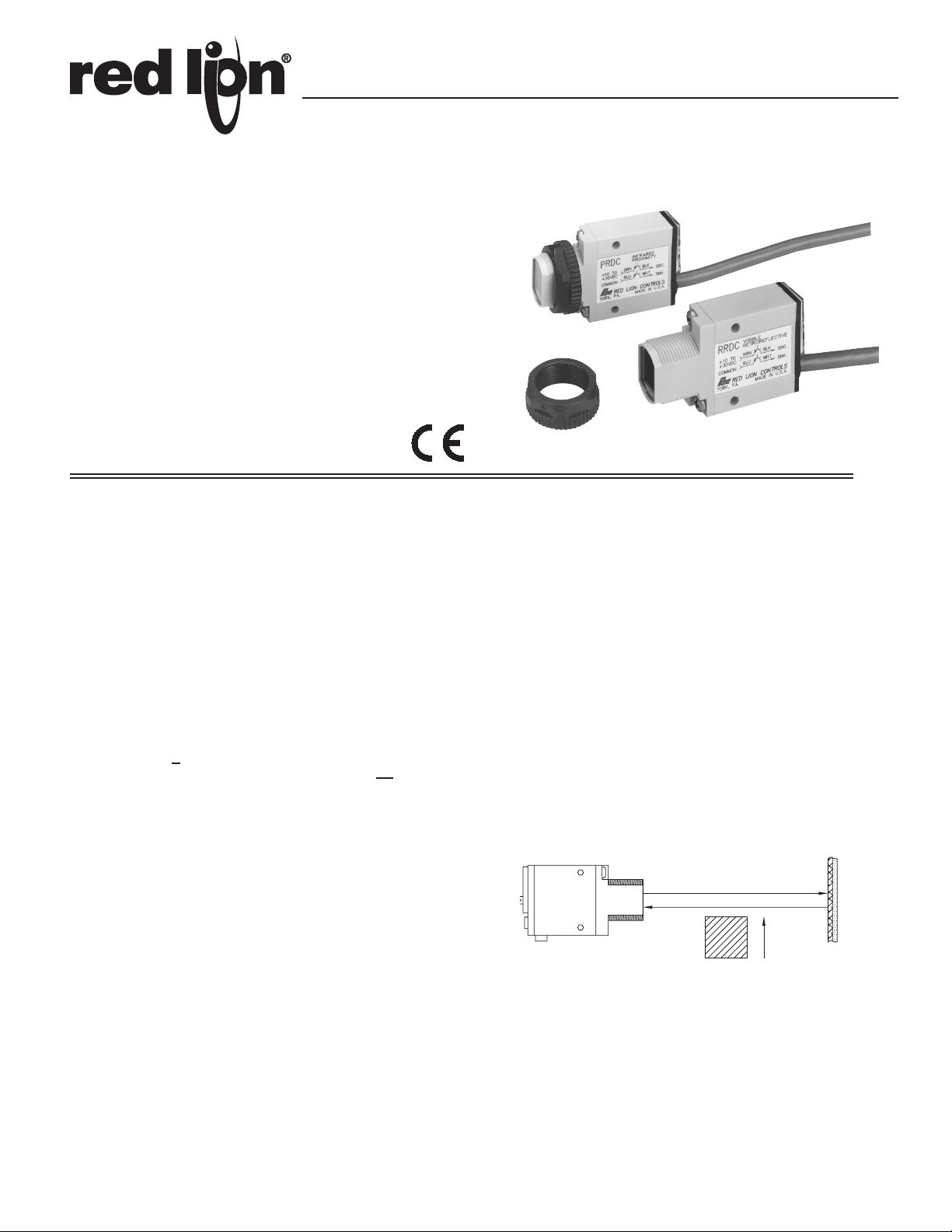
MODEL RRDC - RETROREFLECTIVE SENSOR
The Model RRDC is a compact, DC powered, retroreflective photo-electric
sensor with maximum detection range of 15 feet (with 3" dia. reflector Model
RT2). The “visible” LED light beam allows for easy alignment and is modulated,
providing immunity to ambient light. The small beam size of 1/2" at 1 foot from
the lense, makes it a good choice for detecting relatively small objects.
In operation, the visible LED light beam is directed at a prismatic photo
transistor, amplified and demodulated. An object which then breaks this beam
will trigger the outputs.
RETRO TARGET
RRDC
RETRO-
REFLECTIVE
ALIGNMENT
Apply DC power to the RRDC and direct its visible light beam at a reflective
target (Models RT1 or RT2) while observing the Signal Strength LED on the
back of the unit. Optimum alignment occurs when the sensor is receiving the
maximum amount of reflected light and the GAIN (sensitivity) potentiometer is
adjusted for the highest pulse rate on the Signal Strength LED. Note that glass,
metallic objects, and other highly reflective surfaces may not be detected. In
these applications, mount the sensor and reflector at any angle to the object to
minimize direct reflections.
SENSING RANGE UP TO 15'
OBJECT
1
Page 2
MODEL PRDC - PROXIMITY SENSOR
The Model PRDC is a compact, DC powered, Proximity (Diffuse) photoelectric sensor with a 12" maximum detecting distance (as measured with a
90% reflective white test card). This sensor requires no special reflectors or
reflective tapes and the limited 12" sensing range reduces detection of
background reflections. It is ideally suited for detection of transparent or
translucent objects, parts ejected from presses, and rotating targets such as
pulley spokes. A modulated “infrared” LED light beam provides immunity to
ambient light.
In operation, the modulated light beam is reflected by the object to be
detected. Actual sensing range is determined by the surface area and the
amount of reflectivity of the object. This reflected light is sensed by a phototransistor, amplified, demodulated and then energizes the outputs.
SENSING RANGE UP TO 12"
PRDC
PROXIMITY
OBJECT
ALIGNMENT
With the PRDC in its sensing position, apply DC Power and direct the
infrared light beam at the object to be detected. While observing the Signal
Strength LED, adjust the GAIN (sensitivity) potentiometer for the highest LED
pulse rate. Now remove the sensed object. If the LED goes out, no further
adjustment is necessary. If the LED remains lit, the sensor is “seeing” reflected
light from the background. Reduce the GAIN by steps until the sensor “sees”
the object but not the background. Then turn the pot counter clockwise 2 more
full turns. If the background is still being sensed, it will be necessary to reduce
its reflectivity by either moving it back or painting it flat black.
MODELS EMDC & RCDC - OPPOSED BEAM
EMITTER/ RECEIVER SENSOR PAIR
The Models EMDC (Emitter) and the RCDC (Receiver) are compact, DC
powered, Opposed Beam photo-electric sensor pairs with a 10 foot sensing
range. The Emitter contains a high power modulated “infrared” LED. The
Receiver contains a sensitive photo-transistor, amplifier-demodulator and
output transistors. In operation, these outputs will be triggered when the
Receiver detects that an object begins to break the Emitter beam. Due to their
high gain, they are ideally suited for detecting opaque objects in dirty and dusty
areas or when condensation or oil film environments are present. The small
1/8" well defined beam size allows for sensing small parts accurately and
provides repeatable edge sensing of opaque objects to better than 0.01" for
accurate positioning applications. Greater accuracies can be achieved by
aperturing the Emitter, Receiver or both. However, aperturing will result in
reduced sensing distances. While the beam size is small, the Receiver has a
wide field of view which allows easy “line-of-sight” alignment.
SENSING RANGE UP TO 10'
EMDC
EMITTER
OBJECT
RCDC
RECEIVER
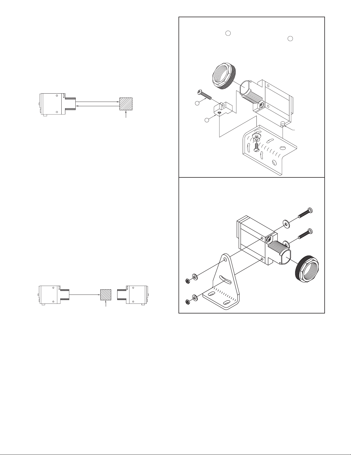
MB2 BOTTOM MOUNT BRACKET KIT INSTALLATION
1. Remove lense mounting nut on sensor and bottom lense screw.
2. Align mounting foot A under lense as shown with threaded insert facing
down and attach to lense with long kit supplied screw B .
3. Place sensor mounting peg into bracket hole.
4. Install screw, with washers, into long slotted bracket hole and into
mounting foot threaded insert.
B
A
MOUNTING
PEG
MB3 SIDE MOUNT BRACKET KIT INSTALLATION
1. Remove lense mounting nut from sensor.
2. Install screws with flat washers, through side clearance holes in sen sor
and through top hole and slot of bracket.
3. Install lockwashers and tighten hex nuts.
ALIGNMENT
Temporarily mount the Emitter-Receiver Pair opposite, and in line-of-sight,
to each other. Apply DC power to both and aim the Emitter at the Receiver.
Move the Receiver up-down-left-right until the Signal Strength LED lights.
Optimum alignment occurs when the Signal Strength LED flashes at the
highest rate obtainable with the GAIN (Sensitivity) potentiometer adjusted to
the lowest setting needed to light the LED. Mount the units in place. Opposed
Beam Pairs should be used at their highest possible gain. Therefore, have the
object to be detected in “sensing position” and adjust the GAIN potentiometer
fully clockwise (maximum gain). If the Signal Strength LED comes on, “burnthrough” is occurring, and will require that the GAIN pot be backed off
(counter clockwise) until the LED goes out and then backed off 2 more full
turns. Note that Opposed Beam Pairs must be aligned properly and mounted
securely. Excessive movement or vibration can cause loss of alignment and
intermittent or false operation.
2
Page 3

MOUNTING OPTIONS
DIMENSIONS In inches (mm)
MB2 BOTTOM MOUNTING BRACKET
MB3 SIDE MOUNTING BRACKET
C
L
0.61 (15.5)
90°
BRACKET
(STAINLESS STEEL)
0.10
(2.5)
0.34
(8.6)
0.47
(11.9)
Ø 0.27
(6.9)
0.34 (8.6)
0.59
(15)
Ø 0.27 (6.9)
0.95
(24.1)
2.00 (50.8)
0.92
(23.4)
R 0.70 (17.8)
R 0.70 (17.8)
ISOMETRIC VIEW
R 0.09 (2.2)
R 0.06 (1.5)
0.48
(12.2)
0.24 (6.2)
R 1.38 (35.1)
R 0.09 (2.2)
R 0.06 (1.5)
0.48
(12.2)
0.24 (6.2)
R 1.38 (35.1)
0.10 (2.5)
#4 MOUNTING
BOLTS (2)
C
L
1.12
(28.5)
90°
BRACKET ROTATES HORIZONTALLY
±10 DEGREES FROM POSITION
0.79
SHOWN
1.79
(45.5)
BRACKET
(STAINLESS STEEL)
(20.1)
FRONT OF SENSOR
TILTS VERTICALLY
±15 DEGREES
FROM HORIZONTAL
1.59
(40.4)
0.40
(10.2)
4X R 0.09
(2.2)
30.0°
1.25
(31.8)
ISOMETRIC VIEW
Ø 0.12
(3.0)
2X R 0.06
(1.5)
R 0.40
(10.2)
R 0.48
(12.1)
TYPICAL HOOKUP
DC
PHOTO ELECTRIC
CONTROLLER
BRN (+10 TO 30VDC)
BLK (PNP O.C.)
WHT (NPN O.C.)
BLUE (COMMON)
REMOTE
CUB
H.S. CNT.
L.S. CNT.
RMT. RST.
RST. EN.
COMMON
TYPICAL COUNTER
INPUT SWITCH SET-UP
A
+12V
COMM.
B
C
CNT.
SRC.
*
SNK.
LO FRQ.
321
HI
LO BIAS
* APPLICATION
HI
DEPENDENT
3
Page 4

DIMENSIONS In inches (mm)
.
48
FRONT REAR
VIEW VIEW
GAIN CONTROL
C
L
.61
(15.5)
.48
(12.2)
SIDE
VIEW
6' PVC-COVERED
4-CONDUCTOR CABLE
BROWN (+10 TO 30VDC)
BLACK (PNP SOURCING OUTPUT)
WHITE (NPN SINKING OUTPUT)
BLUE (COMMON)
(CIRCULAR, .25 (6.3) DIA.)
1.21
(30.7)
MOUNTING HOLES (2), #4 SCREW
CLEARANCE; USE FOR SIDE MOUNTING
GASKETED
ACRYLIC
COVER
MOUNTING PEG
.95
(24.1)
1.5 (38.1)
SIGNAL STRENGTH LED INDICATOR
LIGHT/DARK OPERATE SWITCH
1.08 (27.4)
.125
(3.2)
18 x 1 MM
THREAD
2.1 (53.3)
CABLE
.71
(18)
DIA.
(12.2)
+
-
D.O.
L.O.
.10 (2.5)
MOUNTING NUT
(SUPPLIED)
.95
(24.1)
.32 (8.1)
EMDC HOOKUP
BROWN
(+10 TO 30VDC)
BLUE (COMMON)
1. GAIN (sensitivity) control: rotate clockwise to increase gain.
2. “SIGNAL STRENGTH” LED indicator pulse at a rate proportional to received light signal
strength.
3. LIGHT/DARK OPERATE SELECT control: DARK OPERATE = fully counter clockwise;
LIGHT OPERATE = fully clockwise.
4. 6´ PVC-jacketed 4-wire cable supplied (2-wire, EMDC).
ORDERING INFORMATION
MODEL NO. DESCRIPTION PART NUMBERS
RRDC Retroreflective DC Photo-Electric Sensor RRDC0000
PRDC Proximity (Diffuse) DC Photo-Electric Sensor PRDC0000
EMDC DC Emitter (Opposed Beam Pair) EMDC0000
RCDC DC Receiver (Opposed Beam Pair) RCDC0000
MB2 Bottom Mount Bracket Kit MB200000
MB3 Side Mount Bracket Kit MB300000
RT1 1-1/2" Dia. Prismatic Reflector (Model RRDC) RT100000
RT2 3" Dia. Prismatic Reflector (Model RRDC) RT200000
Do not dispose of unit in trash - Recycle
Red Lion Controls
Headquarters
20 Willow Springs Circle
York PA 17406
Tel +1 (717) 767-6511
Fax +1 (717) 764-0839
Red Lion Controls
Europe
Softwareweg 9
NL - 3821 BN Amersfoort
Tel +31 (0) 334 723 225
Fax +31 (0) 334 893 793
Red Lion Controls
India
201-B, 2nd Floor, Park Centra
Opp 32 Mile Stone, Sector-30
Gurgaon-122002 Haryana, India
Tel +91 984 487 0503
Red Lion Controls
China
Unit 302, XinAn Plaza
Building 13, No.99 Tianzhou Road
ShangHai, P.R. China 200223
Tel +86 21 6113 3688
Fax +86 21 6113 3683
 Loading...