

Page 1

Inside US: +1 (877) 432-9908 Bulletin No. DA30D-A
FOR USE IN HAZARDOUS LOCATIONS:
Class I, Division 2, Groups A, B, C, and D
C
US
U
L
R
LISTED
IND.CONT. EQ.
5.03
(127.7)
3.99 (101.4) 1.31 (33.3)
WARNING - EXPLOSION HAZARD - DO NOT D
EQUIPMENT UNLESS POWER HAS BEEN SW
OR AREA IS KNOWN TO BE NON-HAZARDOU
CAUTION: Risk of Danger.
Read complete instructions prior to installation
and operation of the unit.
WARNING - EXPLOSION HAZARD - DO NOT DISCONNECT
EQUIPMENT UNLESS POWER HAS BEEN SWITCHED OFF
OR AREA IS KNOWN TO BE NON-HAZARDOUS.
WARNING - EXPLOSION HAZARD - DO NOT DISCONNECT
EQUIPMENT UNLESS POWER HAS BEEN SWITCHED OFF
OR AREA IS KNOWN TO BE NON-HAZARDOUS.
WARNING - EXPLOSION HAZARD - SUBSTITUTION OF
COMPONENTS MAY IMPAIR SUITABILITY FOR CLASS I,
DIVISION 2.
Outside US: +1 (717) 767-6511 Drawing No. LP1078
www.redlion.net Effective 2018-11-02
ModelDA30D‐HighPerformanceProtoc olConverterandDataAcquisition
System
• CONFIGURED USING CRIMSON
®
3.1 SOFTWARE
• THREE SERIAL COMMUNICATION PORTS,
(2 RS-232 and 1 RS-422/485)
• A 10 BASE T/100 BASE-TX ETHERNET PORT COMMUNICATES
WITH UP TO TEN PROTOCOLS SIMULTANEOUSLY
• ACCEPTS ONE EXPANSION COMMUNICATION MODULE TO ADD
CANOPEN, J1939, PROFIBUS, DEVICENET AND MORE
• ONE USB DEVICE PORT TO LOAD THE UNIT’S CONFIGURATION
OR TRANSFER DATA TO AND FROM A PC
• SD CARD SOCKET FOR DATA LOGGING AND LOADING DATABASE
IN FIELD
• RUGGED IP40-RATED ENCLOSURE
• THREE FRONT FACE LED INDICATORS
• POWER UNIT FROM 10-30 VDC SUPPLY
• SUPPORTS OVER 300 INDUSTRIAL PROTOCOLS
• BUILT-IN WEB SERVER FOR REMOTE ACCESS
• REAL-TIME DATA LOGGING
• ALARM NOTIFICATIONS VIA EMAIL OR SMS MESSAGES
GENERALDESCRIPTION
The DA30D data station acts as a nexus for industrial data collection
and management. The unit offers multiple protocol conversion, data
logging and remote machine access. With three built in serial ports and a
10 Base-T/100 Base-TX Ethernet port, the unit performs protocol
conversion, allowing disparate devices to communicate seamlessly with
one another including PLCs, motor drives, bar code scanners, etc. The
Ethernet port supports up to ten protocols simultaneously using Crimson
3.1, so even Ethernet to Ethernet protocols can be converted.
The SD card slot can collect your trending and datalogging information
as well as load the unit's configuration file, allowing configuration
changes to be made and saved to the card for later transfer.
The built-in web server allows log files to be retrieved manually, and
also provides access to the unique “virtual HMI”. The virtual HMI is
programmed just like Red Lion’s CR3000 series of HMIs. Any standard
web browser may be used to monitor or control the DA30D from a PC
anywhere in the world.
The DAx0D is programmed with Red Lion's Crimson 3.1 software.
Crimson offers easy to use drag and drop communications configuration
and is available as a no charge download from Red Lion's website.
E317425
SAFETYSUMMARY
All safety related regulations, local codes and instructions that appear
in the manual or on equipment must be observed to ensure personal
safety and to prevent damage to either the instrument or equipment
connected to it. If equipment is used in a manner not specified by the
manufacturer, the protection provided by the equipment may be
impaired.
Do not use the unit to directly command motors, valves, or other
actuators not equipped with safeguards. To do so can be potentially
harmful to persons or equipment in the event of a fault to the unit.
DIMENSIONSIninches(mm)
CONTENTSOFPACK AGE
- DA30D
- Terminal block for connecting power
ORDERINGINFORMATION
MODEL NO. DESCRIPTION PART NUMBER
DA30D
CRM000
CBL
CRA000 Replacement Battery CRA000 BT3V0 00000
1
Contact your Red Lion distributor or visit our website for selection of expansion
modules, SD
-1-
Protocol Converter with 3 Serial Ports,
1 Ethernet Port, and USB Device Port
Expansion Modules
SD
1
SD Card
Communications Cables and Adapter
cards, adapters and cables.
1
DA30D 0F 000000 000
CRM0000 xxxxx xxxxx
SDxxxxxx
1
CBLxxxxx
Page 2
Bulletin No. DA30D-A Effective 2018-11-02
ROTATE
1.00"
1.00"
min. clearance
min. clearance
TOP
Drawing No. LP1078
SPECIFICATIONS
1. POWER REQUIREMENTS:
Must use a Class 2 circuit according to National Electrical Code (NEC),
NFPA-70 or Canadian Electrical Code (CEC), Part I, C22.1 or a
Limited Power Supply (LPS) according to IEC 60950-1 or Limitedenergy circuit according to IEC 61010-1.
Power connection via removable three position terminal block.
Supply Voltage: 10 to 30 VDC, Class 2 source
Input Voltage (Volts) 10 V 12 V 24 V 30 V
Typ. Power DA30D only (Watts) 4.5 5.0 5.0 5.0
Max Power DA30D only (Watts) 6.5 7.0 7.0 7.0
Max Power DA30D w/Module (W) 11.5 12.5 12.5 12.5
2. BATTERY: Lithium coin cell. Typical lifetime of 5 years, nominal.
To maintain UL rating, replacement battery must be: Red Lion CRA000
BT3V0 00000, Rayovac BR1225X-BA or Panasonic BR1225A/BN.
3. MEMORY:
On Board User Memory: 512 Mbyte of non-volatile Flash memory.
Memory Card: SD slot accepts standard capacity cards up to 16 GB.
4. COMMUNICATION CAPABILITIES:
USB Device Port: Isolated and adheres to USB specification 2.0 full
speed only using Type B connection.
SYSTEM SET-UP AND DIAGNOSTICS AND IS NOT INTENDED FOR
PERMANENT CONNECTION.
USB Host Port: Comply with Universal Serial Bus Specification Rev
2.0. Support data transfers at (high speed, full speed). Hardware
over current protected (0.5 A max per port).
Serial Ports: Ports are individually isolated. Format and Baud Rates for
each port are individually software programmable up to 115,200
baud.
Port to Port Isolation: 1500 Vrms for 1 minute.
Signal Isolation: 500 V.
USB DEVICE PORT IS FOR
Ethernet Port: 10 BASE-T / 100 BASE-TX
RJ45 jack is wired as a NIC (Network Interface Card).
Isolation from Ethernet network to operator interface: 1500 Vrms
5. ENVIRONMENTAL CONDITIONS:
Operating Temperature Range: -10 to 50 °C
Storage Temperature Range: -20 to 70 °C
Vibration to IEC 68-2-6: Operational 5-500 Hz, 2 g
Shock to IEC 68-2-27: Operational 30 g
Operating and Storage Humidity: 0 to 85% max. RH non-condensing
Altitude: Up to 2000 meters
Installation Category II, Pollution Degree 2 as defined in IEC/EN 60664-1.
6. CERTIFICATIONS AND COMPLIANCES:
CE Approved
EN 61326-1 Immunity to Industrial Locations
Emission CISPR 11 Class A
IEC/EN 61010-1
RoHS Compliant
UL Hazardous: File #E317425
Rugged IP40 enclosure
7. CONNECTIONS: High compression cage-clamp terminal block
Wire Strip Length: 0.3" (7.5 mm)
Wire Gage Capacity: 12 to 24 AWG (3.31 to 0.20 mm
Torque: 4.4-5.3 inch-lbs (0.5-0.6 N-m)
8. CONSTRUCTION: Polycarbonate enclosure with IP40 rating. For
indoor use only.
9. MOUNTING REQUIREMENTS: Snaps onto standard DIN style top hat
(T) profile mounting rails according to EN50022 – 35 x 7.5 mm and
35 x 15 mm.
10. WEIGHT: 6.9 oz (195.61 g)
2
) copper wire
INSTALLINGANDPOWERINGTHEDA30D
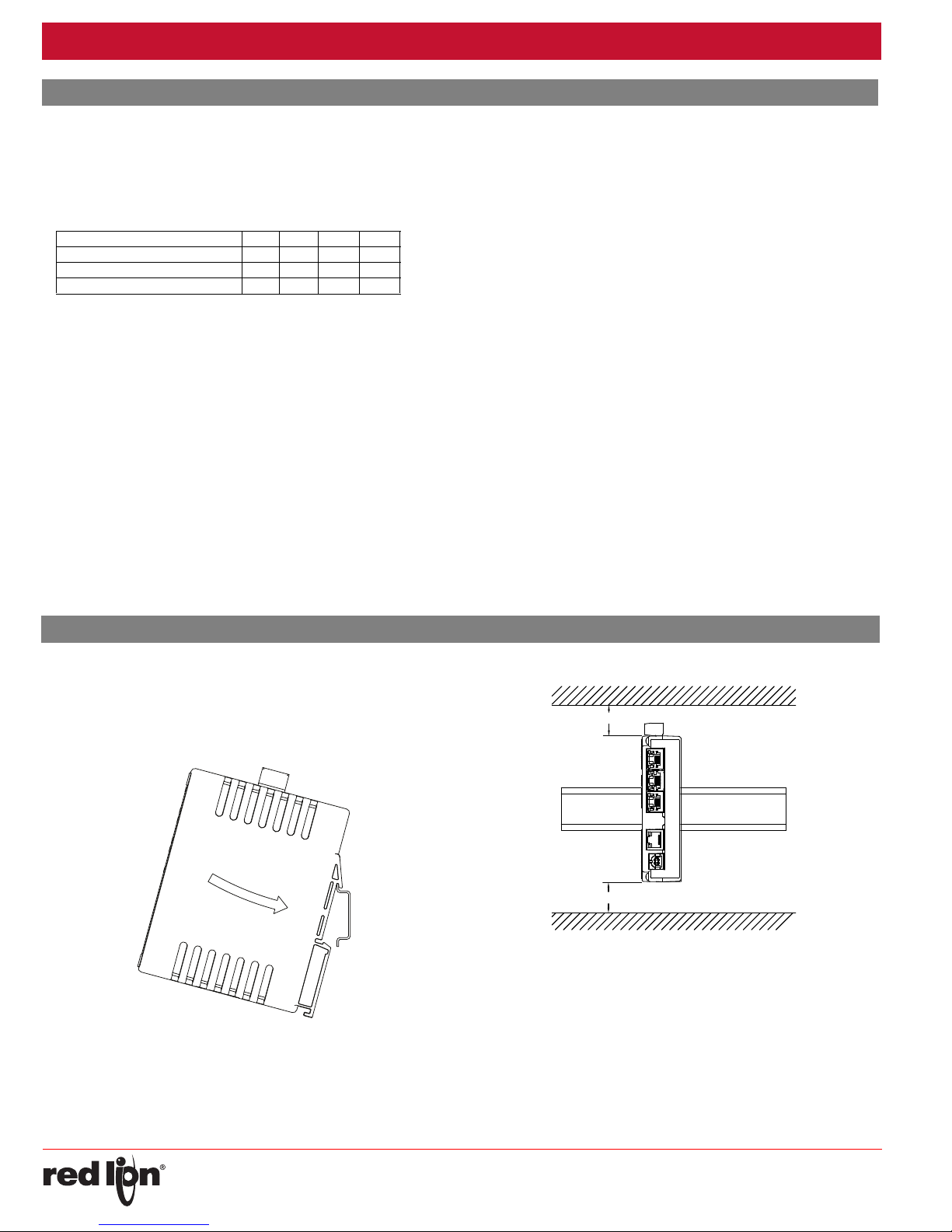
MOUNTINGINSTRUCTIONS
DIN rail should be mounted horizontally so that the unit’s ventilation
holes are vertical in relation to cabinet orientation. A minimum clearance
of 1 inch (25.4 mm) should be maintained above and below the unit in
order to ensure proper thermal regulation.
Figure 1 - Attach DAx0D To DIN Rail
The unit shall be installed inside a UL Listed Industrial Control Panel or
similar type of enclosure. A minimum 3.2 mm distance shall be
maintained between the hazardous live parts of the equipment and
accessible parts of the fire/electrical enclosure.
BOTTOM
For hazardous location installation the following shall be taken into
consideration:
- This device is open-type and must be mounted in a suitable dust-
tight end-enclosure in accordance with articles 500 and 502 of the
National Electric Code (NEC).
- Must be wired using Division 2 wiring methods as specified in article
501-4(b), 502-4(b), and 503-3(b) of the NEC, NFPA 70 for
installation within the United States, or as specified in section 19-152
of Canadian Electrical Code for installation in Canada.
- Combinations of equipment in your system are subject to investigation
by the local Authority having jurisdiction at the time of installation.
-2-
Page 3

Effective 2018-11-02 Bulletin No. DA30D-A
REMOVE MODULE PLUG
WARNING: Disconnect all power
to the unit before installing or
removing modules.
Drawing No. LP1078
CONNECTING POWER
The DA30D requires a 10-30 VDC power
supply. A pluggable power block is provided
to connect the 24 VDC. There are three screw
terminals. Strip and connect the wire
according to the terminal block specifications
on Page 2. Connect the positive lead to the
plus (+) screw and the negative lead to the
minus (-) screw.
Please take care to observe the following points:
– Mount the power supply close to the unit, with usually not more than
6 feet (1.8 m) of cable between the supply and the operator
interface. Ideally, the shortest length possible should be used.
– The wire used to connect the operator interface’s power supply
should be at least 22-gage wire suitably rated for the temperatures
of the environment to which it is being installed. If a longer cable run
is used, a heavier gage wire should be used. The routing of the
cable should be kept away from large contactors, inverters, and
other devices which may generate significant electrical noise.
– A power supply with an NEC Class 2 or Limited Power Source (LPS)
and SELV rating is to be used. This type of power supply provides
isolation to accessible circuits from hazardous voltage levels generated
by a mains power supply due to single faults. SELV is an acronym for
“safety extra-low voltage.” Safety extra-low voltage circuits shall exhibit
voltages safe to touch both under normal operating conditions and after
a single fault, such as a breakdown of a layer of basic insulation or after
the failure of a single component has occurred. A suitable disconnect
device shall be provided by the end user.
CONNECTING TO EARTH GROUND
The third pin of the power connector is chassis ground for the unit.
Your unit should be connected to earth ground. Steps should be taken
beyond connecting to earth ground to eliminate the buildup of
electrostatic charges.
The chassis ground is not connected to signal common of the unit.
Maintaining isolation between earth ground and signal common is not
required to operate your unit. But, other equipment connected to this unit
may require isolation between signal common and earth ground. To
maintain isolation between signal common and earth ground care must
be taken when connections are made to the unit. For example, a power
supply with isolation between its signal common and earth ground must
be used. Also, plugging in a USB cable may connect signal common and
earth ground.
1
USB’s shield may be connected to earth ground at the host. USB’s
shield in turn may also be connected to signal common.
1
MODULEINSTALLATION
Remove module plug and attach module to DA30D. Torque screws to
6.0 pound-force inch [96 ounce-force inch] (0.68 Nm).
EMCINSTALLATIONGUIDELINES
Although Red Lion Controls products are designed with a high degree
of immunity to Electromagnetic Interference (EMI), proper installation and
wiring methods must be followed to ensure compatibility in each
application. The type of the electrical noise, source or coupling method
into a unit may be different for various installations. Cable length, routing,
and shield termination are very important and can mean the difference
between a successful or troublesome installation. Listed are some EMI
guidelines for a successful installation in an industrial environment.
1. A unit should be mounted in a metal enclosure, which is properly
connected to protective earth.
2. Use shielded cables for all Signal and Control inputs. The shield
connection should be made as short as possible. The connection point
for the shield depends somewhat upon the application. Listed below
are the recommended methods of connecting the shield, in order of
their effectiveness.
a. Connect the shield to earth ground (protective earth) at one end
where the unit is mounted.
b. Connect the shield to earth ground at both ends of the cable, usually
when the noise source frequency is over 1 MHz.
3. Never run Signal or Control cables in the same conduit or raceway with
AC power lines, conductors, feeding motors, solenoids, SCR controls,
and heaters, etc. The cables should be run through metal conduit that
is properly grounded. This is especially useful in applications where
cable runs are long and portable two-way radios are used in close
proximity or if the installation is near a commercial radio transmitter.
Also, Signal or Control cables within an enclosure should be routed as
far away as possible from contactors, control relays, transformers, and
other noisy components.
4. Long cable runs are more susceptible to EMI pickup than short cable runs.
5. In extremely high EMI environments, the use of external EMI
suppression devices such as Ferrite Suppression Cores for signal and
control cables is effective. The following EMI suppression devices (or
equivalent) are recommended:
Fair-Rite part number 0443167251 (Red Lion Controls #FCOR0000)
Line Filters for input power cables:
Schaffner # FN2010-1/07 (Red Lion Controls #LFIL0000)
6. To protect relay contacts that control inductive loads and to minimize
radiated and conducted noise (EMI), some type of contact protection
network is normally installed across the load, the contacts or both. The
most effective location is across the load.
a. Using a snubber, which is a resistor-capacitor (RC) network or metal
oxide varistor (MOV) across an AC inductive load is very effective at
reducing EMI and increasing relay contact life.
b. If a DC inductive load (such as a DC relay coil) is controlled by a
transistor switch, care must be taken not to exceed the breakdown
voltage of the transistor when the load is switched. One of the most
effective ways is to place a diode across the inductive load. Most
Red Lion products with solid state outputs have internal zener diode
protection. However external diode protection at the load is always a
good design practice to limit EMI. Although the use of a snubber or
varistor could be used.
Red Lion part numbers: Snubber: SNUB0000
7. Care should be taken when connecting input and output devices to the
instrument. When a separate input and output common is provided,
they should not be mixed. Therefore a sensor common should NOT be
connected to an output common. This would cause EMI on the
sensitive input common, which could affect the instrument’s operation.
Visit www.redlion.net/emi
Safety and CE issues as they relate to Red Lion products.
Varistor: ILS11500 or ILS23000
for more information on EMI guidelines,
-3-
Page 4

Bulletin No. DA30D-A Effective 2018-11-02
DA30D PORT PIN OUTS
COMM
(PGM)
TxB (PIN 1)
TxA
RxB
RxA
TxEN
TxA (PIN 8)
TxB
COMM
RTS (PIN 6)
Tx
COMM
COMM
Tx
Rx
CTS (PIN 1)
RTS (PIN 6)
ETHERNET
(NIC)
TYPE B
USB
RS485/422
RS232
CTS (PIN 1)
COMM
Rx
RS232
USB
TYPE A
SD STATUS (BLUE)
POWER (GREEN)
ALARM (RED)
FRONT PANEL LEDS
WARNING - DO NOT CONNECT OR DISCONNECT CABLES
WHILE POWER IS APPLIED UNLESS AREA IS KNOWN TO BE
NON-HAZARDOUS. USB DEVICE PORT IS FOR SYSTEM SET-UP
AND DIAGNOSTICS AND IS NOT INTENDED FOR PERMANENT
CONNECTION.
DAX0D RS232 TO A PC
DAx0D: RJ12 Name PC: DB9 Name
4COMM1DCD
5Tx2Rx
2Rx3Tx
N/C 4 DTR
3COMM5GND
N/C 6 DSR
1CTS7RTS
6RTS8CTS
N/C 9 RI
Drawing No. LP1078
COMMUNICATINGWITHTHEDA30D
CONFIGURINGADA30D
The DA30D is configured using Crimson® 3.1 software. Crimson is
available as a no charge download from Red Lion’s website. Crimson
updates for new features and drivers are posted on the website as they
become available. By configuring the DA30D using the latest Crimson
version, you are assured that your unit has the most up to date feature
set. Crimson software can configure the DA30D through the RS232 PGM
port, USB port, Ethernet port or SD card.
The DA30D has three serial ports, a USB device port, one USB Host
port, and an Ethernet port as shown below.
The serial ports are available via RJ connectors. There are two RS232
ports. The port labeled RS232 (PGM) can be used as a Programming
Port or you can assign a protocol to it. The RS485 port can be used for
both RS485 or 422 communications. All of the serial ports are isolated.
The Ethernet port can be programmed to communicate via ten
protocols simultaneously. For more information on protocol support,
please refer to the Crimson 3.1 User Manual.
The USB device port is a standard device port with a Type B connector,
and is used as the programming port. The driver needed to use the USB
port will be installed with
The USB host port is a standard host port with a Type A connector
can be used to interface to USB enabled peripherals. This port
5 V power per the USB standard.
The SD card can be used to program a DA30D by placing a database
image file on the SD card. The card is then inserted into the target DA30D
and powered. Refer to the Crimson 3.1 User Manual for more information
on the naming convention and location for this file.
Crimson.
supplies
and
INSERTION/REMOVALOFTHESDCARD
Insert the SD card into the slot provided with the card oriented as shown.
The card is inserted properly when the end of the card is flush with the
DA30D case. To remove the SD card, push in slightly on the card.
CABLESANDDRIVERS
Red Lion has a wide range of cables and drivers for use with many
different communication types. A list of these drivers and cables along
with pin outs is available from Red Lion’s website. New cables and
drivers are added on a regular basis. If making your own cable, refer to
the “Port Pin Outs” that corresponds to your specific model for wiring
information.
ETHERNETCOMMUNICATIONS
Ethernet communications can be established at either 10 BASE-T or
100 BASE-TX. The unit’s RJ45 jack is wired as a NIC (Network Interface
Card). It auto-detects remote transmit and receive pairs and correctly
assigns the transmit and receive pairs. This feature enables the user to
use whichever type of cable (cross-over or straight) is available.
The Ethernet connector contains two LEDs. A yellow LED in the upper
right, and a green LED in the upper left. The LEDs represent the following
statuses:
LED COLOR DESCRIPTION
YELLOW solid Link established.
YELLOW flashing Data being transferred.
GREEN (OFF) 10 BASE-T Communications
GREEN (ON) 100 BASE-TX Communications
On the rear of each unit is a unique 12-digit MAC address. Refer to the
Crimson manual and Red Lion’s website for additional information on
Ethernet communications.
USB,DA TATRANSFERSFROMTHESDCARD
must be installed on your computer. This driver is installed with Crimson
and is located in the folder C:\Program Files\Red Lion Controls\Crimson
3.1\Device\ after Crimson is installed. This may have already been
accomplished if your DAx0D was configured using the USB port.
cable, and refer to the “Mounting the SD Card” section in the Crimson 3.1
User Manual.
In order to transfer data from the SD card via the USB port, a driver
Once the driver is installed, connect the DAx0D to your PC with a USB
RS232PORTS
The DA30D has two
RS232 serial ports. Although
only one of these ports can
be used for programming,
both ports can be used for
communications with a PLC.
The serial ports can be used
for either master or slave
protocols with any DA30D
configuration. Each serial
port has a pair of LEDs to
indicate transmit and receive
activity. The pinouts are
shown to the right.
-4-
Page 5

Effective 2018-11-02 Bulletin No. DA30D-A
TX
5V
8
1
7
2
TxB
TxA
130K
130K
5
TxEN (OC)
RX
130K
5V
130K
RxB
4
RxA
3
COMM
6
RS422/485 4-WIRE
CONNECTIONS
RS485 2-WIRE
CONNECTIONS
TxEN (OC)
TX/RX
130K
5
TxA
2
8
130K
5V
7
1
TxB
6 COMM
DAX0D TO RED LION RJ11
DAx0D:RJ45 Name RLC:RJ11 Name
5TxEN2TxEN
6COMM3COMM
1 TxB 5 B-
2 TxA 4 A+
DAX0D TO RED LION RJ45
DAx0D Name RLC:RJ45 Name
1,4 TxB 1,4 TxB
4,1 RxB 4,1 RxB
2,3 TxA 2,3 TxA
3,2 RxA 3,2 RxA
5TxEN 5 TxEN
6COMM 6 COMM
7 TxB 7 TxB
8 TxA 8 TxA
Drawing No. LP1078
RS422/485COMMSPORT
The RS485 port of the DA30D can be used for RS485 or RS422
communication. There is a separate RJ connector for each option. Each
serial port has a pair of LEDs to indicate transmit and receive activity.
Note: All Red Lion devices connect A to A and B to B. Refer to
www.redlion.net for additional information.
ExamplesofRS4852‐WireConnections
DH485COMMUNICATIONS
The DA30D’s RS422/485 COMMS port can also be used for Allen
Bradley DH485 communications.
WARNING: DO NOT use a standard DH485 cable to connect this port to
Allen Bradley equipment. A cable and wiring diagram are available
from Red Lion at www.redlion.net/cables-drivers
.
SOFTWARE/UNITOPERATION
CRIMSON®3.1SOFTWARE
Crimson 3.1 software is available as a no charge download from Red
Lion’s website. The latest version of the software is always available from
the website, and updating your copy is free.
STATUSLEDS
There are three status LEDs that show system status by default, or they
may be be user configured via System Functions using Crimson 3.1.
Shown below is the default system status of the LEDs.
LED INDICATION
GREEN
STEADY Unit is powered.
BLUE
FLASHING
OFF No SD card is present.
STEADY Valid SD card present.
FLASHING RAPIDLY SD card being checked.
FLICKERING SD card accessed.
FLASHING SLOWLY Incorrectly formatted SD card present.
RED
FLASHING Data tag is in an alarm active state.
STEADY Data tag is in an alarm accepted state.
Unit is in the boot loader
FACTORYRESETBUTTON
The factory reset button located on the bottom of the unit enclosure
near the SD card slot can be used to access the system console. Refer to
Crimson 3 System Console Technical Note at w
ww.redlion.net/TNIA22 for
access procedure and available options.
TROUBLESHOOTINGYOURDAx0D
If for any reason you have trouble operating, connecting, or simply have
questions concerning your new DAx0D unit, contact Red Lion’s technical
support.
Email: support@redlion.net
Website: www.redlion.net
Inside US: +1 (877) 432-9908
Outside US: +1 (717) 767-6511
-5-
Page 6

Bulletin No. DA30D-A Effective 2018-11-02
WARNING - EXPLOSION HAZARD - DISCONNECT POWER AND
ENSURE THE AREAS IS KNOWN TO BE NON-HAZARDOUS
BEFORE SERVICING/REPLACING THE UNIT AND BEFORE
INSTALLING OR REMOVING I/O WIRING AND BATTERY.
+
-
To maintain UL rating, battery must
be replaced with one listed in the
Specifications.
Drawing No. LP1078
BATTERY&TIMEKEEPING
A battery is used to keep time when the unit is without power. The
battery of a DAx0D unit does not affect the unit’s memory, all
configurations and data is stored in non-volatile memory.
ChangingtheBattery
To change the battery of a DAx0D, first remove power to the unit.
Remove the SD card if one is installed. Insert a small screwdriver into the
slot provided on the battery holder and pry the battery holder with battery
out of the unit. Remove the old battery from the plastic holder and replace
it with a new battery. Make sure the orientation of the battery is correct
and as shown in the diagram.
Re-install the battery holder with battery into the DAx0D unit. Enter
new date and time using Crimson 3.1 software.
CAUTION: Lithium battery. Danger of explosion if battery is
incorrectly replaced. Replace only with the same or equivalent
type recommended by the manufacturer.
Please note that the old battery must be disposed of in a
manner that complies with your local waste regulations. The
battery must not be disposed of in fire, or in a manner whereby
it may be damaged and its contents could come into contact
with human skin.
-6-
Page 7

Effective 2018-11-02 Bulletin No. DA30D-A
Drawing No. LP1078
This page intentionally left blank
-7-
Page 8

Bulletin No. DA30D-A Effective 2018-11-02
LIMITED WARRANTY
(a) Red Lion Controls Inc., (the “Company”) warrants that all Products shall be free from defects in material and
workmanship under normal use for the period of time provided in “Statement of Warranty Periods” (available at
www.redlion.net) current at the time of shipment of the Products (the “Warranty Period”). EXCEPT FOR THE ABOVE-
STATED WARRANTY, COMPANY MAKES NO WARRANTY WHATSOEVER WITH RESPECT TO THE
PRODUCTS, INCLUDING ANY (A) WARRANTY OF MERCHANTABILITY; (B) WARRANTY OF FITNESS FOR A
PARTICULAR PURPOSE; OR (C) WARRANTY AGAINST INFRINGEMENT OF INTELLECTUAL PROPERTY
RIGHTS OF A THIRD PARTY; WHETHER EXPRESS OR IMPLIED BY LAW, COURSE OF DEALING, COURSE OF
PERFORMANCE, USAGE OF TRADE OR OTHERWISE. Customer shall be responsible for determining that a
Product is suitable for Customer’s use and that such use complies with any applicable local, state or federal law.
(b) The Company shall not be liable for a breach of the warranty set forth in paragraph (a) if (i) the defect is a result
of Customer’s failure to store, install, commission or maintain the Product according to specifications; (ii) Customer
alters or repairs such Product without the prior written consent of Company.
(c) Subject to paragraph (b), with respect to any such Product during the Warranty Period, Company shall, in its
sole discretion, either (i) repair or replace the Product; or (ii) credit or refund the price of Product provided that, if
Company so requests, Customer shall, at Company’s expense, return such Product to Company.
(d) THE REMEDIES SET FORTH IN PARAGRAPH (c) SHALL BE THE CUSTOMER’S SOLE AND EXCLUSIVE
REMEDY AND COMPANY’S ENTIRE LIABILITY FOR ANY BREACH OF THE LIMITED WARRANTY SET FORTH
IN PARAGRAPH (a).
Drawing No. LP1078
TRADEMARKACKNOWLEDGMENTS
Ethernet is a registered trademark of Xerox Corporation.
All other company and product names are trademarks of their
respective owners.
-8-
 Loading...