

Page 1
1
DESCRIPTION
This bulletin serves as a guide for the installation, configuration and operation
of the RS232 and RS485 serial communications plug-in cards for the CUB5.
The plug-in cards are separately purchased option cards that plug into the main
circuit board of the meter. Only one communication card can be used at a time.
Crimson is a Windows®based program that allows configuration of the CUB5
meters from a PC. Crimson offers standard drop-down menu commands, that
make it easy to program the CUB5 meters. The CUB5 program can then be
saved in a PC file for future use. A CUB5 serial plug-in card is required to
program the meter using the software.
MODEL CUB5COM -SERIAL COMMUNICATIONS PLUG-IN OPTION CARDS
Bulletin No. CUB5COM-B
Drawing No. LP0606
Released 1/08
Tel +1 (717) 767-6511
Fax +1 (717) 764-0839
www.redlion.net
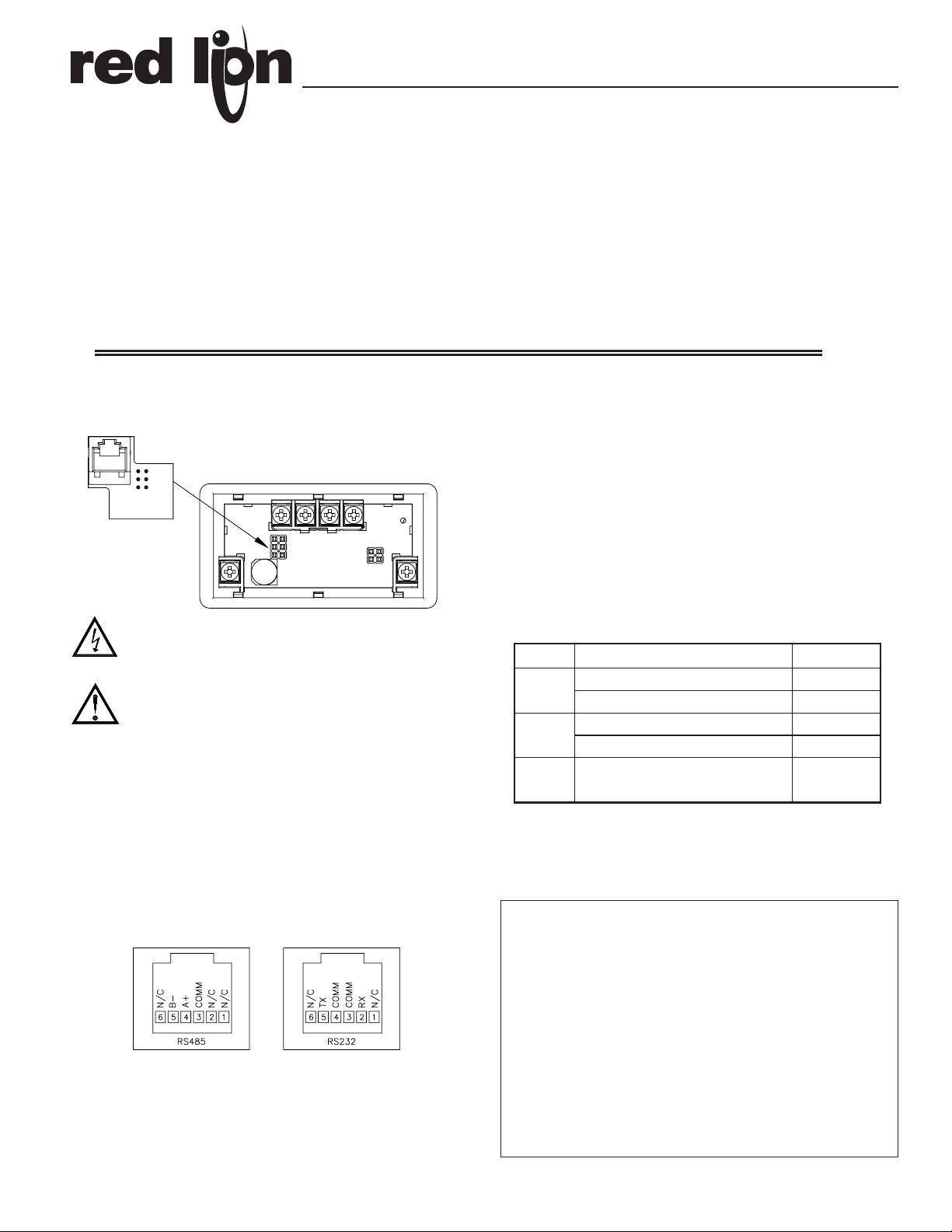
INSTALLING PLUG-IN CARDS
The cards plug into the main circuit board of the meter as shown.
WARNING: Disconnect all power to the unit before
installing Plug-in card.
CAUTION: The Plug-in cards and main circuit board contain static
sensitive components. Before handling the cards, discharge static
charges from your body by touching a grounded bare metal
object. Ideally, handle the cards at a static controlled clean
workstation. Also, only handle the cards by the edges. Dirt, oil or
other contaminants that may contact the cards can adversely
affect circuit operation.
WIRING CONNECTIONS
Connections to the serial communications cards are made through an RJ11
modular connector. Connector pin-outs for the RS485 and RS232 cards are
shown below.
SPECIFICATIONS
RS485 SERIAL COMMUNICATIONS CARD
Type: RS485 multi-point balanced interface (non-isolated)
Baud Rate: 300 to 38.4k
Data Format: 7/8 bits; odd, even, or no parity
Bus Address: 0 to 99; max 32 meters per line
Transmit Delay: Selectable, 2 msec min. or 50 msec min.
RS232 SERIAL COMMUNICATIONS CARD
Type: RS232 half duplex (non-isolated)
Baud Rate: 300 to 38.4k
Data Format: 7/8 bits; odd, even, or no parity
ORDERING INFORMATION
* Crimson software is available for download from http://www.redlion.net/
Comms Card
RJ11 CONNECTOR PIN OUTS
MODEL NO. DESCRIPTION PART NUMBER
SFCRD*
CBL
CUB5COM
Crimson 2 PC Configuration Software for
Windows 98, ME, 2000 and XP
RS232 Programming Cable (DB9-RJ11)
RS485 Serial Communications Card
SFCRD200
CBLPROG0
CUB5COM1
RS485 Programming Cable (DB9-RJ11)
RS232 Serial Communications Card
CBPRO007
CUB5COM2
LIMITED WARRANTY
The Company warrants the products it manufactures against defects in materials and
workmanship for a period limited to two years from the date of shipment, provided the
products have been stored, handled, installed, and used under proper conditions. The
Company’s liability under this limited warranty shall extend only to the repair or
replacement of a defective product, at The Company’s option. The Company disclaims
all liability for any affirmation, promise or representation with respect to the products.
The customer agrees to hold Red Lion Controls harmless from, defend, and indemnify
RLC against damages, claims, and expenses arising out of subsequent sales of RLC
products or products containing components manufactured by RLC and based upon
personal injuries, deaths, property damage, lost profits, and other matters which Buyer,
its employees, or sub-contractors are or may be to any extent liable, including without
limitation penalties imposed by the Consumer Product Safety Act (P.L. 92-573) and
liability imposed upon any person pursuant to the Magnuson-Moss Warranty Act (P.L.
93-637), as now in effect or as amended hereafter.
No warranties expressed or implied are created with respect to The Company’s products
except those expressly contained herein. The Customer acknowledges the disclaimers
and limitations contained herein and relies on no other warranties or affirmations.
Page 2
2
DATA BIT
ABBREVIATED PRINTING
PRINT OPTIONS
PARITY BIT
METER ADDRESS
300 1200
600 2400
19200
38400
4800
9600
7-bit 8-bit
NO Odd EVEN
NO YES
NO YES
Module 5 is the programming module for the Serial Communications
Parameters. These parameters are used to match the serial settings of the CUB5
with those of the host computer or other serial device. The Serial Setup
Parameters are only accessible when an optional RS232 or RS485 serial
communications module is installed in the meter.
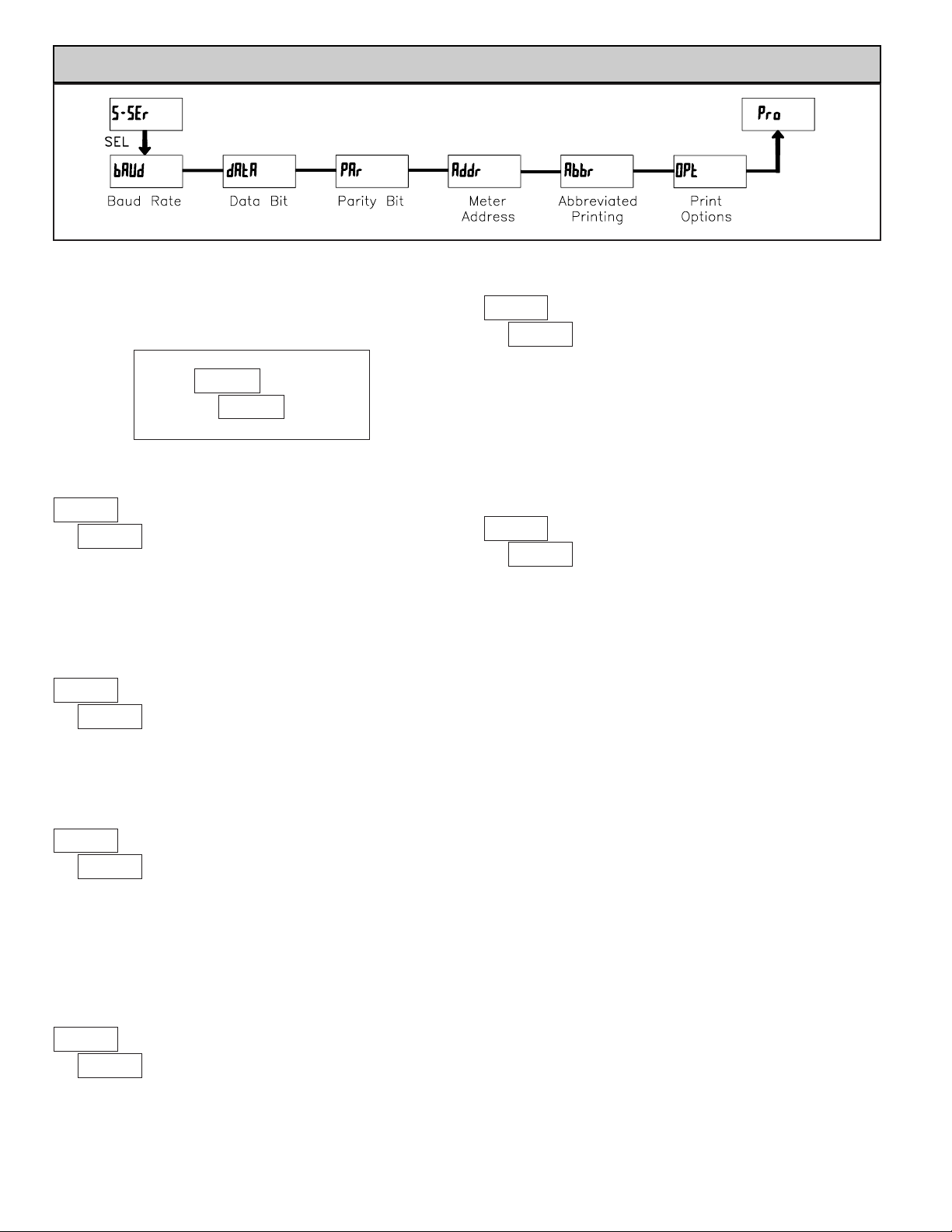
MODULE 5 - SERIAL COMMUNICATIONS PARAMETERS (5-SEr)
PARAMETER MENU
BAUD RATE
Set the baud rate to match that of other serial communications equipment.
Normally, the baud rate is set to the highest value that all of the serial
communications equipment is capable of transmitting and receiving.
Select either 7- or 8-bit data word length. Set the word length to match the
other serial communications equipment on the serial link.
This parameter only appears when the Data Bit parameter is set to a 7-bit
data word length. Set the parity bit to match that of the other serial equipment
on the serial link. The meter ignores parity when receiving data and sets the
parity bit for outgoing data. If parity is set to NO, an additional stop bit is used
to force the frame size to 10 bits.
Enter the serial node address. With a single unit, an address is not needed
and a value of zero can be used (RS232 applications). Otherwise, with multiple
bussed units, a unique address number must be assigned to each meter. The
node address applies specifically to RS485 applications.
This parameter determines the formatting of data transmitted from the meter
in response to a Transmit Value command or a Block Print Request. Select
NO
for a full print transmission, consisting of the meter address, mnemonics, and
parameter data. Select YES for abbreviated print transmissions, consisting of the
parameter data only. This setting is applied to all the parameters selected in the
PRINT OPTIONS. (Note: If the meter address is 0, the address will not be sent
during a full transmission.)
This parameter selects the meter values transmitted in response to a Print
Request. A print request is also referred to as a block print because more than
one parameter can be sent to a printer or computer as a block.
Selecting
YES displays a sublist for choosing the meter parameters to appear
in the print block. All active parameters entered as YES in the sublist will be
transmitted during a block print. Parameters entered as NO will not be sent.
The “Print All” (P-ALL) option selects all meter values for transmitting (YES),
without having to individually select each parameter in the sublist.
Note: Inactive parameters will not be sent regardless of the print option
setting. For example, the Setpoint value(s) will not be sent unless an optional
setpoint card is installed in the meter.
ª
«
9600
bAUd
ª
«
7-bit
dAtA
ª
«
Odd
PAr
ª
«
00
Addr
ª
«
NO
Abbr
ª
«
NO
OPt
0 to 99
Indicates Program Mode Alternating Display.
Factory Settings are shown.
ª
«
C"6E
Parameter
Selection/Value
ANALOG MODELS - CUB5V, CUB5I, CUB5P, CUB5TC, CUB5RT
SP2
NO
Setpoint 2
SPt-2
SP1
NO
Setpoint 1
SPt-1
MIN
NO
Minimum
LO
MAX
NO
Maximum
HI
INP
YES
Input
INP
MNEMONIC
FACTORY
SETTING
DESCRIPTIONDISPLAY
Page 3

3
Sending Serial Commands and Data
When sending commands to the meter, a string containing at least one
command character must be constructed. A command string consists of a
command character, a value identifier, numerical data (if writing data to the
meter) followed by a command terminator character, * or $.
Command Chart
Command String Construction
The command string must be constructed in a specific sequence. The meter
does not respond with an error message to illegal commands. The following
procedure details construction of a command string:
1. The first 2 or 3 characters consist of the Node Address Specifier (N) followed
by a 1 or 2 character node address number. The node address number of the
meter is programmable. If the node address is 0, this command and the node
address itself may be omitted. This is the only command that may be used in
conjunction with other commands.
2. After the optional address specifier, the next character is the command
character.
3. The next character is the register ID. This identifies the register that the
command affects. The P command does not require a register ID character. It
prints all the active selections chosen in the Print Options menu parameter.
4. If constructing a value change command (writing data), the numeric data is
sent next.
5. All command strings must be terminated with the string termination
characters * or $. The meter does not begin processing the command string
until this character is received. See Command Response Time section for
differences in meter response time when using the * and $ terminator.
Register Identification Chart
Analog Models - CUB5V, CUB5I, CUB5P, CUB5TC, CUB5RT
Command String Examples:
1. Node address = 17, Write 350 to the setpoint 1 value
String: N17VD350*
2. Node address = 5, Read input, response time of 50 msec min
String: N5TA*
3. Node address = 0, Reset Setpoint 1 output
String: RD*
4. Node address = 31, Request a Block Print Output, response time of 2 msec min
String: N31P$
Transmitting Data to the Meter
Numeric data sent to the meter must be limited to transmit details listed in the
Register Identification Chart. Leading zeros are ignored. Negative numbers
must have a minus sign. The meter ignores any decimal point and conforms the
number to the scaled resolution. (For example: The meter’s scaled decimal point
position is set for 0.0 and 25 is written to a register. The value of the register is
now 2.5. In this case, write a value of 250 to equal 25.0).
Note: Since the meter does not issue a reply to value change commands, follow
with a transmit value command for readback verification.
Initiates a block print output. Registers in the
print block are selected in Print Options.
Block Print Request
(read)
P
Reset a register value or setpoint output.
Must be followed by a register ID character
ResetR
Write to register of the meter. Must be
followed by a register ID character and
numeric data.
Value Change (write)V
Read a register from the meter. Must be
followed by a register ID character.
Transmit Value (read)T
Address a specific meter. Must be followed by
one or two digit node address. Not required
when node address = 0.
Node (meter)
Address Specifier
N
NotesDescriptionCommand
T, R, V,
T, R, V
T, R
T, R
T
Transmit Details (T and V)
5 digit positive/4 digit negativeSP2E
SP1D
5 digitMINMinimumC
5 digitMAXMaximumB
5 digitINPInputA
Applicable
Commands
MNEMONICValue DescriptionID
5 digit positive/4 digit negative
Setpoint 1
(Reset output 1)
Setpoint 2
(Reset output 2)
Receiving Data From The Meter
Data is transmitted from the meter in response to either a transmit command
(T), a block print request command (P) or a User Input print request. The
response from the meter is either a full field transmission or an abbreviated
transmission, depending on the selection chosen in Module 5.
Full Field Transmission
* These characters only appear in the last line of a block print.
The first two characters transmitted are the meter address. If the address
assigned is 0, two spaces are substituted. Aspace follows the meter address field.
The next three characters are the register mnemonic, as shown in the Register
Identification Chart.
The numeric data is transmitted next. The numeric field (bytes 7 to 15) is 9
characters long. When a requested display value exceeds the meter’s display
limits, decimal points are sent in place of numerical data to indicate a display
overrange.
The remaining 7 positions of this field consist of a minus sign (for negative
values), a floating decimal point (if applicable), and five positions for the
requested value. The data within bytes 9 to 15 is right-aligned with leading
spaces for any unfilled positions.
The end of the response string is terminated with a <CR> and <LF>. After the
last line of a block print, an extra <SP>, <CR> and <LF> are added to provide
separation between the print blocks.
Abbreviated Transmission
* These characters only appear in the last line of a block print.
The abbreviated response suppresses the node address and the register
mnemonic, leaving only the numeric part of the response.
Meter Response Examples (Analog models):
1. Node address = 17, full field response, Input = 875
17 INP 875 <CR><LF>
2. Node address = 0, full field response, Setpoint 1 = -250.5
SP1 -250.5<CR><LF>
3. Node address = 0, abbreviated response, Setpoint 2 = 250, last line of block
print 250<CR><LF><SP><CR><LF>
Byte Description
1, 2 2 byte Node Address field [00-99]
3 <SP> (Space)
4-6 3 byte Register Mnemonic field
7-15
16 <CR> (carriage return)
17 <LF> (line feed)
18 <SP>* (Space)
19 <CR>* (carriage return)
20 <LF>* (line feed)
9 byte data field; 7 bytes for number, one byte for sign, one byte for
decimal point
Byte Description
1-9
9 byte data field, 7 bytes for number, one byte for sign, one
byte for decimal point
10 <CR> (carriage return)
11 <LF> (line feed)
12 <SP>* (Space)
13 <CR>* (carriage return)
14 <LF>* (line feed)
Page 4

Command Response Time
The meter can only receive data or transmit data at any one time (half-duplex
operation). During RS232 transmissions, the meter ignores commands while
transmitting data, but instead uses RXD as a busy signal. When sending
commands and data to the meter, a delay must be imposed before sending
another command. This allows enough time for the meter to process the
command and prepare for the next command.
At the start of the time interval t1, the computer program prints or writes the
string to the com port, thus initiating a transmission. During t1, the command
characters are under transmission and at the end of this period, the command
terminating character (* or $) is received by the meter. The time duration of t
1
is dependent on the number of characters and baud rate of the channel.
t
1
= (10 times the # of characters) / baud rate
At the start of time interval t2, the meter starts the interpretation of the
command and when complete, performs the command function. This time
interval t2varies. If no response from the meter is expected, the meter is ready
to accept another command.
If the meter is to reply with data, the time interval t2is controlled by the use
of the command terminating character. The ‘*’ terminating character results in
a response time of 50 msec. minimum. This allows sufficient time for the
release of the sending driver on the RS485 bus. Terminating the command line
with ‘$’ results in a response time (t2) of 2 msec. minimum. The faster response
time of this terminating character requires that sending drivers release within 2
msec. after the terminating character is received.
At the beginning of time interval t3, the meter responds with the first
character of the reply. As with t1, the time duration of t3is dependent on the
number of characters and baud rate of the channel. At the end of t3, the meter is
ready to receive the next command.
t3= (10 times the # of characters) / baud rate
The maximum serial throughput of the meter is limited to the sum of the
times t1, t2and t3.
Timing Diagram Figure
Communication Format
Data is transferred from the meter through a serial communication channel.
In serial communications, the voltage is switched between a high and low level
at a predetermined rate (baud rate) using ASCII encoding. The receiving device
reads the voltage levels at the same intervals and then translates the switched
levels back to a character. The voltage level conventions depend on the interface
standard. The table lists the voltage levels for each standard.
Data is transmitted one byte at a time with a variable idle period between
characters (0 to ∞). Each ASCII character is “framed” with a beginning start bit,
an optional parity bit and one or more ending stop bits. The data format and
baud rate must match that of other equipment in order for communication to
take place. The figures list the data formats employed by the meter.
Start Bit and Data Bits
Data transmission always begins with the start bit. The start bit signals the
receiving device to prepare for reception of data. One bit period later, the least
significant bit of the ASCII encoded character is transmitted, followed by the
remaining data bits. The receiving device then reads each bit position as they are
transmitted.
Parity Bit
After the data bits, the parity bit is sent. The transmitter sets the parity bit to
a zero or a one, so that the total number of ones contained in the transmission
(including the parity bit) is either even or odd. This bit is used by the receiver
to detect errors that may occur to an odd number of bits in the transmission.
However, a single parity bit cannot detect errors that may occur to an even
number of bits. Given this limitation, the parity bit is often ignored by the
receiving device. The CUB5 meter ignores the parity bit of incoming data and
sets the parity bit to odd, even or none (mark parity) for outgoing data.
Stop Bit
The last character transmitted is the stop bit. The stop bit provides a single bit
period pause to allow the receiver to prepare to re-synchronize to the start of a
new transmission (start bit of next byte). The receiver then continuously looks
for the occurrence of the start bit. If 7 data bits and no parity is selected, then 2
stop bits are sent from the meter.
Character Frame Figure
LOGIC RS232* RS485*INTERFACE STATE
1 TXD,RXD; -3 to -15 V a-b < -200 mVmark (idle)
0 TXD,RXD; +3 to +15 V a-b > +200 mVspace (active)
* Voltage levels at the Receiver
Red Lion Controls
20 Willow Springs Circle
York PA 17406
Tel +1 (717) 767-6511
Fax +1 (717) 764-0839
Red Lion Controls AP
Unit 101, XinAn Plaza
Building 13, No.99 Tianzhou Road
ShangHai, P.R. China 200223
Tel +86 21 6113-3688
Fax +86 21 6113-3683
Red Lion Controls BV
Printerweg 10
NL - 3821 AD Amersfoort
Tel +31 (0) 334 723 225
Fax +31 (0) 334 893 793
 Loading...