

Page 1

1
105M12 and 108M12
Industrial Ethernet Switches
Installation
Guide
(Revised 2010-11-15)
Page 2
2
105M12 & 108M12 Industrial Ethernet Switches Installation Guide
(Revised 2010-11-15)
Page 3

3
Copyright, © N-TRON Corp., 2008
820 S. University Blvd., Suite 4E
Mobile, AL 36609 USA
All rights reserved. Reproduction, adaptation, or translation without prior written permission from N-TRON
Corp. is prohibited, except as allowed under copyright laws.
Ethernet is a registered trademark of Xerox Corporation. All other product names, company names, logos
or other designations mentioned herein are trademarks of their respective owners.
The information contained in this document is subject to change without notice. N-TRON Corp. makes no
warranty of any kind with regard to this material, including, but not limited to, the implied warranties of
merchantability or fitness for a particular purpose. In no event shall N-TRON Corp. be liable for any
incidental, special, indirect or consequential damages whatsoever included but not limited to lost profits
arising out of errors or omissions in this manual or the information contained herein.
(Revised 2010-11-15)
Page 4

4
SAFETY WARNINGS
ELECTRICAL SAFETY
WARNING: Disconnect the power cable before removing the end plates.
WARNING: Do not operate the unit with the end plates removed.
WARNING: Properly ground the unit before connecting anything else to the unit. Units not properly
grounded may result in a safety risk and could be hazardous and may void the warranty. See the
grounding technique section of this user manual for proper ways to ground the unit.
WARNING: Do not work on equipment or cables during periods of lightning activity.
WARNING: Do not perform any services on the unit unless qualified to do so.
WARNING: Observe proper DC Voltage polarity when installing power input cables. Reversing
voltage polarity can cause permanent damage to the unit and void the warranty.
HAZARDOUS LOCATION INSTALLATION REQUIREMENTS
1. WARNING: Explosion hazard. Do not remove or replace the device unless power has been switched off
or the area is known to be non-hazardous.
2. WARNING: Explosion hazard. Do not disconnect while the circuit is live or unless the area is known to
be non-hazardous..
3. WARNING: Explosion hazard. Substitution of components may impair suitability for Class I, Division 2.
4. WARNING: Install only in accordance with Local & National Codes of Authorities Having Jurisdiction.
5. Class I, Div 2 installations require that all devices connected to this product must be UL listed for the area in
which it is installed.
6. Limited Operating Voltage: 12-30V for Class I, Div 2 installations.
7. This equipment is suitable for use in Class I, Div 2, Groups A, B, C, and D, or non-hazardous locations
only.
(Revised 2010-11-15)
Page 5

5
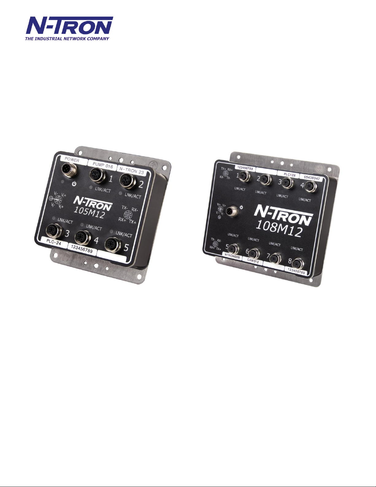
105M12 Industrial Ethernet Switch
The 105M12 is an unmanaged industrial Ethernet switch providing five Fast Ethernet copper ports in an
IP65/IP67 rated enclosure for protection against temporary immersion in water. The switch provides
Category-5 compliant 10/100BaseTX connections with IP65/67 rated M12 D-code connectors for high
performance network design, and hub/repeater upgrades. The switch is capable of auto negotiating 10/100
Mb and half/full duplex communications.
108M12 Industrial Ethernet Switch
The 108M12 is an unmanaged industrial Ethernet switch providing eight Fast Ethernet copper ports in an
IP65/IP67 rated enclosure for protection against temporary immersion in water. The switch provides eight
Category-5 compliant 10/100BaseTX connections with IP65/67 rated M12 D-code connectors for high
performance network design, and hub/repeater upgrades. The switch is capable of auto negotiating 10/100
Mb and half/full duplex communications.
Key Features
IP65 Rated for protection against low pressure jets of water from any direction
IP66 Rated for protection against high pressure jets of water from any direction
IP67 Rated for protection against temporary immersion in water
Full IEEE 802.3
Extended Environmental Specifications
Support for Full/Half Duplex Operation
Auto MDI/MDIX (crossover) on all ports
LED Link/Activity Status Indication
Autonegotiation, Autosensing Speed, Duplex, and Flow Control
Up to 1.0 Gb/s maximum throughput for the 105M12 and 1.6 Gb/s for the 108M12 model
Redundant power input
Bulk head mountable (optional Industry Standard 35mm DIN rail mounting available)
108M12-HV Only
(Revised 2010-11-15)
Page 6

6
INGRESS PROTECTION IP67
1st IP
Protection against ingress of solids
2nd IP
Protection against ingress of liquids
0
No protection
0
No protection
1
Protected against solid objects over 50mm e.g. hands,
large tools.
1
Protected against vertically falling drops of water.
2
Protected against solid objects over 12mm e.g. hands,
large tools.
2
Protected against direct sprays of water up to 15° from
vertical.
3
Protected against solid objects over 2.5mm e.g. wire,
small tools.
3
Protected against direct sprays of water up to 60° from
vertical.
4
Protected against solid objects over 1.0mm e.g. wires.
4
Protected against water sprayed from any direction.
Limited ingress permitted.
5
Limited protection against dust ingress (no harmful
deposit)
5
Protected against low pressure water jets from any
direction. Limited ingress permitted.
6
Totally protected against dust ingress.
6
Protected against high pressure water jets from any
direction. Limited ingress permitted.
7
Protected against temporary immersion between 15cm
to 1m.
8
Protected against long periods of immersion under
pressure.
The classification of degrees of protection provided by the enclosures is defined by IEC 60529. Each rating is
defined by specific tests.
The IP number is comprised of two numbers, the first referring to the protection against solid objects and the
second against fluids. The higher the number, the better the device is protected against contact with moving
parts and the harmful entry of various forms of moisture.
The 105M12 and 108M12 Industrial Ethernet Switches are fully protected against dust and will remain sealed
when immersed in water to a depth of 1 meter for 1 hour when all the ports are properly mated or sealed.
These IP67 caps seal off the unused ports protecting them from dirt, water, oil or any other
contaminants which might be present in the close proximity of the switch.
PACKAGE CONTENTS
Please make sure the Ethernet Switch package contains the following items:
1. 105M12 or 108M12 Industrial Ethernet Switch
2. Product CD
UNPACKING
Remove all the equipment from the packaging, and store the packaging in a safe place. File any damage
claims with the carrier.
(Revised 2010-11-15)
Page 7

7
INSTALLATION
Read the following warning before beginning the installation:
WARNING
Never install or work on electrical equipment or cabling during periods of lightning activity.
BULKHEAD MOUNTING
The following are the mechanical dimensions and drill hole placements to consider when mounting the
105M12 and 108M12 Industrial Ethernet Switches:
(Revised 2010-11-15)
Page 8

8
FRONT PANEL
LED
Color
Description
ON
Power is Applied.
OFF
Power is OFF.
LNK/ACT
ON
Link established, no Activity on cable.
BLINKING
Link established, Activity on cable
OFF
No link established
LNK/ACT Link/Activity LED
M12 D-Coded Female Ports All ports are Auto sensing 10/100BaseTX Connections
M12 A-Coded Male Port Redundant Power Input (10-30VDC)
Green LED lights when Power is connected
LED’s: The table below describes the operating modes:
(Revised 2010-11-15)
Page 9

9
APPLYING POWER
The M12 A coded power connector is keyed, where the mating connection from the power supply can
be made only when the male and female ends are lined up properly.
When the power is first connected all LED’s will flash ON Momentarily.
Verify the Power LED stays ON (GREEN).
Note: Either V1 or V2 can be connected to power for minimal operation. For redundant power
operation, V1 and V2 must be connected to separate DC Voltage sources. The power cord should be
limited to less than 10 meters in order to ensure optimum performance.
Recommended 24V DC Power Supplies, similar to:
100VAC/240VAC:
N-Tron NTPS-24-1.3, DC 24V/1.3A
(Revised 2010-11-15)
Page 10

10
N-TRON 105M12 AND 108M12 GROUNDING TECHNIQUES
Drain wire with lug connecting switch chassis to known grounding point.
CONNECTING THE UNIT
For 10Base-T ports, plug a Category 3 (or greater) twisted pair cable into the M12 connector. For
100Base-T ports, plug a Category 5 (or greater) twisted pair cable into the M12 connector. Connect the
other end to the far end station. Verify that the LNK LED’s are ON once the connection has been
completed. To connect any other port to another Switch or Repeater, use a standard Cat5 straight
through or crossover cable.
Warning: Creating a port to port connection on the same switch (i.e. loop) is an illegal operation and
will create a broadcast storm which will crash the network!
TROUBLESHOOTING
1. Make sure the (Power LED) is ON.
2. Verify that Link LED’s are ON or BLINKING for connected ports.
3. Verify cabling used between stations.
4. Verify that cabling is Category 5 (or greater) for 100Mbit Operation.
SUPPORT
Contact N-TRON Corp. at:
TEL: 251-342-2164
FAX: 251-342-6353
www.n-tron.com
N-TRON_Support@n-tron.com
(Revised 2010-11-15)
Page 11

11
FCC STATEMENT
This product complies with Part 15 of the FCC-A Rules.
Operation is subject to the following conditions:
(1) This device may not cause harmful interference
(2) This device must accept any interference received, including interference that may cause undesired
operation.
NOTE: This equipment has been tested and found to comply with the limits for a Class A digital device,
pursuant to Part 15 of the FCC Rules. These limits are designed to provide reasonable protection against
harmful interference in a residential installation. This equipment generates, uses, and can radiate radio
frequency energy and, if not installed and used in accordance with the instructions, may cause harmful
interference to radio communications. Operation of this device in a residential area is likely to cause
harmful interference in which case the user will be required to correct the interference at his own expense.
INDUSTRY CANADA
This Class A digital apparatus meets all requirements of the Canadian Interference Causing Equipment
Regulations. Operation is subject to the following two conditions; (1) this device digital apparatus meets all
requirements of the Canadian Interference Causing Equipment Regulations. Operation is subject to the
following two conditions; (1) this device may not cause harmful interference, and (2) this device must
accept any interference received, including interference that may cause undesired operation.
Cet appareillage numérique de la classe A répond à toutes les exigences de l'interférence canadienne causant
des règlements d'équipement. L'opération est sujette aux deux conditions suivantes: (1) ce dispositif peut ne
pas causer l'interférence nocive, et (2) ce dispositif doit accepter n'importe quelle interférence reçue, y
compris l'interférence qui peut causer l'opération peu désirée.
(Revised 2010-11-15)
Page 12

12
KEY SPECIFICATIONS – 105M12
Screw On Field Terminated Right
Angle Connector
Front: 3" (7.62 cm)
Screw On Field Terminated
Straight Version Connector
Front: 4" (10.16 cm)
Physical
Height: 5.00” (12.7cm)
Width: 4.32” (10.97cm)
Depth: 1.8” (4.57cm)
Weight: 1.8 lbs. (0.81kg)
DIN Rail: 35 mm (Optional)
Electrical
Input Voltage: 10-30 VDC (Regulated)
Input Current: 215 mA max. @ 24VDC (Steady State)
Inrush Current: 7.8 Amp/0.7ms max. @ 24VDC
Input Ripple: Less than 100 mV
Environmental
Operating Temperature: -40°C to 80°C
Storage Temperature: -40°C to 85°C
Operating Humidity: 5-100% (Non Condensing)
Operating Altitude: 0 to 10,000 ft.
Network Media
10BaseT: > Cat-3 Cable
100BaseT: > Cat-5 Cable
Connectors
10/100BaseTX: M12, 4 Pin, D-code
Power: M12, 5 Pin, A-code
Pin Assignments
Recommended Wiring Clearance:
(Revised 2010-11-15)
Page 13

13
KEY SPECIFICATIONS – 108M12
Screw On Field Terminated Right
Angle Connector
Front: 3" (7.62 cm)
Screw On Field Terminated
Straight Version Connector
Front: 4" (10.16 cm)
Physical
Height: 6.62” (16.81cm)
Width: 6.62” (16.81cm)
Depth: 1.8” (4.57cm)
Weight: 3.3 lbs. (1.49kg)
DIN Rail 35 mm (Optional)
Electrical
Input Voltage: 10-30 VDC (Regulated)
-HV Option: 10-60 VDC (Regulated)
Input Current: 250 mA max. @ 24VDC (Steady State)
Inrush Current: 8.1 Amp/0.7ms max. @ 24VDC
Input Ripple: Less than 100 mV
Environmental
Operating Temperature: -40°C to 70°C
Storage Temperature: -40°C to 85°C
Operating Humidity: 5-100% (Non Condensing)
Operating Altitude: 0 to 10,000 ft.
Network Media
10BaseT: > Cat-3 Cable
100BaseT: > Cat-5 Cable
Connectors
10/100BaseTX: M12, 4 Pin, D-code
Power: M12, 5 Pin, A-Code
Pin Assignments
Recommended Wiring Clearance:
(Revised 2010-11-15)
Page 14

14
Regulatory Approvals:
Safety: Suitable for use in Class I, Division 2, Groups A, B, C and D Hazardous Locations, or Nonhazardous
Locations only.
The high voltage model is TÜV approved GS per EN 60950-1.
EMI: EN61000-6-4, EN55011 - Class A
FCC Title 47, Part 15, Subpart B - Class A
ICES-003 – Class A
EMS: EN61000-6-2
EN61000-4-2 (ESD)
EN61000-4-3 (RS)
EN61000-4-4 (EFT)
EN61000-4-5 (Surge)
EN61000-4-6 (Conducted Disturbances)
GOST-R Certified.
Warranty: Effective January 1, 2008, all N-TRON products carry a 3 year limited warranty from the date of
purchase.
(Revised 2010-11-15)
Page 15

15
N-TRON Limited Warranty
N-TRON, Corp. warrants to the end user that this hardware product will be free from defects in workmanship and materials,
under normal use and service, for the applicable warranty period from the date of purchase from N-TRON or its authorized
reseller. If a product does not operate as warranted during the applicable warranty period, N-TRON shall, at its option and
expense, repair the defective product or part, deliver to customer an equivalent product or part to replace the defective item, or
refund to customer the purchase price paid for the defective product. All products that are replaced will become the property of
N-TRON. Replacement products may be new or reconditioned. Any replaced or repaired product or part has a ninety (90) day
warranty or the remainder of the initial warranty period, whichever is longer.
N-TRON shall not be responsible for any custom software or firmware, configuration information, or memory data of customer
contained in, stored on, or integrated with any products returned to N-TRON pursuant to any warranty.
OBTAINING WARRANTY SERVICE: Customer must contact N-TRON within the applicable warranty period to obtain
warranty service authorization. Dated proof of purchase from N-TRON or its authorized reseller may be required. Products
returned to N-TRON must be pre-authorized by N-TRON with a Return Material Authorization (RMA) number marked on the
outside of the package, and sent prepaid and packaged appropriately for safe shipment. Responsibility for loss or damage does not
transfer to N-TRON until the returned item is received by N-TRON. The repaired or replaced item will be shipped to the
customer, at N-TRON’s expense, not later than thirty (30) days after N-TRON receives the product.
N-TRON shall not be responsible for any software, firmware, information, or memory data of customer contained in, stored on, or
integrated with any products returned to N-TRON for repair, whether under warranty or not.
ADVANCE REPLACEMENT OPTION: Upon registration, this product qualifies for advance replacement. A replacement
product will be shipped within three (3) days after verification by N-TRON that the product is considered defective. The
shipment of advance replacement products is subject to local legal requirements and may not be available in all locations. When
an advance replacement is provided and customer fails to return the original product to N-TRON within fifteen (15) days after
shipment of the replacement, N-TRON will charge customer for the replacement product, at list price.
WARRANTIES EXCLUSIVE: IF AN N-TRON PRODUCT DOES NOT OPERATE AS WARRANTED ABOVE,
CUSTOMER'S SOLE REMEDY FOR BREACH OF THAT WARRANTY SHALL BE REPAIR, REPLACEMENT, OR
REFUND OF THE PURCHASE PRICE PAID, AT N-TRON'S OPTION. TO THE FULL EXTENT ALLOWED BY LAW, THE
FOREGOING WARRANTIES AND REMEDIES ARE EXCLUSIVE AND ARE IN LIEU OF ALL OTHER WARRANTIES,
TERMS, OR CONDITIONS, EXPRESS OR IMPLIED, EITHER IN FACT OR BY OPERATION OF LAW, STATUTORY OR
OTHERWISE, INCLUDING WARRANTIES, TERMS, OR CONDITIONS OF MERCHANTABILITY, FITNESS FOR A
PARTICULAR PURPOSE, SATISFACTORY QUALITY, CORRESPONDENCE WITH DESCRIPTION, AND NONINFRINGEMENT, ALL OF WHICH ARE EXPRESSLY DISCLAIMED. N-TRON NEITHER ASSUMES NOR AUTHORIZES
ANY OTHER PERSON TO ASSUME FOR IT ANY OTHER LIABILITY IN CONNECTION WITH THE SALE,
INSTALLATION, MAINTENANCE OR USE OF ITS PRODUCTS. N-TRON SHALL NOT BE LIABLE UNDER THIS
WARRANTY IF ITS TESTING AND EXAMINATION DISCLOSE THAT THE ALLEGED DEFECT OR MALFUNCTION
IN THE PRODUCT DOES NOT EXIST OR WAS CAUSED BY CUSTOMER'S OR ANY THIRD PERSON'S MISUSE,
NEGLECT, IMPROPER INSTALLATION OR TESTING, UNAUTHORIZED ATTEMPTS TO OPEN, REPAIR OR MODIFY
THE PRODUCT, OR ANY OTHER CAUSE BEYOND THE RANGE OF THE INTENDED USE, OR BY ACCIDENT, FIRE,
LIGHTNING, POWER CUTS OR OUTAGES, OTHER HAZARDS, OR ACTS OF GOD.
LIMITATION OF LIABILITY: TO THE FULL EXTENT ALLOWED BY LAW, N-TRON ALSO EXCLUDES FOR ITSELF
AND ITS SUPPLIERS ANY LIABILITY, WHETHER BASED IN CONTRACT OR TORT (INCLUDING NEGLIGENCE),
FOR INCIDENTAL, CONSEQUENTIAL, INDIRECT, SPECIAL, OR PUNITIVE DAMAGES OF ANY KIND, OR FOR
LOSS OF REVENUE OR PROFITS, LOSS OF BUSINESS, LOSS OF INFORMATION OR DATA, OR OTHER FINANCIAL
LOSS ARISING OUT OF OR IN CONNECTION WITH THE SALE, INSTALLATION, MAINTENANCE, USE,
PERFORMANCE, FAILURE, OR INTERRUPTION OF ITS PRODUCTS, EVEN IF N-TRON OR ITS AUTHORIZED
RESELLER HAS BEEN ADVISED OF THE POSSIBILITY OF SUCH DAMAGES, AND LIMITS ITS LIABILITY TO
REPAIR, REPLACEMENT, OR REFUND OF THE PURCHASE PRICE PAID, AT N-TRON'S OPTION. THIS DISCLAIMER
OF LIABILITY FOR DAMAGES WILL NOT BE AFFECTED IF ANY REMEDY PROVIDED HEREIN SHALL FAIL OF
ITS ESSENTIAL PURPOSE.
DISCLAIMER: Some countries, states, or provinces do not allow the exclusion or limitation of implied warranties or the
limitation of incidental or consequential damages for certain products supplied to consumers, or the limitation of liability for
personal injury, so the above limitations and exclusions may be limited in their application to you. When the implied warranties
are not allowed to be excluded in their entirety, they will be limited to the duration of the applicable written warranty. This
warranty gives you specific legal rights which may vary depending on local law.
GOVERNING LAW: This Limited Warranty shall be governed by the laws of the State of Delaware, U.S.A.
(Revised 2010-11-15)
 Loading...