

Page 1
Thank you for purchasing our IP camera.
This Quick Reference guide describes how to install
and configure your RedLeaf IP camera.
Before you start to install and use your new camera,
please read these instructions carefully.
Please keep this start guide well for future reference.
Please open the accessory bag to check the items one
by one in accordance with the list below. Contact your
local retailer ASAP if something is missing or damaged
in the bag.
For the most up-to-date information about this product,
visit the official RedLeaf website at
www.redleafsecurity.net
Before your operation please read the following
instructions carefully.
1.Electrical safety
All installation and operation here should conform to
your local electrical safety codes.
The power shall conform to the requirement in the SELV
(Safety Extra Low Voltage) and the Limited power
source is rated 12V DC in the IEC60950-1.
Please note: Do not connect these two power
supplying sources to the device at the same time; it
may result in device damage!
We assume no liability or responsibility for all the fires or
electr ical shock caused by imprope r handling or
installation.
We a re n ot liab le for any prob lems ca used by
unauthorized modification or attempted repair.
2.Transportation security
Heavy stress, violent vibration or water splash are not
allowed during transportation, storage and installation.
3.Installation
Do not apply power to the camera before completing
installation.
Please install the proper power cut-off device during the
installation connection.
Always follow the instruction guide the manufacturer
recommended.
4.Qualified engineers needed
All the examination and repair work should be done by
the qualified service engineers.
We a re n ot liab le f or any prob lems ca used by
unauthorized modifications or attempted repair.
5.Environment
This series IP camera should be installed in a cool, dry
place away from direct sunlight, inflammable, explosive
substances and etc.
Please keep it away from the electromagnetic radiation
object and environment.
Please make sure the CCD (CMOS) component is out
of the radiation of the laser beam device. Otherwise it
may result in CCD (CMOS) optical component damage.
Please keep the sound ventilation.
Do not allow the water and other liquid falling into the
camera.
Thunder-proof device is recommended to be adopted to
better prevent thunder.
The grounding studs of the product are recommended
to be grounded to further enhance the reliability of the
camera.
6. Daily Maintenance
Please shut down the device and then unplug the power
cable before you begin daily maintenance work.
Do not touch the CCD (CMOS) optic component. You
can use the blower to clean the dust on the lens surface.
Always use the dry soft cloth to clean the device. If
there is too much dust, please use the water to dilute the
mild detergent first and then use it to clean the device.
Finally use the dry cloth to clean the device.
Please put the dust proof cap to protect the CCD
(CMOS) component when you do not use the camera.
7. Accessories
Be sure to use all the accessories recommended by
manufacturer.
Before installation, please open the package and check
all the components are included.
Contact your local retailer ASAP if something is broken
in your package.
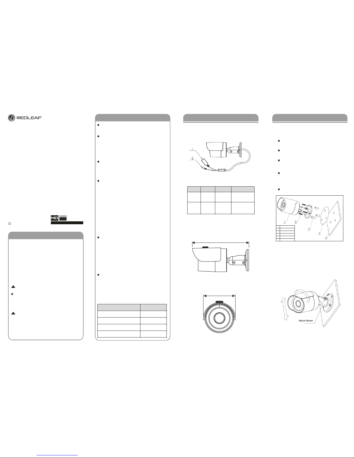
1.1 Multiple-function Combination Cable
You can refer to the following figure for multiple-function
combination cable information.
See -Figure 1-1.
Please refer to the following sheet for detailed information.
1.2 Framework and Dimension
Please refer to the fol lowing figure for dimensio n
information. The unit is mm.
See -Figure 1-2 and -Figure 1-3.
Please follow the steps listed below to install the device.
Please refer to - Figure 2-1 and Figure 2-2 for
reference.
Paste the installation map on the surface of the
wall or the ceiling.
Dig the installation holes according to the
installation map.
Open the accessories bag and then take the
expansion bolt out. Insert the expansion bolt
into the installation holes.
Take the screws from the accessories bag and
then use them to secure the device on the
installation surface of the wall or the ceiling.
Connect the corresponding cables.
Use the cross-head screwdriver to loosen the
adjust screw.
Turn the device in different directions to make
it suitable for the monitor position.
Use the cross-head screwdriver to fix the
adjust screw firmly. See Figure 2-2.
Welcome
Welcome Framework
Device Installation
Port Name Function Connection Note
Connect to standard
Ethernet cable.
Powe r input por t.
Inpu t DC 12V
Ethernet PortNetwork Port
Power input
port
1. LAN
2. DC 12V
/
Name
IPC Unit
Installation Screw
Expansion Bolt
Installation Map
Ceiling or Wall
No.
1.
2.
3.
4.
5.
Accessory Name Amount
RLC Unit 1
Accessories Bag 1
Quick Start Guide 1
CD 1 Resource
1080
FULL HD
www.Redleafsecurity.net
c 2012 Redleaf Corporation
Mini Bullet Series
Version 1.1.0
Installation Manual
Before operating the unit
please read this manual
thoroughly and retain it for
future reference.
Network Camera
Figure 1-1
Figure 1-2
Figure 1-3
Figure 2-1
Figure 2-2
!
!
165
70
Page 2
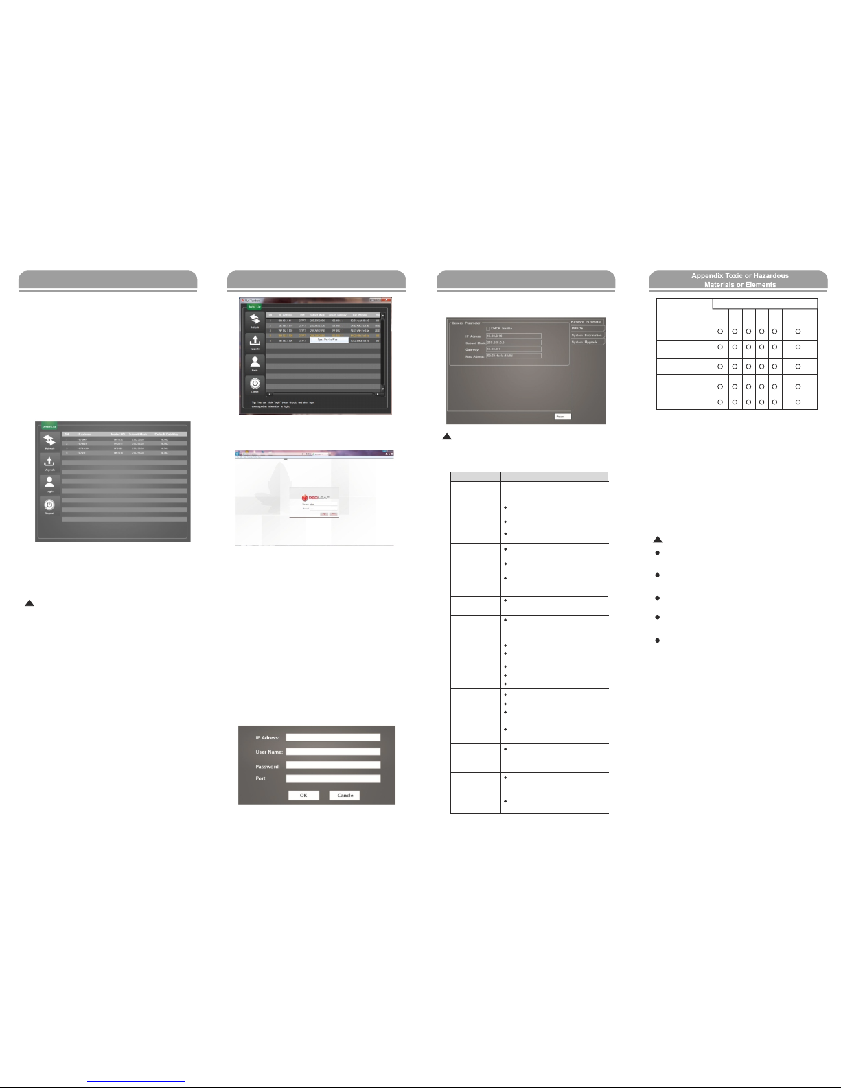
Select the “Open Device Web” item; you can go to the
corresponding web login interface. See -Figure 3-3.
If you want to modify the device IP address without
logging in the device web interface, you can go to the
configuration tool main interface to set.
In the configuration tool search interface (Figure 3-4),
please select a device IP address and then double click
it to open the login interface. Or you can select an IP
address and then click the Login button to go to the login
interface. See -Figure 3-4.
In -Figure 3-4, you can view device IP address, user
na me, pas sw or d a nd po rt. P leas e mod ify t he
corresponding information to login.
Please note the port information here shall be identical
with the port value you set in TCP port in Web Network
interface. Otherwise, you can not login the device.
If you are using device background upgrade port 3800
to login, other setups are all invalid.
3.1 Overview
Quick configuration tool can search current IP
address, modify IP address. At the same time, you
can use it to upgrade the device.
Plea se n ote the to ol o nly app lies to the IP
addresses in the same segment.
3.2 Operation
Double click the “ConfigTools.exe” icon; you can
see an interface is shown as in -Figure 3-1.
In the device list interface, you can view device IP
addr ess , po rt n umb er, su bne t ma sk, def aul t
gateway, MAC address and etc.
Select one IP address and then right click mouse,
you can see an interface is shown as in -Figure 3-2.
Note:
You can set the IP address, subnet mask and
gateway for the RLC and PC. Please note RLC IP
address and PC IP address shall be in the same
network segment if there is no router. RLC default
IP address is 192.168.1.108. If there is a router,
please set the corresponding gateway and subnet
mask.
The fa ctory defaul t user name is ad min an d
password is admin. For security reasons, please
modify your password after you first login.
For detailed WEB operation, please refer to the
RLC Web Operation Manual in the resource CD.
After you logged in, the configuration tool main interface
is shown as below. See -Figure 3-5
For de tai led in forma tio n and ope rat ion
instruction of the quick configuration tool, please
refer to the Quick Configuration Tool User's Manual
included in the resources CD.
O: Indicates that the concentration of the hazardous substance in
all homogeneous materials in the parts is below the relevant
threshold of the SJ/T11363-2006 standard.
X: Indicates that the concentration of the hazardous substance of
at least one of all homogeneous materials in the parts is above
the relevant threshold of the SJ/T11363-2006 standard. During
the environmental-friendly use period (EFUP) period, the toxic or
hazardous substance or elements contained in products will not
leak or mutate so that the use of these (substances or elements)
will not result in any severe environmental pollution, any bodily
injury or damage to any assets. The consumer is not authorized
to process such kind of substances or elements, please return to
the corresponding local authorities to process according to your
local government statutes.
Note:
Th is quick start guide is for reference only. Slight
difference may be found in user interface.
All the designs and software here are subject to change
without prior written notice.
All trademarks and registered trademarks mentioned are
the properties of their respective owners.
If there is any uncertainty or controversy, please refer to
the final explanation of us.
Please visit our website or contact your local service
engineer for more information.
Quick Configuration Tool Quick Configuration Tool Quick Configuration Tool
· There is no player.
·
There is no DX8.1 or higher.
·
For the MEDIA PLAYER, there shall be
Div X503Bundle.exe plugin if you play
the .AVI file.
For Windows XP user, you need to
install the plugin DivX503Bundle.exe
and ffdsho-2004 1012.exe.
After you modified the important setup,
please reboot the device via the
software to make sure the setup has
been updated to the storage medium.
To guarantee
setup update
I can not play the
download file.
Power adapter
· The general power adapter can work
ranging from 0℃ to 40 ℃. The device
may result in unstable power supply
when the temperature exceeds the
working temperature.
Please replace an industry-level power
adapter if you are using in the harsh
environments.
I can not boot up
the device or
operate properly.
The water leakage
occurred.
Please click RESET button for at least
five seconds to restore factory default setup.
The glass front cap has sustained
heavy push or strike.
The waterproof plug of the rear cap
becomes loosen.
The unauthorized front or rear cap
remove many result in water leakage.
IR video is poor.
· Do not use the proper supplying power.
The IR light can not turn on completely.
The object is out of the IR distance
range of current device.
IR-CUT does not turn to the night mode.
The photosensitive chip of the front-end
can not sense the IR light.
I can not upgrade
the device via
network.
When network upgrade operation failed,
you can use port 3800 to continue
upgrade.
I can not login the
client-end or the
WEB
· For Windows OS 98 or Windows ME
user, if you can not install the client-end
or can not view after the installation.
We recommend the win2000sp4 OS or
install the client-end of the low version.
· The Active X control is blocked.
· The display card version shall be dx8.
1 or higher.
· Network connection error occurred.
· Invalid network setup.
Invalid user name or password.
Bug
Component
Name
Circuit Board
Component
Device Case
Wire and Cable
Packing
Components
Accessories
Pb Hg Cd Cr VIP BBPBDE
Toxic or Hazardous Materials or Elements
Figure 3-1
Figure 3-3
Figure 3-4
Figure 3-2
Figure 3-5
!
!
!
 Loading...