

Page 1

1
Page 2

2
WELCOME
Thank you for purchasing our IP camera! This user’s
manual is designed to be a reference tool for your system.
Please read the following safeguards and warnings
carefully before you use this series product!
Please keep this user’s manual well for future reference!
Page 3

3
IMPORTANT SAFEGUARDS AND WARNINGS
1. ELECTRICAL SAFETY
All installation and operation here should conform to your local electrical safety codes.
The power shall conform to the requirement in the SELV (Safety Extra
Low Voltage) and the Limited power source is rated 12V DC in the IEC1-60950. We assume no
liability or responsibility for all the fires or electrical shock caused by improper handling or
installation.
We are not liable for any problems caused by unauthorized modification or attempted repair.
2. TRANSPORTATION SECURITY
Heavy stress, violent vibration or water splash are not allowed during transportation, storage
and installation.
3. INSTALLATION
Do not apply power to the camera before completing installation.
Please install the proper power cut-off device during the installation connection. Always follow
the instruction guide the manufacturer recommended.
4. QUALIFIED ENGINEERS NEEDED
All the examination and repair work should be done by the qualified service engineers.
We are not liable for any problems caused by unauthorized modifications or attempted repair
5. ENVIROMENT
This series IP camera should be installed in a cool, dry place away from direct sunlight,
inflammable, explosive substances and etc. Please keep it away from the electromagnetic
radiation object and environment.
Please make sure the CCD (CMOS) component is out of the radiation of the laser beam device.
Otherwise it may result in CCD (CMOS) optical component damage.
Please keep the sound ventilation.
Do not allow the water and other liquid falling into the camera. Thunder-proof device is
recommended to be adapted to better prevent thunder.
The grounding holes of the product are recommended to be grounded to further enhance the
reliability of the camera.
6. DAILY MAINTENANCE
Please shut down the device and then unplug the power cable before you begin daily
maintenance work.
Do not touch the CCD (CMOS) optic component. You can use the blower to clean the dust on
the lens surface.
Page 4

4
Always use the dry soft cloth to clean the device. If there is too much dust, please use the water
to dilute the mild detergent first and then use it to clean the device. Finally use the dry cloth to
clean the device.
Please put the dustproof cap to protect the CCD (CMOS) component when you do not use the
camera.
ACCESSORIES
1. ELEC TRICAL SAFETY
All installation and operation here should conform to your local electrical safety codes. The
power shall conform to the requirement in the SELV (Safety Extra Low Voltage) and the Limited
power source is rated 12V DC or 24V AC in the IEC1 -60950.
Before you replace the SD card, please unplug the power cable and then remove the shell. We
assume no liability or responsibility for all the fires or electrical shock caused by improper
handling or installation. We are not liable for any problems caused by unauthorized
modifications or attempted repairs.
2. INSTALLATION
Do not apply power to the IP camera before completing installation.
Do not put object on the IP camera.
3. ENVIROMENT
This series IP camera should be installed in a cool, dry place away from direct sunlight,
inflammable, explosive substances and etc.
The working temperature ranges from 10- to 60+. Please keep it away from the
electromagnetic radiation object and environment.
Please keep the sound ventilation.
Do not allow the water and other liquid falling into the RLC.
Thunder-proof device is recommended to be adopted to better prevent thunder. The grounding
studs of the product are recommended to be grounded to further enhance the reliability of the
camera.
4. DAILY MAINTENANCE
Current series RLC has no power button. Please unplug all corresponding power cables before
your installation.
Do not touch the CCD or CMOS part; you can use the blower to clean the dust on the surface of
the lens. You can use the dry cloth with some alcohol to clear if necessary.
Please keep the dustproof cap back to protect the CCD or CMOS part if the IP camera does not
work for a long time.
Page 5
5
If there is too much dust on the housing, please use the water to dilute the mild detergent first
and then use it to clean the device with the clear dry cloth. Finally use the dry cloth to clean the
device.
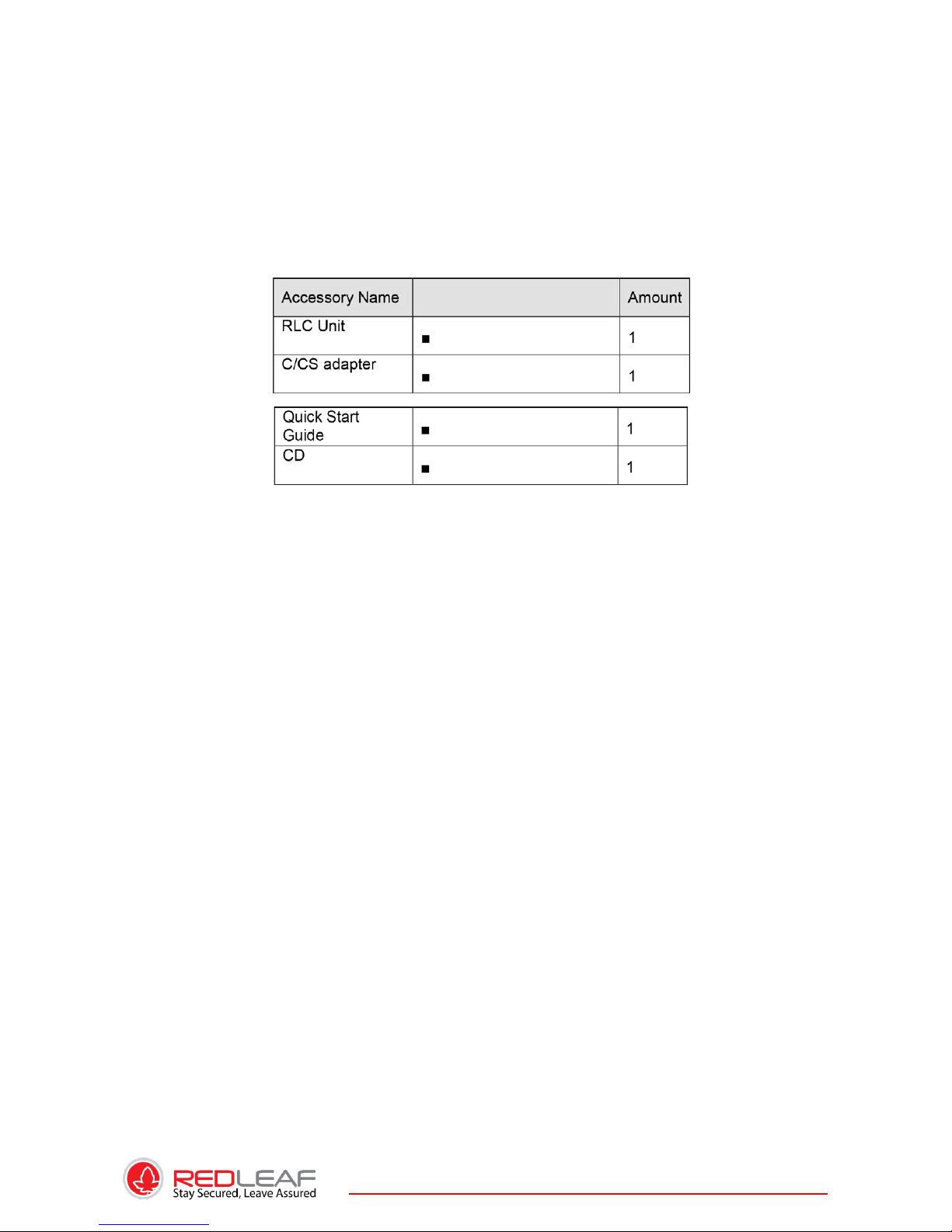
5. ACCESSORIES
Please open the accessory bag to check the items one by one in accordance with the list below.
Contact your local retailer ASAP if something is missing or damaged in the bag.
Page 6
6
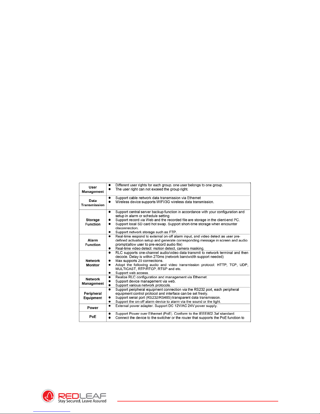
1. GENERAL INTRODUCTION
1.1. Overview
This series IP camera integrates the traditional camera and network video technology. It
adopts audio and video data collection, transmission together. It can connect to the
network directly without any auxiliary device.
This series RLC uses standard H.264 video compression technology and MJPEG audio
compression technology, which maximally guarantee the audio and video quality.
This series RLC enclosure has the strong resistance capacity, which can guarantee the
proper work performance under heavy strike. It supports real-time monitor and motion
detect function. It can be used alone or used in a network area. When it is used lonely, you
can connect it to the network and then use a network client-end. Due to its multiple
functions and various uses, this series RLC is widely used in many environments such office,
bank, road monitor and etc.
1.2. Features
Page 7
7
1.3. SPECIFICATIONS
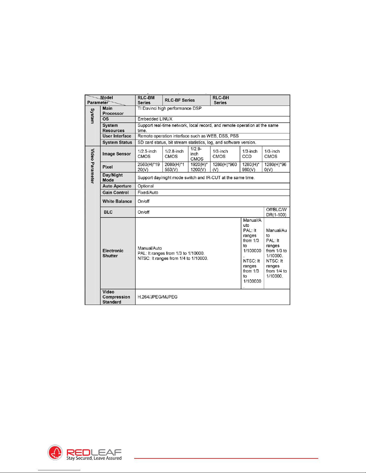
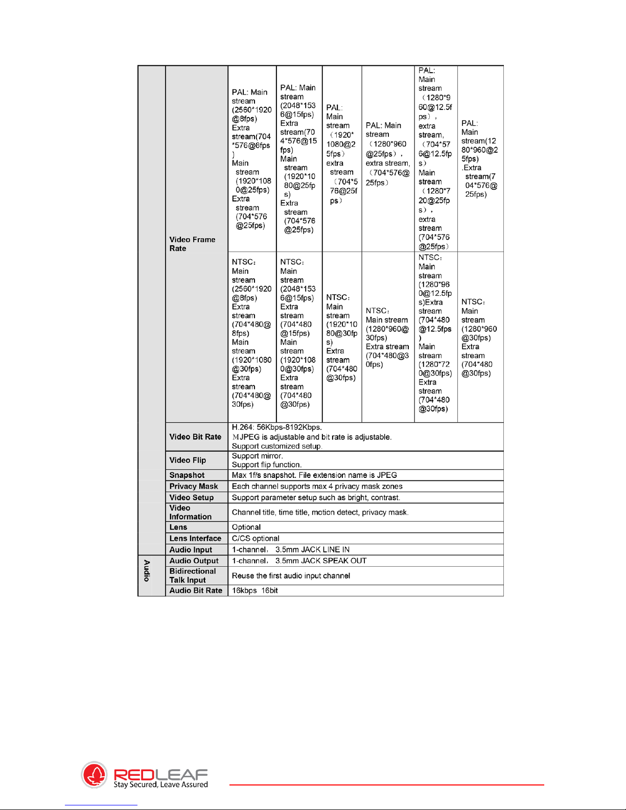
1.3.1. Performance
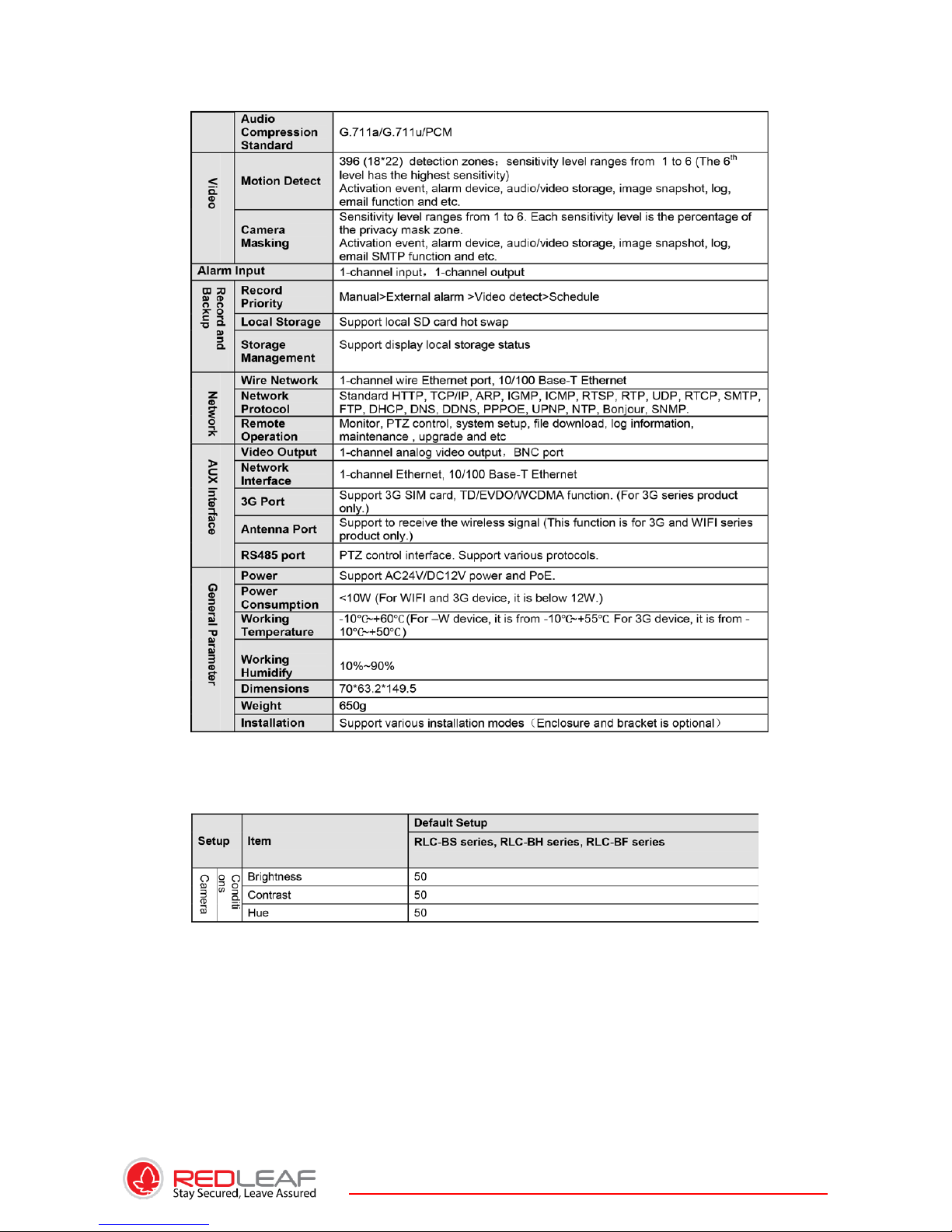
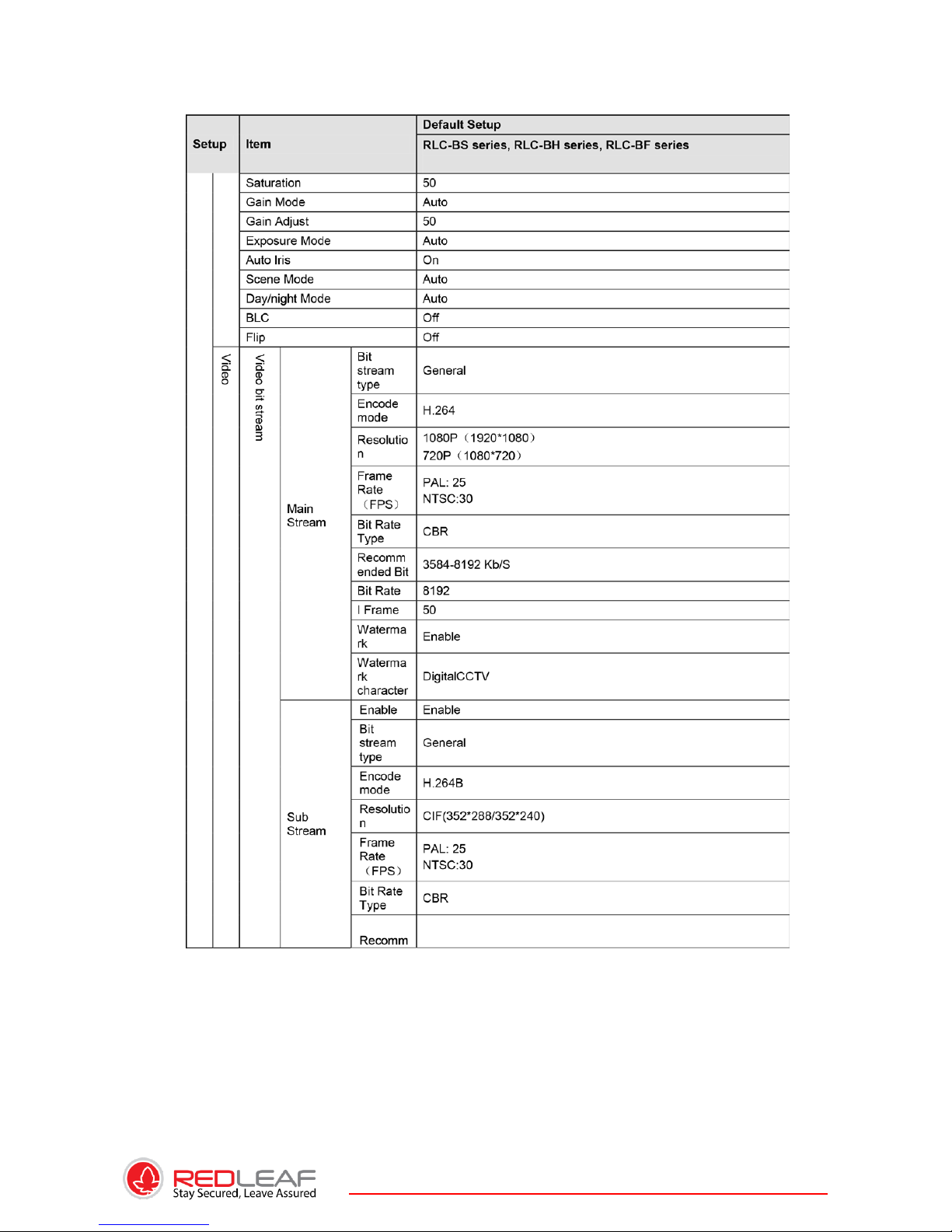
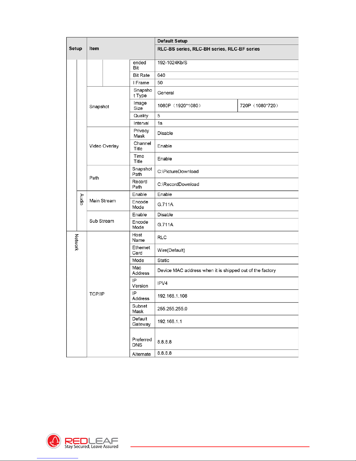
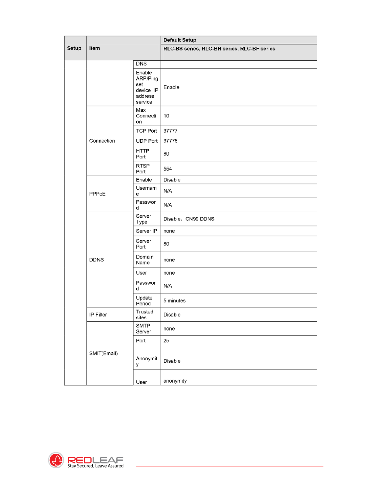
Please refer to the following sheet for RLC performance specification.
Page 8
8
Page 9
9
Page 10
10
Page 11
11
Page 12
12
Page 13
13
Page 14
14
Page 15
15
Page 16
16
Page 17
17
Page 18
18
2. FRAMEWORK
2.1. Rear Panel
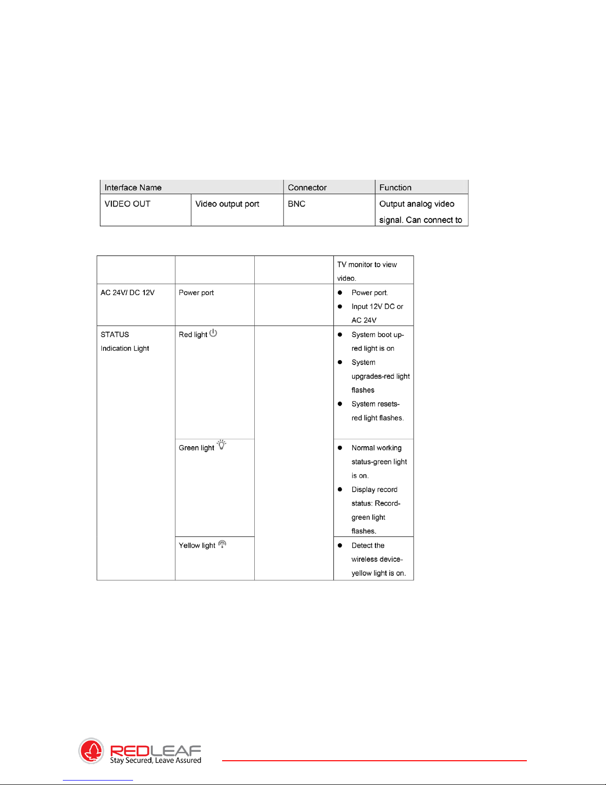
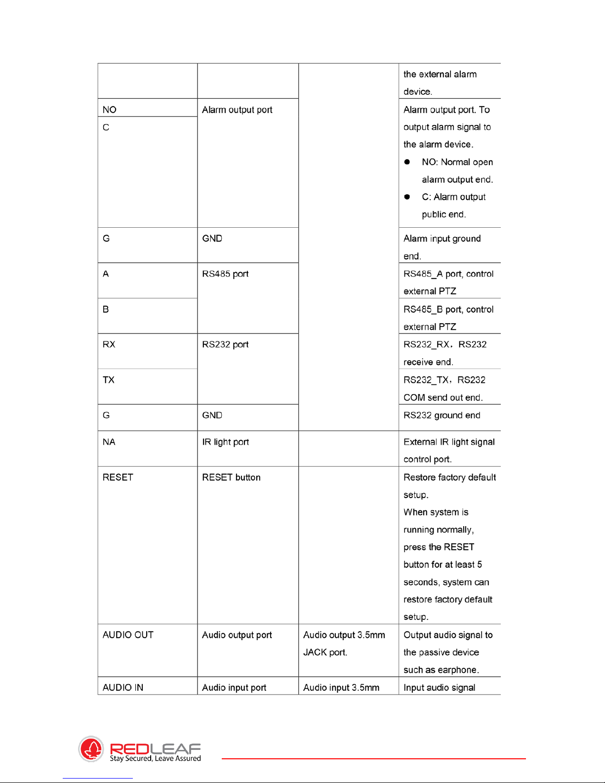
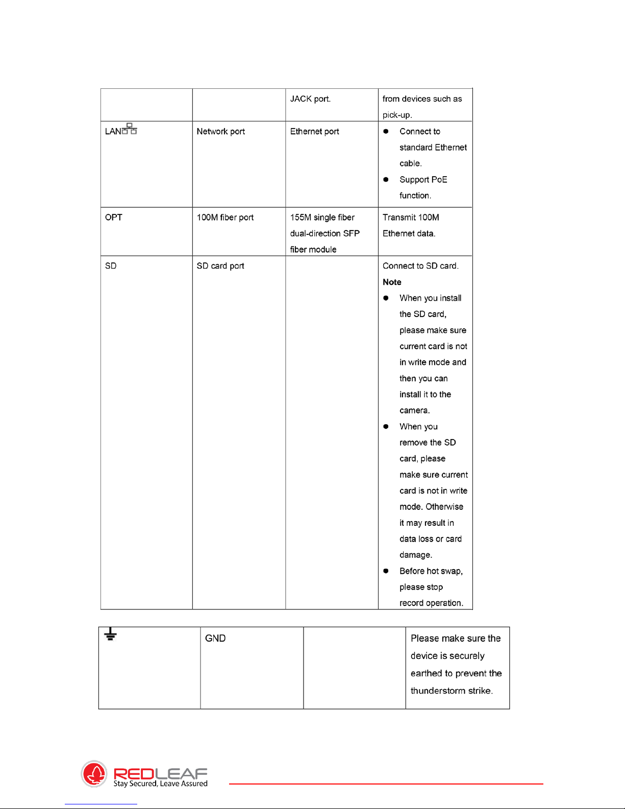
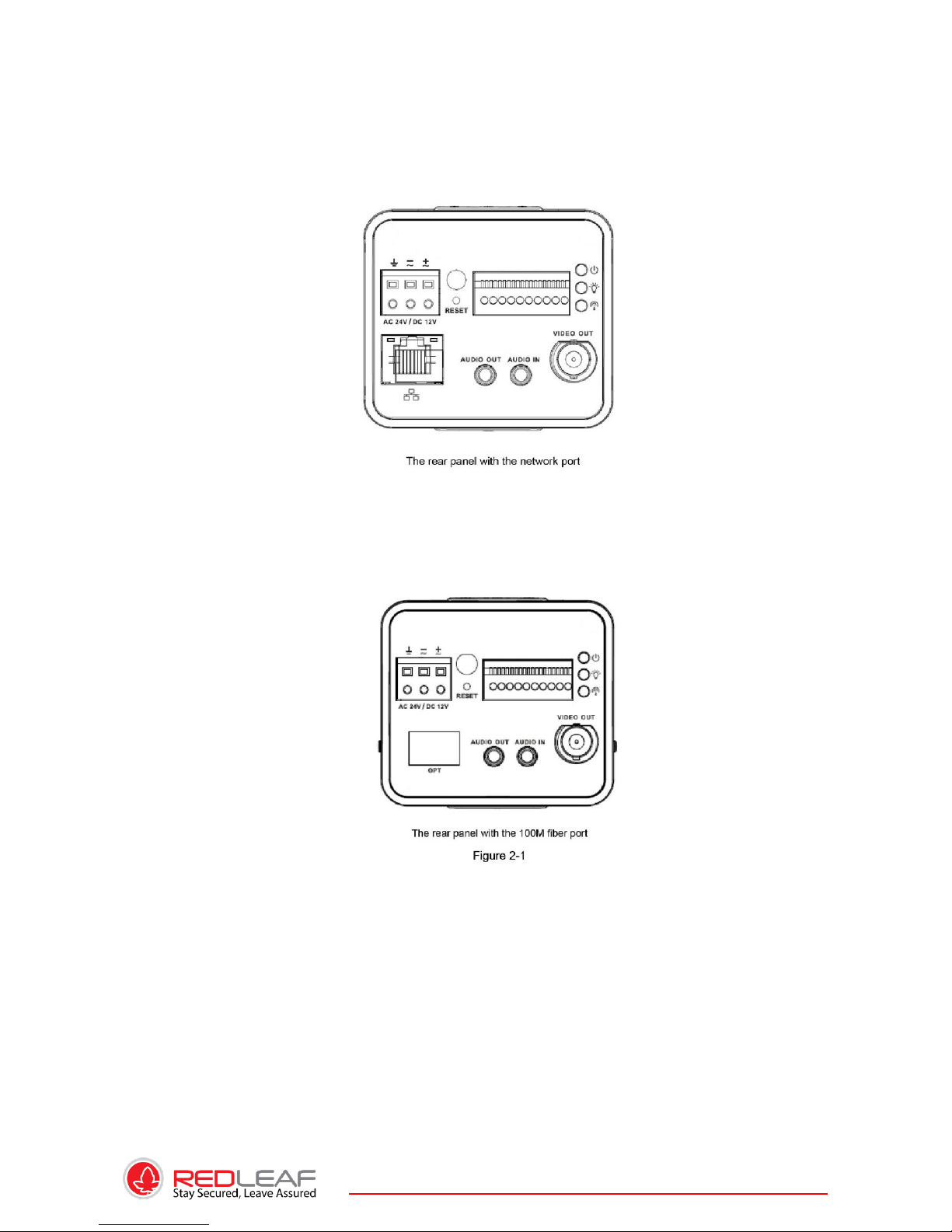
This series IP camera real panel is shown as below. See Figure 2-1.
Please refer to the following sheet for detail information.
Page 19
19
Page 20
20
Page 21
21
2.2. SIDE PANEL
Please refer to the following interface for side panel dimension information. The unit is mm.
See Figure 2-2.
2.3. FRONT PANEL
Please refer to the following interface for the front panel information. The unit is mm. See
Figure 2-3.
2.4. BIDIRECTIONAL TALK
2.4.1. DEVICE-END TO PC-END
Device Connection
Please connect the speaker or the MIC to the audio input port in the device rear panel.
Then connect the earphone to the audio output port in the PC. Login the Web and then
click the Audio button to enable the bidirectional talk function.
You can see the button becomes orange after you enabled the audio talk function. Click
Audio button again to stop the bidirectional talk function.
Page 22
22
Listening Operation at the device end, speak via the speaker or the pickup, and then you
can get the audio from the earphone or sound box at the pc-end.
2.4.2. PC-END TO THE DEVICE-END
Device Connection
Connect the speaker or the MIC to the audio input port in the PC and then
connect the earphone to the audio output port in the device rear panel.
Login the Web and then click the Audio button to enable the bidirectional talk function.
You can see the button becomes orange after you enabled the audio talk function. Click
Audio button again to stop the bidirectional talk function. Please note the listening
operation is null during the bidirectional talk process.
Listening Operation at the PC-end, speak via the speaker or the pickup, and then you
can get the audio from the earphone or sound box at the device-end.
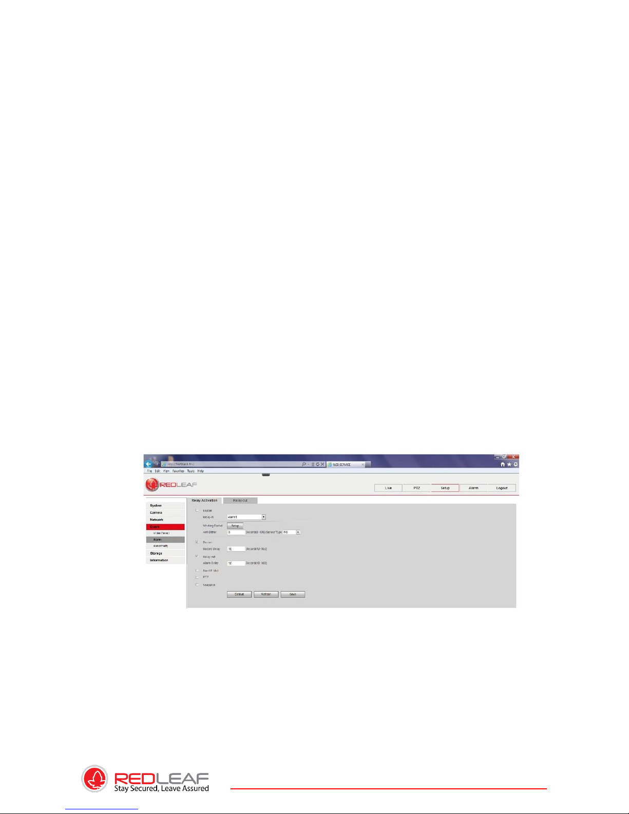
2.5. ALARM SETUP
The alarm setup interface is shown as below. See Figure 2-4.
Connect the alarm input device to the alarm input port.
Connect the alarm output device to the alarm output port and alarm output public port.
The alarm output port supports NO (normal open) alarm device only.
Open the Web, go to the Figure 2-4. Here you can set the alarm input setup and alarm
output setup. Please set the alarm in for the alarm input in the rear panel. Then you can
select the corresponding type (NO/NC) according to the high/low level type when an alarm
occurs. Set the WEB alarm output. The alarm output 01 is the alarm output port of the
device rear panel.
2.5.1. Alarm Input and Output Connection
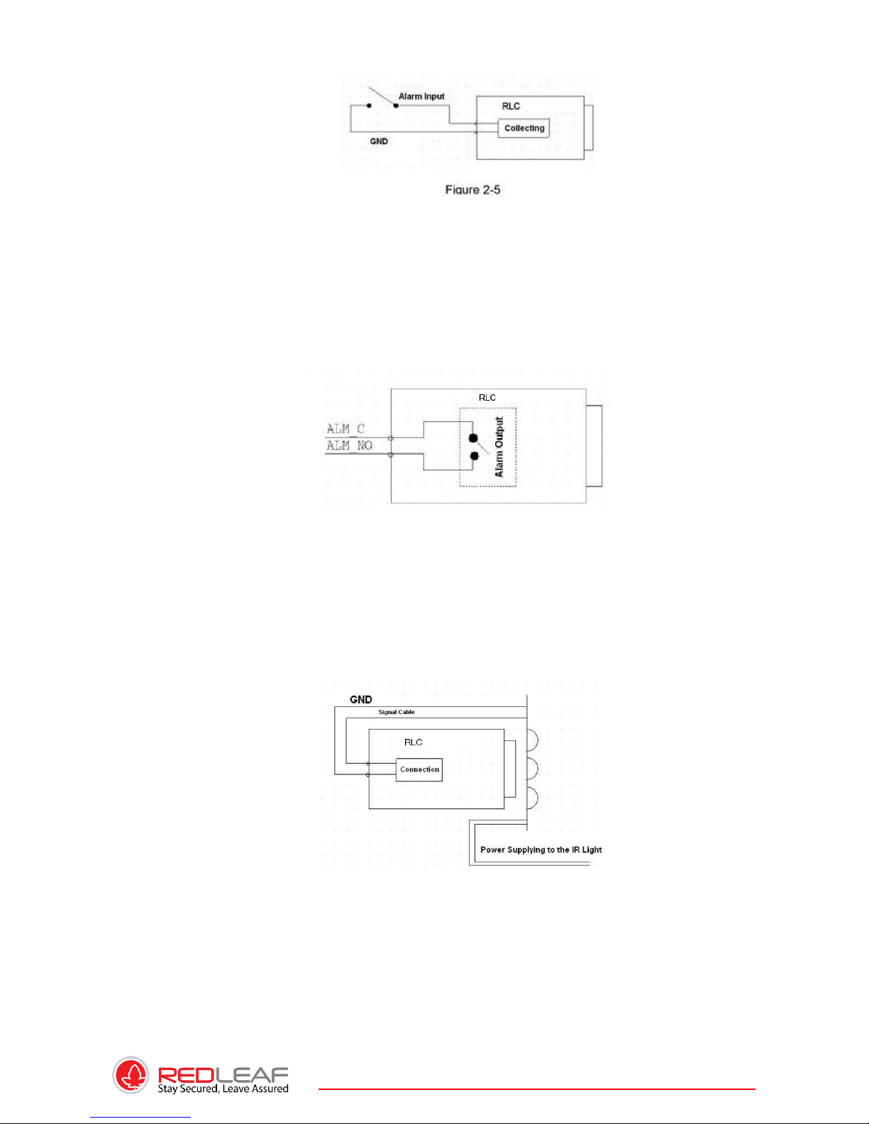
Please refer to the following figure for alarm input information. See Figure 2-5. Alarm
input: When the input signal is idle or grounded, the device can collect the different
statuses of the alarm input port. When the input signal is connected to the 5V or is idle,
the device collects the logic “1”. When the input signal is grounded, the device collects
the logic “0”.
Page 23
23
Please refer to the following figure for alarm output information. See Figure 2-6.
Port NO and Port C composes an on-off button to provide the alarm output. If the type
is NO, this button is normal open. The button becomes on when there is an alarm
output. If the type is NC, this button is normal off. The button becomes off when there is
an alarm output.
2.5.2. IR LIGHT CONNECTION
Please refer to the following figure for external IR light information.
See Figure 2-7. IR synchronization input signal. When the external IR light is on, the
signal cable from the board outputs the 3.3V/1mA. It outputs the 0V when the IR light is
off.
Page 24
24
3. INSTALLATION
3.1. Lens Installation
3.1.1. Auto Aperture Lens
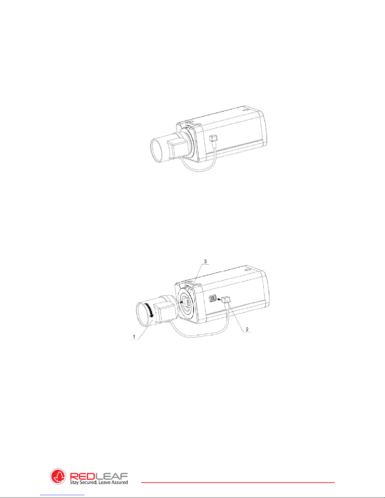
Please follow the steps listed below for auto aperture lens installation. The interface is
shown as in Figure 3-1 and Figure 3-2.
Remove the CCD protection cap of the device, and then line up the lens to the proper
installation position. Turn clockwise until the lens is fixed firmly. Insert the lens cable
socket to the auto lens connector in the side panel.
3.1.2. MANUAL LENS
Install C type lens
Remove the CCD protection cap from the device.
Install the C/CS adapter to the camera. Turn clockwise to secure against the focusing
ring firmly.
Line up the C lens to the installation position of the C/CS adapter. Turn clockwise to fix
the lens.
Use slotted screwdriver to fasten the screw near the focusing ring and then turn counter
clockwise to move the focusing ring out for several millimeters. Now you can focus
manually and check the video is clear or not. If you can’t see the clear video, you can
adjust via the flange-back. After you completed the focus setup, use the slotted
screwdriver to fix the screw firmly. Fasten the focusing ring. Now the installation
completed. Install CS type lens, remove the CCD protection cap from the device. Line up
the CS lens to the lens installation position of camera focusing ring. Turn clockwise to fix
the lens.
Page 25
25
Use slotted screwdriver to fasten the screw near the focusing ring and then turn counter
clockwise to move the focusing ring out for several millimeters.
Now you can focus manually and check the video is clear or not. If you can’t see the
clear video, you can adjust via the flange-back. After you completed the focus setup, use
the slotted screwdriver to fix the screw firmly. Fasten the focusing ring. Now the
installation completed.
3.1.3. REMOVE LENS
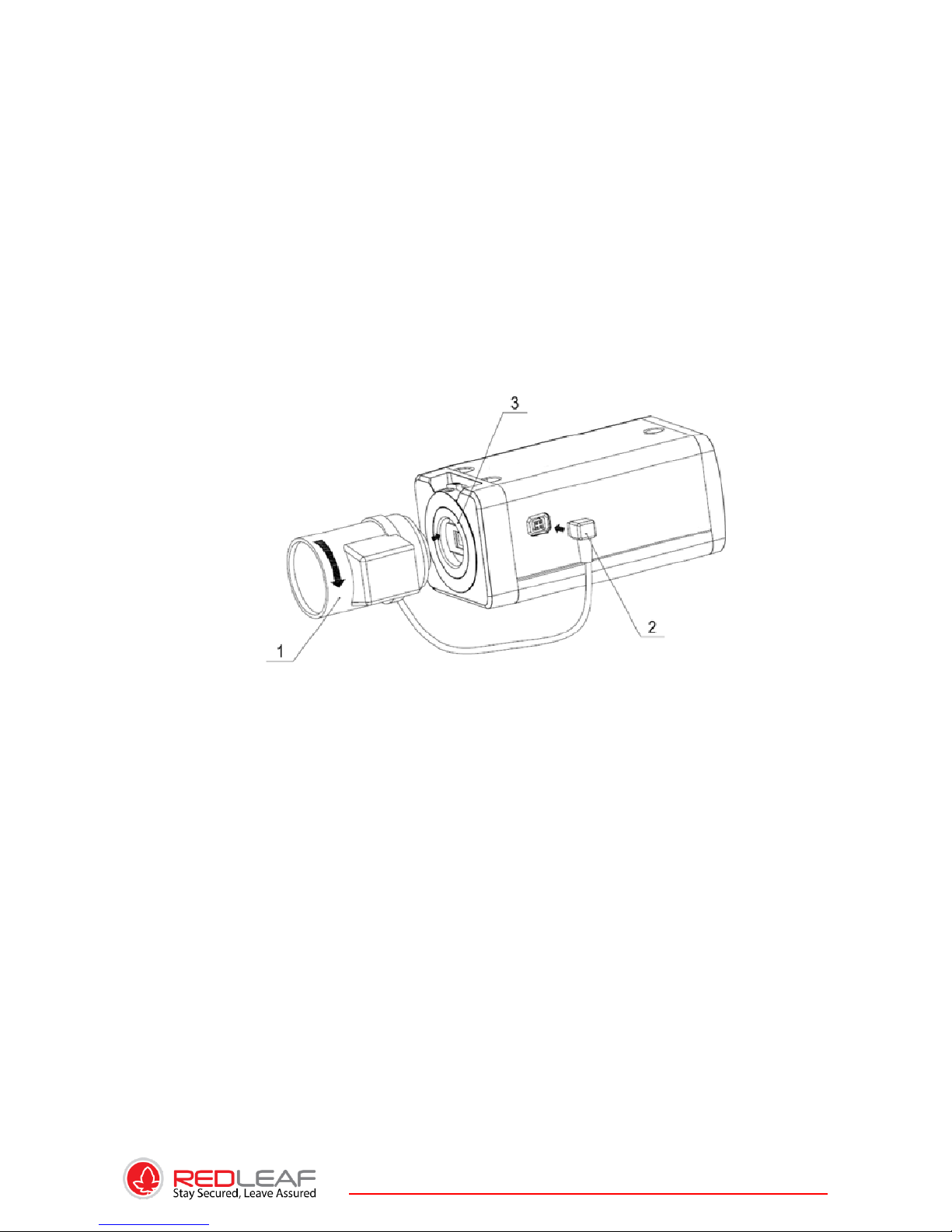
Please follow the steps listed below to remove lens. The interface is shown as in Figure
3-3. Turn the lens counter clockwise and then remove it from the camera.
Unplug the auto lens cable socket from the auto lens connector. If you are using the
manual aperture lens, please skip to the following step. If there is no lens, please put the
CCD protection cap back to protect the CCD.
3.2. SD CARD
3.2.1. INSTALLATION
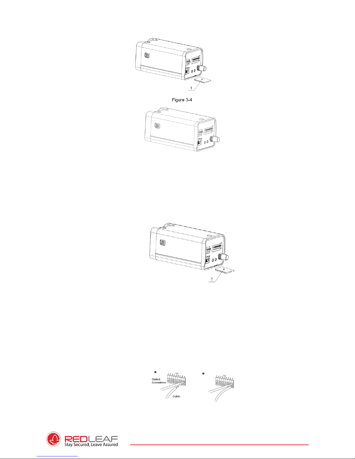
Please follow the steps listed below to install SD card. The interface is shown as in Figure
3-4 and Figure 3-5. Use the screwdriver to loosen the SD card protection screw in the
rear panel, and then remove the SD card protection cap from the camera. Install the SD
card to the camera according to the proper installation position. Put the SD card
protection cap back. Use the screwdriver to fix the SD card protection cap screw firmly
to secure the SD card protection cap in the camera.
Page 26
26
3.2.2. REMOVE
Please follow the steps listed below to remove SD card. The interface is shown as Figure
3-6. Use the screwdriver to loosen the screw of SD card protection cap in the rear panel.
Remove the cap from the camera.
Follow the SD card direction to remove the SD card. Insert the SD card protection cap.
Use the screwdriver to fix the screw to secure the protection cap.
3.2.3. I/O PORT
Install Cable
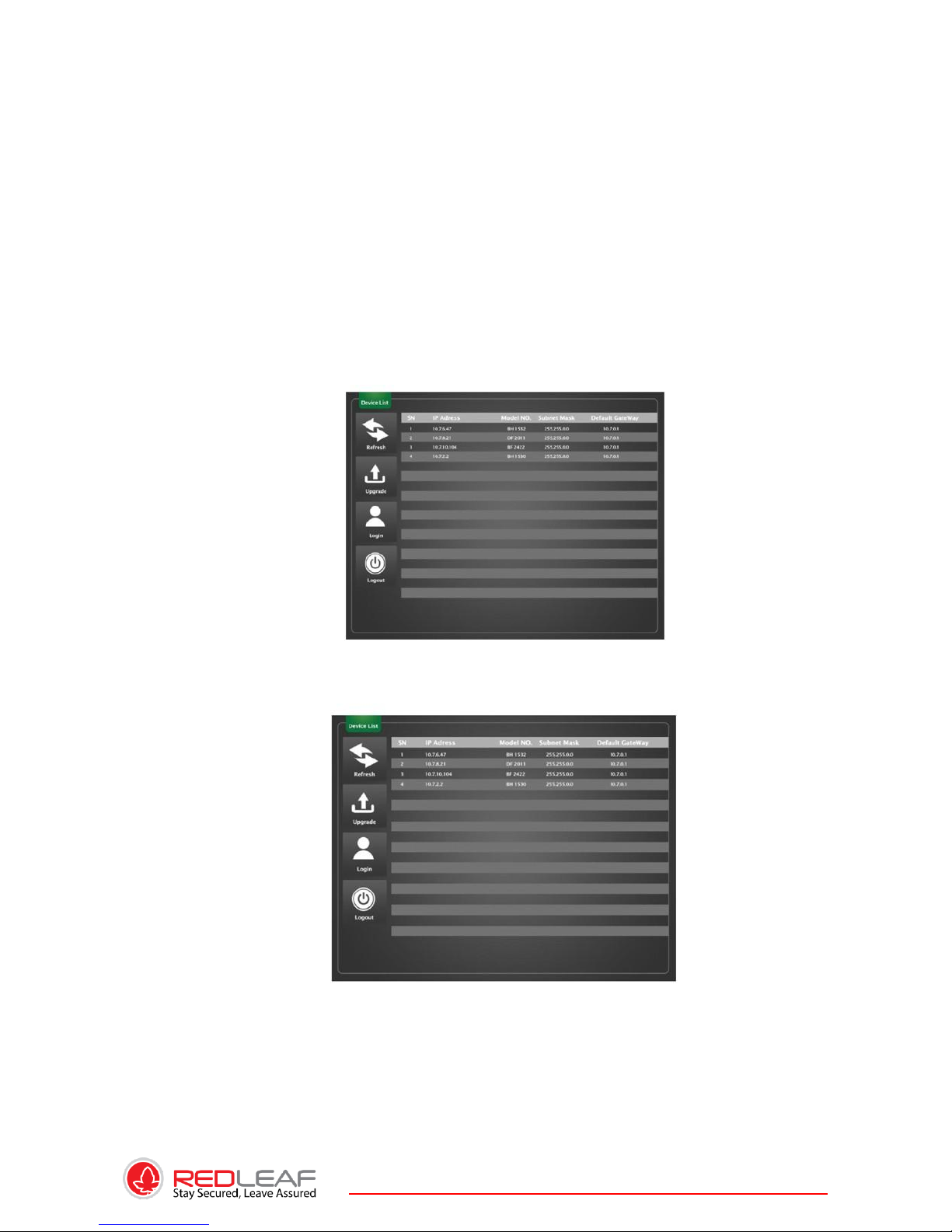
Please follow the steps listed below to install the cable. See Figure
3-16. Use the small slotted screwdriver to press the corresponding button of cable
groove. Insert the cable into the groove and then release the screwdriver.Remove
CablePlease follow the steps listed below to remove the cable.Use the small slotted
screwdriver to press the corresponding button of cable groove. Remove the cable out of
the groove and then release the screwdriver.
Page 27
27
4. QUICK CONFIGURATION TOOL
4.1. Overview
Quick configuration tool can search current IP address, modify IP address. At the same time,
you can use it to upgrade the device. Please note the tool only applies to the IP addresses in
the same segment.
4.2. Operation
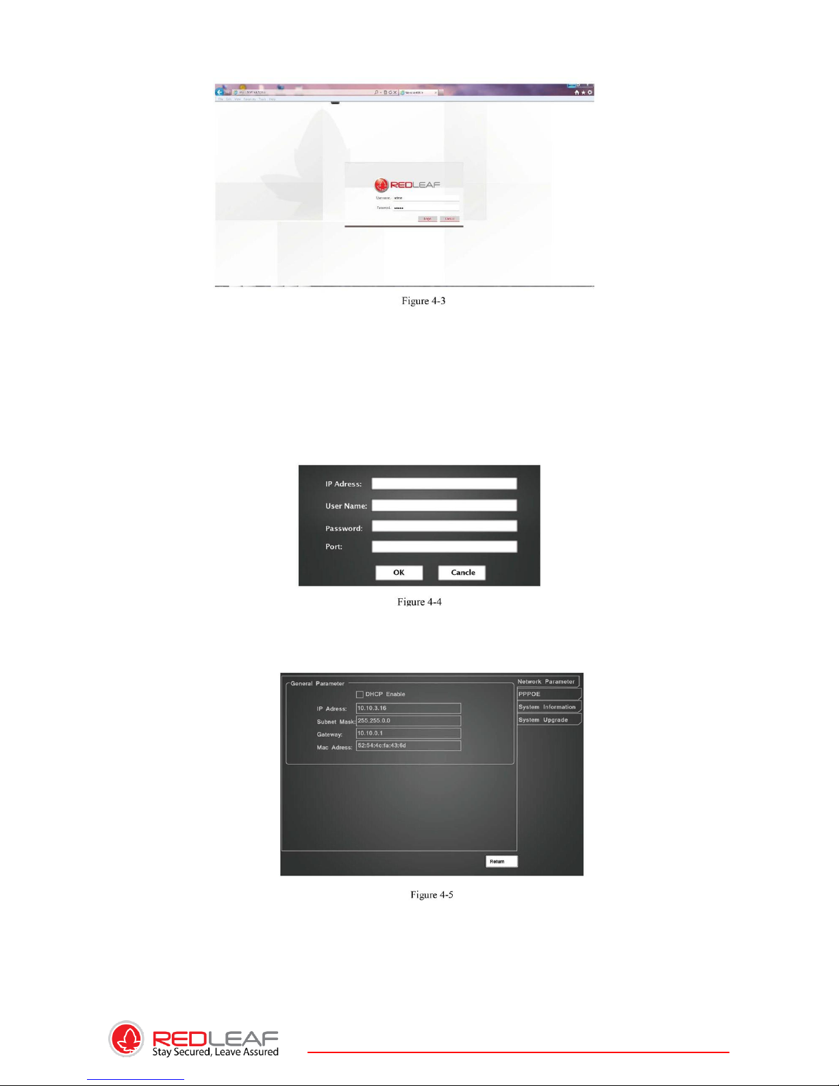
Double click the “ConfigTools.exe” icon, you can see an interface is shown as in Figure 4-1.
In the device list interface, you can view device IP address, port number, subnet mask,
default gateway, MAC address and etc.
Select one IP address and then right click mouse, you can see an interface is shown as in
Figure 4-2.
Select the “Open Device Web” item; you can go to the corresponding web login interface. See
Figure 4-3.
Page 28
28
If you want to modify the device IP address without logging in the device web interface, you can
go to the configuration tool main interface to set.
In the configuration tool search interface (Figure 4-1), please select a device IP address and
then double click it to open the login interface. Or you can select an IP address and then click
the Login button to go to the login interface. See Figure 4-4.
In Figure 4-4, you can view device IP address, user name, password and port. Please modify the
corresponding information to login.
For detailed information and operation instruction of the quick configuration tool, please refer
to the Quick Configuration Tool User’s Manual included in the resources CD.
Page 29
29
5. WEB OPERATION
This series RLC product support the Web access and management via PC. Web includes several
modules includes monitor channel preview, PTZ control, system configuration, alarm and etc.
IP camera factory default setup:
. IP address: 192.168.1.108.
. User name: admin
. Password: admin
5.1. NETWORK CONNECTION
Please follow the steps listed below for network connection.
. Make sure the RLC has connected to the network properly.
. Please set the IP address, subnet mask and gateway of the PC and the RLC respectively.
RLC default IP address is 192.168.1.108. Subnet mask is 255.255.255.0. Gateway is
192.168.1.1
. Use order ping ***.***.***.***(* IP camera address) to check connection is OK or
not.
5.2. LOGIN AND MAIN INTERFACE
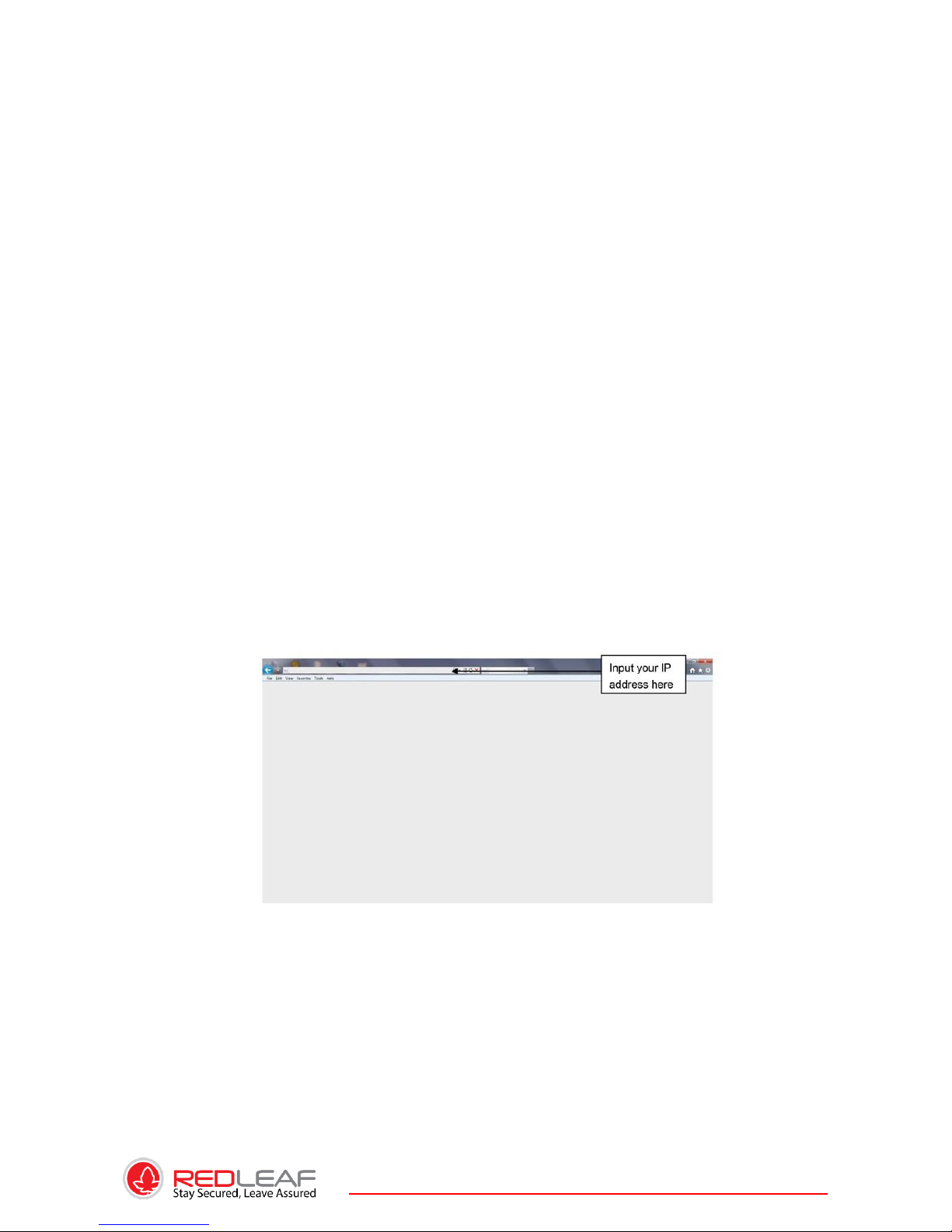
Open IE and input IP camera address in the address bar.
For example, if your camera IP is 192.168.1.108, then please input http:// 192.168.1.108 in
IE address bar. See Figure 5-1.
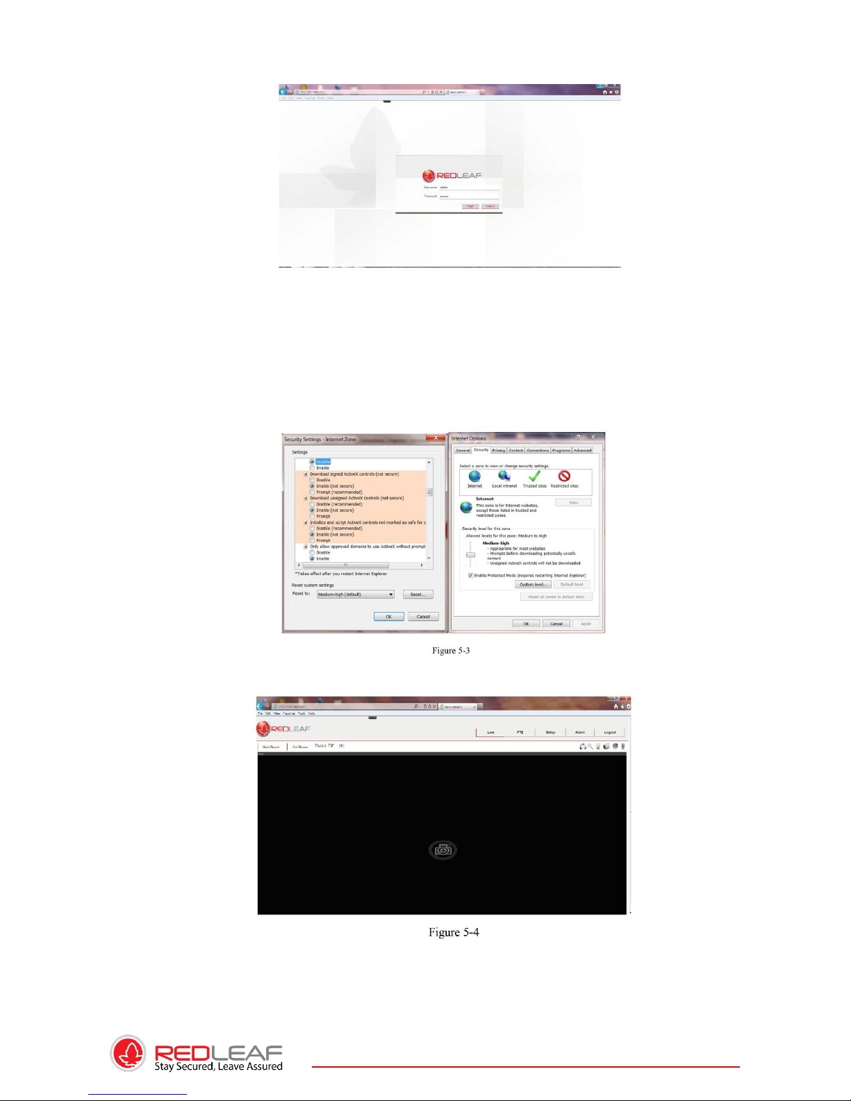
The login interface is shown as below. See Figure 5-2. Please input your user name and
password. Default factory name is admin and password is admin.
Note: For security reasons, please modify your password after you first login.
Page 30
30
If it is your first time to login in, system pops up warning information to ask you whether
install control webrec.cab or not after you logged in for one minute. Please click OK button,
system can automatically install the control. When system is upgrading, it can overwrite the
previous Web too.
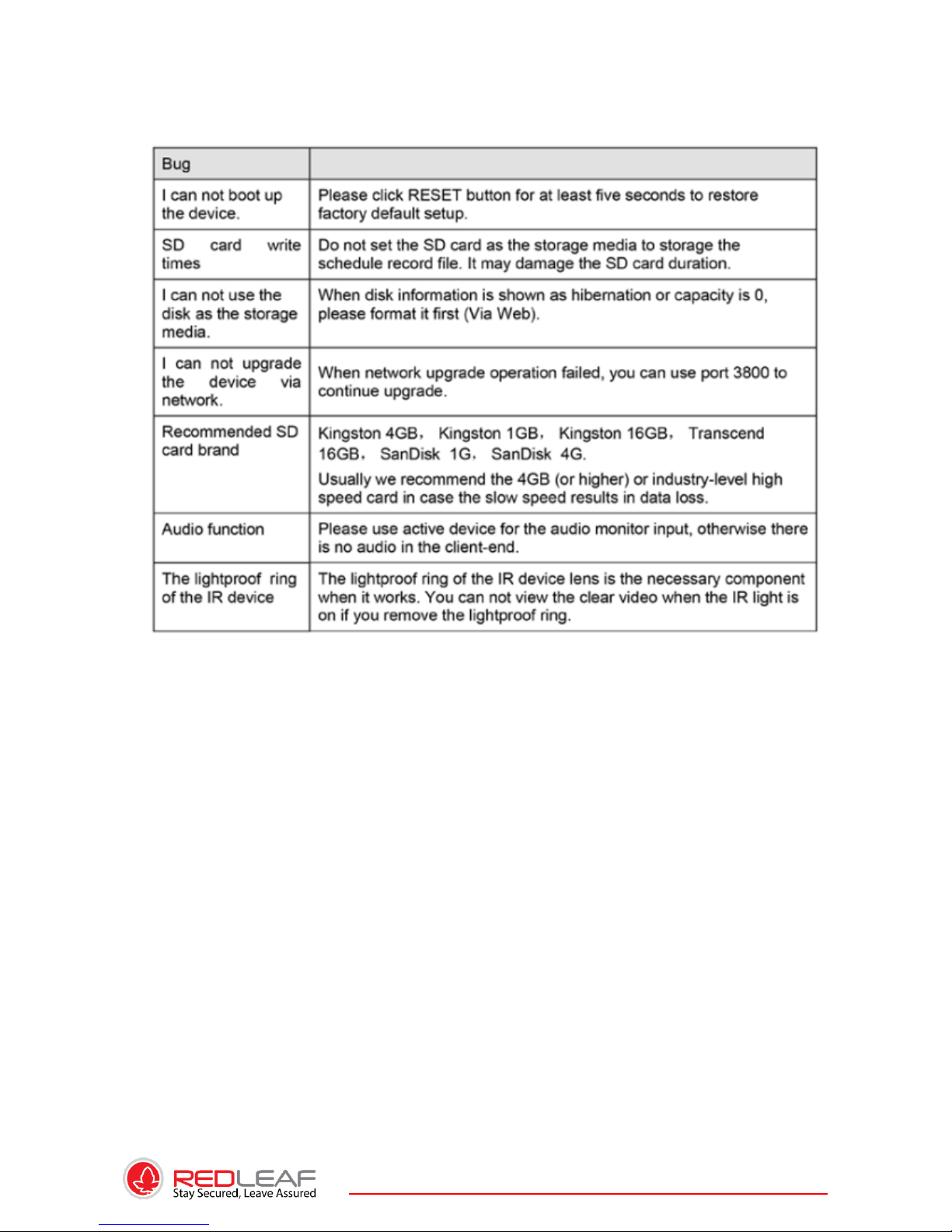
If you can’t download the ActiveX file, please check whether you have installed the plug-in
to disable the control download. Or you can lower the IE security level. See Figure 5-3.
After you logged in, you can see the main window. See figure 5-4.
Please refer to the Web Operation Manual included in the resource CD for detailed
operation instruction.
Page 31
31
6. FAQ
Page 32
32
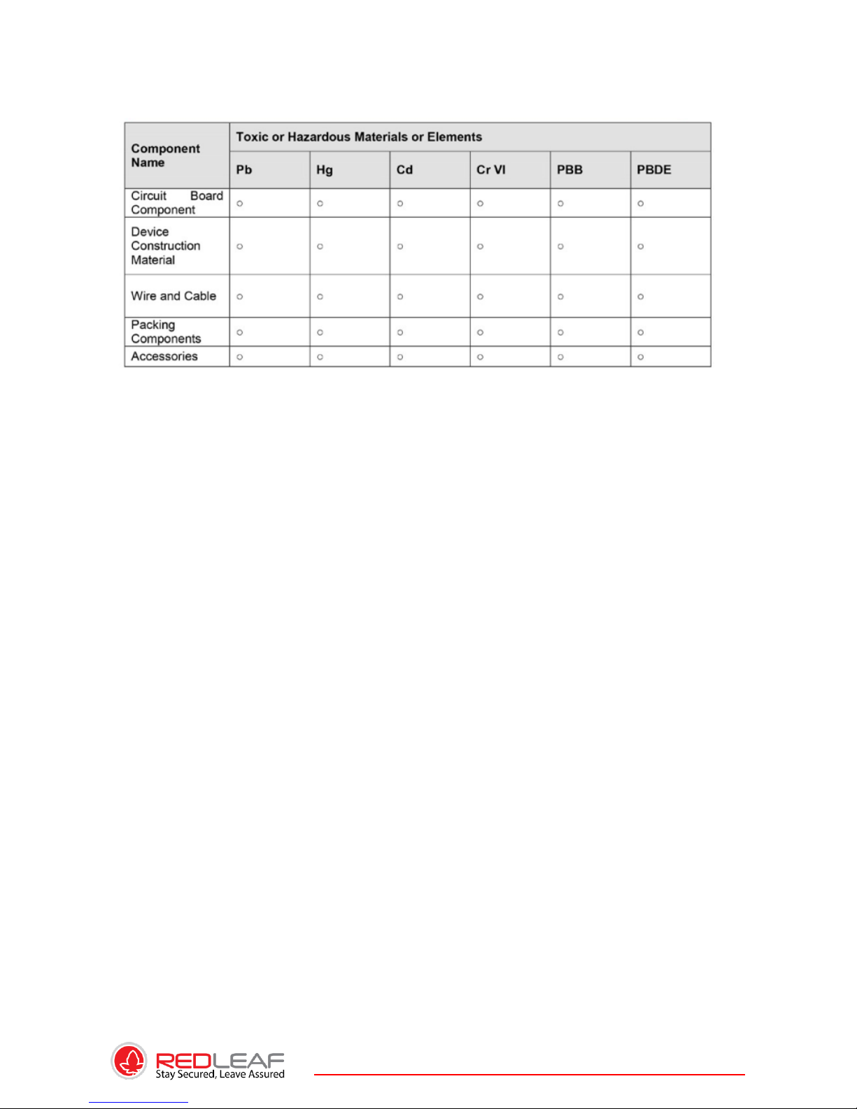
Appendix Toxic or Hazardous Materials or Elements
Note
O: Indicates that the concentration of the hazardous substance in all homogeneous materials in
the parts is below the relevant threshold of the SJ/T11363-2006 standard.
X: Indicates that the concentration of the hazardous substance of at least one of all
homogeneous materials in the parts is above the relevant threshold of the SJ/T11363-2006
standard. During the environmental-friendly use period (EFUP) period, the toxic or hazardous
substance or elements contained in products will not leak or mutate so that the use of these
(substances or elements) will not result in any severe environmental pollution, any bodily injury
or damage to any assets. The consumer is not authorized to process such kind of substances or
elements, please return to the corresponding local authorities to process according to your
local government statutes.
Note
• This manual is for reference only. Slight difference may be found in the user interface.
• All the designs and software here are subject to change without prior written notice.
• All trademarks and registered trademarks are the properties of their respective owners.
• If there is any uncertainty or controversy, please refer to the final explanation of us.
• Please visit our website or contact your local service engineer for more information.
Page 33

33
About RedLeaf Company:
RedLeaf is a Canadian-based IT company
offering state-of-the-art network security
products fulfilling customers’ needs for
cutting edge security technologies.
Founded in 2002, RedLeaf internationally
provides professional IP based video
security solutions for surveillance, remote
monitoring and other security
applications,including network security
cameras, video servers, video decoders,
video management software and related
accessories.
 Loading...