

Page 1

2.00 (50.8)
1.10 (27.9)
0.11 (2.8)
0.10 (2.5)
1.56 (39.6)
0.87 (22.0)
0.874
1.77
(22.2 )
(45 )
+0.024
-0.000
+0.6
-0.0
+0.012
-0.000
+0.3
-0.0
85374216
Bulletin No. CUB7T0-D
Drawing No. LP0648
Released 6/09
Tel +1 (717) 767-6511
Fax +1 (717) 764-0839
www.redlion.net
MODEL CUB7T0 PROGRAMMABLE GENERAL PURPOSE ELECTRONIC TIMER
9 PROGRAMMABLE TIMER RANGES
3 (8 Digit 0.35") LCD DISPLAY OPTIONS (Reflective, Red
Transmissive, Yellow/Green Transmissive) with “Timer Active”
annunciator
CONTACT INPUT
REPLACEABLE INTERNAL LITHIUM BATTERY (provides up to 6
years of uninterrupted operation)
BOTH FRONT PANEL PROGRAM AND RESET BUTTONS ARE
INDIVIDUALLY ENABLED
WIRE CONNECTIONS VIA SCREW CLAMP TYPE TERMINALS
FRONT PANEL AND REMOTE RESET INPUT
NEMA 4X/IP65 SEALED FRONT BEZEL
DESCRIPTION
The CUB7T0 is an 8-digit miniature programmable timer with large 0.35
inch (8.90 mm) high digits. It has an LCD read-out available in Positive Image
Reflective (CUB7T000), Negative Image Transmissive with yellow/green
backlighting (CUB7T010) or red backlighting (CUB7T020). The backlight
versions require an external 9 to 28 VDC power supply. The display will wrap
around from a full display of “99999999” to “00000000” when an overflow
occurs. An annunciator, located in the upper left hand corner of the display,
blinks at 2 Hz when the signal input is activated. The CUB7T0 operates from
a switch contact or an open collector NPN transistor.
The CUB7T timers use a CMOS LSI chip, mounted on a gold-plated
substrate, that is electrically connected by ultrasonic wire-bonding. Proven
micro-electronic assembly and manufacturing techniques provide these units
with the reliability and dependability required for industrial service.
The CUB7T series is housed in a lightweight, high impact plastic case with
a clear viewing window. The sealed front panel with the silicone rubber buttons
meets NEMA 4X/IP65 specifications for wash-down and/or dusty environments,
when properly installed.
SAFETY SUMMARY
All safety related regulations, local codes and instructions that appear in the
manual or on equipment must be observed to ensure personal safety and to
prevent damage to either the instrument or equipment connected to it. If
equipment is used in a manner not specified by the manufacturer, the protection
provided by the equipment may be impaired.
Do not use this unit to directly command motors, valves, or other actuators
not equipped with safeguards. To do so, can be potentially harmful to persons
or equipment in the event of a fault to the unit.
CAUTION: Risk of Danger.
Read complete instructions prior to
installation and operation of the unit.
SPECIFICATIONS
1. DISPLAY: 8-digit LCD, 0.35" (8.90 mm) high digits.
2. POWER SOURCE: Replaceable Internal 3.0 V lithium battery to provide up
to 6 years of continuous operation. (Battery life is dependent upon usage.
Contacts that remain closed for long periods of time reduce battery life.)
3. BACKLIGHT POWER REQUIREMENTS: 9 to 28 VDC; 35 mA. typical,
50 mA max. Above 26 VDC, derate max. operating temperature to 40°C.
Must use a NEC Class 2 or SELV rated power supply.
4. ANNUNCIATOR: Annunciator in the upper left corner of the display flashes
at a 2 Hz rate when the signal input is activated.
5. SIGNAL INPUT: (LS terminal #4)
Contact Input (CUB7T0xx): Switch Contact or solid state Transistor Switch
to Common. Contact burden 15 μA max. A maintained closed switch to
COM will actuate the timer.
6. REMOTE RESET: 15 msec min. pulse width (active low) from 3.0 V
bipolar output, an open collector transistor, or a switch contact to common.
7. ACCURACY: 0.025%
8. ENVIRONMENTAL CONDITIONS:
Operating Temperature Range: 0 to 50 °C Derate max. operating
temperature to 40 °C above 26 VDC (Backlight versions).
Storage Temperature: -30 to 80 °C
Operating and Storage Humidity: 85% max. relative humidity (non-
condensing) from 0 °C to 50 °C.
Vibration According to IEC 68-2-6: Operational 5 to 500 Hz, in X, Y, Z
direction for 1.5 hours, 5 g’s.
Shock According to IEC 68-2-27: Operational 30 g's, 11 msec in 3 directions.
Altitude: Up to 2000 meters
9. CONNECTIONS: Wire clamping screw terminals.
Wire Strip Length: 0.3" (7.5 mm)
Wire Gage: 30-14 AWG copper wire
Torque: 5 inch-lbs (0.565 N-m) max
10. CERTIFICA TIONS AND COMPLIANCES:
SAFETY
Type 4X Indoor Enclosure rating (Face only)
DIMENSIONS In inches (mm)
Note: Recommended minimum clearance (behind the panel) for mounting clip installation is
2.15" (53.4) H x 3.00" (140) W.
PANEL CUT-OUT
1
Page 2

IEC-61010-1, EN 61010-1: Safety requirements for electrical equipment
PGM RST
ANNUNCIATOR
HS-6
+V-2
LS-4
3-RST EN
1-COM
5-RST
LATCHING
FEATURE
BEZEL
GASKET
0.062"
(1.57 mm)
THICK
EXISTING
PANEL
0.05" to 0.20"
(1.3 to 5.1 mm)
THICK
MOUNTING
SCREW
MOUNTING
CLIP
for measurement, control, and laboratory use, Part 1.
IP65 Enclosure rating (Face only), IEC 529
ELECTROMAGNETIC COMPATIBILITY
Immunity to EN 50082-2
Electrostatic discharge EN 61000-4-2 Level 2; 4 Kv contact
Level 3; 8 Kv air
Electromagnetic RF fields EN 61000-4-3 Level 3; 10 V/m
80 MHz - 1 GHz
Fast transients (burst) EN 61000-4-4 Level 4; 2 Kv I/O
Level 3; 2 Kv power
RF conducted interference EN 61000-4-6 Level 3; 10 V/rms
150 KHz - 80 MHz
Simulation of cordless telephone ENV 50204 Level 3; 10 V/m
900 MHz ± 5 MHz
200 Hz, 50% duty cycle
1
Emissions to EN 50081-1
RF interference EN 55022 Enclosure class B
Notes
1. Backlit powered units require a power line filter to be installed,
RLC LFIL0000 or equivalent, so as not to impair the function of the
backlighting.
Refer to EMC Installation Guidelines for additional information.
11. CONSTRUCTION: High impact plastic case with clear viewing window.
The front panel meets NEMA 4X/IP65 requirements for indoor use when
properly installed. Installation Category I, Pollution Degree 2. Panel gasket
and mounting clip included.
12. WEIGHT: 2 oz. (57 grams) [with battery]
INSTALLATION
The CUB7T meets NEMA 4X/IP65 requirements for indoor use when
properly installed. The units are intended to be mounted into an enclosed
panel. The viewing window and reset button are factory sealed for a
washdown environment. A sponge rubber gasket and mounting clip are
provided for installing the unit in the panel cut-out.
Installation Environment
The unit should be installed in a location that does not exceed the
maximum operating temperature and provides good air circulation. Placing
the unit near devices that generate excessive heat should be avoided.
The bezel should be cleaned only with a soft cloth and neutral soap
product. Do NOT use solvents.
Continuous exposure to direct sunlight may accelerate the aging process of
the bezel.
Do not use tools of any kind (screwdrivers, pens, pencils, etc.) to operate
the push buttons of the unit.
TIMER RANGE SELECTION
The CUB7T’s timer range can be modified in the Program mode. The
Program mode uses the PGM button (refer to photo) to switch between
Program and Operate modes. The RESET button (refer to photo) is used to
select the desired timer range.
Note: Timer range and accumulated time on the display will be lost if the
battery is removed from the unit
Connect wires between RST EN (Reset Enable) and COM. (Common); and
between HS (Program Enable) and COM. (Common) to enable front push
buttons. Press the PGM button to enter Program Mode, allowing selection of
the desired timer range. The display will show 00000.000 (Timer Range 0.001
sec). Repeatedly pressing the RST button will cycle through the available timer
ranges as shown in the table.
When the desired timer range is
displayed, press PGM to load the
range and return to operating
mode. (The CUB7T will remain
in Program Mode until the PGM
button is pressed.) Remove the
wire from the HS (Program
Enable) terminal to prevent
accidental changes to the timer
range. Any new time accumulated
will be at the new rate selected.
Note: To avoid incorrect display
information, it is recommended
that the CUB7T be reset after
making programming changes.
DISPLAY DURING
PROGRAMMING
00000.000 0.001 Sec
111111.11 0.01 Sec
2222222.2 0.1 Sec
33333333 1 Sec
4444444.4 0.1 Min
55555555 1 Min
666666.66 0.01 Hr
7777777.7 0.1 Hr
88888888 1 Hr
9999.99.99 Factory Use Only
Timer Range
The following procedure assures proper installation:
1. Cut panel opening to specified dimensions. Remove burrs and clean
around panel opening.
2. Carefully remove and discard the center section of the gasket.
3. Slide the panel gasket over the rear of the counter body to the back of the
bezel. Install CUB7T unit through the panel cut-out.
4. Insert the mounting screws onto both sides of mounting clip. Tip of screw
should NOT project from hole in mounting clip.
5. Slide the mounting clip over the rear of the unit until the clip is against the
back of the panel. The mounting clip has latching features which engage
into mating features on the CUB7T housing.
6. Note: It is necessary to hold the unit in place when sliding mounting clip
into position.
7. Alternately tighten each screw to ensure uniform gasket pressure.
Visually inspect the front panel gasket. The gasket should be compressed
to about 75 to 80% of its original thickness. If not, gradually turn mounting
screws to further compress gasket.
8. If the gasket is not adequately compressed and the mounting screws can no
longer be turned, loosen mounting screws, and check that the mounting
clip is latched as close as possible to the panel.
9. Repeat from step #5 for tightening mounting screws.
TROUBLESHOOTING
For further technical assistance, contact technical support at the appropriate
company numbers listed.
2
Page 3

BATTERY INSTALLATION
HS-6
V+-2
LS-4
5-RST
3-RST EN
1-COM
-+
4-LS
2-V+
6-HS
3-RST EN
1-COM
5-RST
TOP OF
UNIT
BATTERY COVER-
Push up to
unlatch cover.
+3V
MICRO
CHIP
COM
.01µf
220K
220K
BATT.
3.0V
LS
COM/NEUTRAL
T
LS
COM
LS
COM
LS
COM
SWITCH
CONTACT
INPUT
NPN
O.C. TRANSISTOR
OR (N) FET
INPUT
PNP
O.C. TRANSISTOR
OR (P) FET
INPUT
HS-6
V+-2
5-RST
1-COM
3-RST EN
LS-4
SIGNAL
INPUT
PROGRAM
ENABLE
1. Remove all power to the unit before removing battery cover.
2. To remove the battery cover, push upward in the direction of the arrow on
the rear cover (See drawing at right), until the cover unlatches. Pull the
cover straight out from unit to fully remove.
3. Remove old battery* and replace it with an RLC battery (BNL10000).
Observe proper polarity when replacing the battery as shown in the drawing.
4. Replace the cover. The battery cover is keyed so that it cannot be placed
upside down. The arrow on the rear of the cover should point toward the top
of the CUB7T when properly installed.
* - Dispose of properly.
WARNING: Lithium battery may explode if incinerated.
EMC INSTALLATION GUIDELINES
Although this unit is designed with a high degree of immunity to
ElectroMagnetic Interference (EMI), proper installation and wiring methods
must be followed to ensure compatibility in each application. The type of the
electrical noise, source or coupling method into the unit may be different for
various installations. In extremely high EMI environments, additional measures
may be needed. The unit becomes more immune to EMI with fewer I/O
connections. Cable length, routing and shield termination are very important
and can mean the difference between a successful or a troublesome installation.
Listed below are some EMC guidelines for successful installation in an
industrial environment.
1. Use shielded (screened) cables for all Signal and Control inputs. The shield
(screen) pigtail connection should be made as short as possible. The
connection point for the shield depends somewhat upon the application.
Listed below are the recommended methods of connecting the shield, in order
of their effectiveness.
a. Connect the shield only at the panel where the unit is mounted to earth
ground (protective earth).
b. Connect the shield to earth ground at both ends of the cable, usually when
the noise source frequency is above 1 MHz.
c. Connect the shield to common of the unit and leave the other end of the
shield unconnected and insulated from earth ground.
2. Never run Signal or Control cables in the same conduit or raceway with AC
power lines, conductors feeding motors, solenoids, SCR controls, and
heaters, etc. The cables should be run in metal conduit that is properly
grounded. This is especially useful in applications where cable runs are long
and portable two-way radios are used in close proximity or if the installation
is near a commercial radio transmitter.
3. Signal or Control cables within an enclosure should be routed as far away as
possible from contactors, control relays, transformers, and other noisy
components.
4. In extremely high EMI environments, the use of external EMI suppression
devices, such as ferrite suppression cores, is effective. Install them on Signal
and Control cables as close to the unit as possible. Loop the cable through the
core several times or use multiple cores on each cable for additional
protection. Install line filters on the power input cable to the unit to suppress
power line interference. Install them near the power entry point of the
enclosure. The following EMI suppression devices (or equivalent) are
recommended:
L.S. INPUT; CONTACT VERSIONS
Ferrite Suppression Cores for signal and control cables:
Fair-Rite # 0443167251 (RLC #FCOR0000)
TDK # ZCAT3035-1330A
Steward #28B2029-0A0
Line Filters for input power cables:
Schaffner # FN610-1/07 (RLC #LFIL0000)
Schaffner # FN670-1.8/07
Corcom #1VR3
Note: Reference manufacturer’s instructions when installing a line filter.
5. Long cable runs are more susceptible to EMI pickup than short cable runs.
Therefore, keep cable runs as short as possible.
WIRING CONNECTIONS
The electrical connections are made via screw-clamp terminals located on the
back of the unit. All conductors should meet voltage and current ratings for each
terminal. Also, cabling should conform to appropriate standards of good
installation, local codes and regulations. It is recommended that power supplied
to the unit be protected by a fuse or circuit breaker. When wiring the unit, use
the battery cover to identify the wire position with the proper function. Strip the
wire, leaving approximately 1/4" bare wire exposed (stranded wires should be
tinned with solder). Insert the wire under the screw-clamp and tighten down the
screw until the wire is clamped in tightly. Each terminal can accept up to two
#14 AWG wires.
WARNING: Lithium battery may explode if incinerated.
Connecting the “L.S.” Input to Common with a mechanical or solid-state
switch activates the timer. Releasing the connection, deactivates the timer. The
switch load is 15 A (max. voltage drop 0.5 V) when ON. The OFF-state
leakage current must be less than 2 A.
Reed switches, mercury wetted contacts, snap action limit switches, and
silver alloy relay contacts with wiping action are usually satisfactory for input
activation. Motor starter contacts, tungsten contacts, and brush-type contacts
should not be used.
3
Page 4
RESET AND PROGRAM OPTIONS
+3V
MICRO
CHIP
COM
0.022µF
220K
220K
BATT.
3.0V
RST.
COM/NEUTRAL
R
RST. EN.
FRONT
PANEL
RESET
HS
PROGRAM
REMOTE
RESET
P
HS-6
V+-2
5-RST
1-COM
3-RST EN
LS-4
CONTACT
CLOSURE
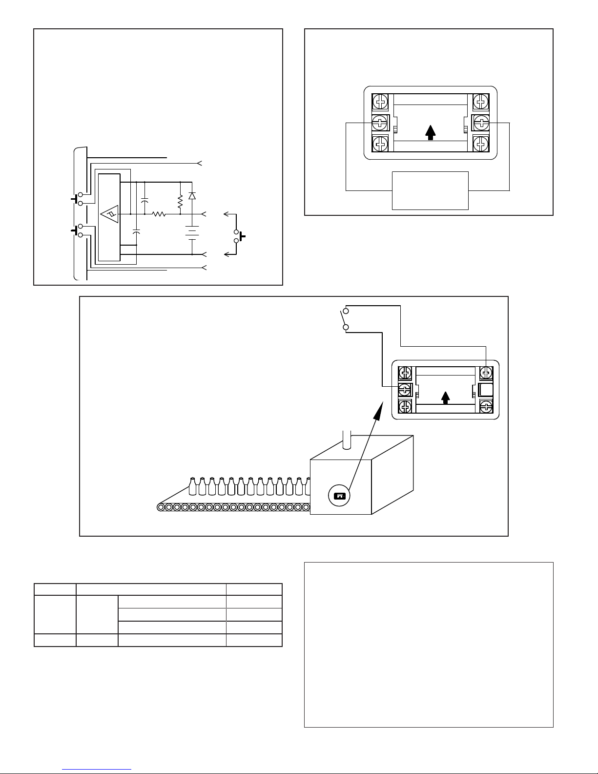
Connecting a wire from the RST EN (Reset Enable) or the HS (Program
Enable) Input terminals to Common will enable the front panel Reset or
Program buttons respectively.
Pulling the “RST.” input low causes the timer to reset. The “RST.” can be
pulled low by either a mechanical switch or solid-state transistor switch. The
Switch load is 15 μA (max. voltage drop 0.5 V) when ON. The OFF-state
leakage current must be less than 2 μA.
Note: The RC protection circuit on the “RST.” Input causes a delay of
approximately 15 msec in Reset response.
BACKLIGHT OPTION
Optional backlight versions of the CUB7T require an external 9 to 26
VDC power supply. The external supply is connected between the V+ and
common terminals as shown in the drawing.
3-RST EN
1-COM
5-RST
LS-4
V+-2
HS-6
APPLICATION
A bottling company has a preventive maintenance program
based on the accumulative running hours. For each bottling
line, they added a CUB7T000. When the line is running a
contact closure is given to the CUB7T timer allowing the new
time to accumulate with the hours of previous operations. At a
designated value, the line maintenance is performed and the
CUB7T is reset with a key switch to 0.
9-26 VDC
-
POWER SUPPLY
(Backlighting)
+
ORDERING INFORMATION
MODEL NO. DESCRIPTION PART NUMBER
Timer; Positive Image Reflective CUB7T000
*CUB7T
CONTACT
INPUT
Timer, w/Yel-Grn Backlighting CUB7T010
Timer; w/Red Backlighting CUB7T020
BNL Replacement 3 V Lithium Battery BNL10000
*Battery is included with unit.
The Company warrants the products it manufactures against defects in materials and
LIMITED WARRANTY
workmanship for a period limited to two years from the date of shipment, provided the
products have been stored, handled, installed, and used under proper conditions. The
Company’s liability under this limited warranty shall extend only to the repair or
replacement of a defective product, at The Company’s option. The Company disclaims
all liability for any affirmation, promise or representation with respect to the products.
The customer agrees to hold Red Lion Controls harmless from, defend, and indemnify
RLC against damages, claims, and expenses arising out of subsequent sales of RLC
products or products containing components manufactured by RLC and based upon
personal injuries, deaths, property damage, lost profits, and other matters which Buyer,
its employees, or sub-contractors are or may be to any extent liable, including without
limitation penalties imposed by the Consumer Product Safety Act (P.L. 92-573) and
liability imposed upon any person pursuant to the Magnuson-Moss Warranty Act (P.L.
93-637), as now in effect or as amended hereafter.
No warranties expressed or implied are created with respect to The Company’s products
except those expressly contained herein. The Customer acknowledges the disclaimers
and limitations contained herein and relies on no other warranties or affirmations.
 Loading...