

Page 1

Red Hat Directory
Server 8.1
Deployment Guide
Ella Deon Lackey
Publication date: April 28, 2009, updated on September 9, 2009
Page 2

Deployment Guide
Deployment Guide
Author Ella Deon Lackey
Copyright © 2009 Red Hat, Inc.
Copyright © 2009 Red Hat, Inc.. This material may only be distributed subject to the terms and
conditions set forth in the Open Publication License, V1.0 or later (the latest version of the OPL is
presently available at http://www.opencontent.org/openpub/).
Red Hat and the Red Hat "Shadow Man" logo are registered trademarks of Red Hat, Inc. in the United
States and other countries.
All other trademarks referenced herein are the property of their respective owners.
1801 Varsity Drive
Raleigh, NC 27606-2072 USA
Phone: +1 919 754 3700
Phone: 888 733 4281
Fax: +1 919 754 3701
PO Box 13588 Research Triangle Park, NC 27709 USA
This manual covers the basic considerations that should be addressed before deploying Red Hat
Directory Server. The decisions made during this phase can have a significant and lasting affect
on the effectiveness, efficiency, and scalability of your Directory Server. You should have a good
understanding of your Directory Server requirements before moving on to the installation phase.
Page 3

iii
Preface v
1. Directory Server Overview ............................................................................................... v
2. Examples and Formatting ................................................................................................ v
3. Additional Reading ......................................................................................................... vii
4. Giving Feedback ........................................................................................................... viii
5. Documentation History .................................................................................................. viii
1. Introduction to Directory Services 1
1.1. About Directory Services .............................................................................................. 1
1.2. Introduction to Directory Server ..................................................................................... 2
1.3. Directory Server Data Storage ...................................................................................... 5
1.4. Directory Design Overview ............................................................................................ 6
1.5. Other General Directory Resources ............................................................................... 8
2. Planning the Directory Data 9
2.1. Introduction to Directory Data ....................................................................................... 9
2.2. Defining Directory Needs ............................................................................................ 10
2.3. Performing a Site Survey ............................................................................................ 10
2.4. Documenting the Site Survey ...................................................................................... 17
2.5. Repeating the Site Survey .......................................................................................... 18
3. Designing the Directory Schema 19
3.1. Schema Design Process Overview .............................................................................. 19
3.2. Standard Schema ....................................................................................................... 19
3.3. Mapping the Data to the Default Schema .................................................................... 22
3.4. Customizing the Schema ............................................................................................ 24
3.5. Maintaining Consistent Schema .................................................................................. 30
3.6. Other Schema Resources ........................................................................................... 31
4. Designing the Directory Tree 33
4.1. Introduction to the Directory Tree ................................................................................ 33
4.2. Designing the Directory Tree ....................................................................................... 33
4.3. Grouping Directory Entries .......................................................................................... 44
4.4. Virtual Directory Information Tree Views ...................................................................... 47
4.5. Directory Tree Design Examples ................................................................................. 53
4.6. Other Directory Tree Resources .................................................................................. 55
5. Designing the Directory Topology 57
5.1. Topology Overview ..................................................................................................... 57
5.2. Distributing the Directory Data ..................................................................................... 57
5.3. About Knowledge References ..................................................................................... 61
5.4. Using Indexes to Improve Database Performance ........................................................ 71
6. Designing the Replication Process 75
6.1. Introduction to Replication ........................................................................................... 75
6.2. Common Replication Scenarios ................................................................................... 78
6.3. Defining a Replication Strategy ................................................................................... 86
6.4. Using Replication with Other Directory Server Features ................................................ 95
7. Designing Synchronization 99
7.1. Windows Synchronization Overview ............................................................................ 99
7.2. Planning Windows Synchronization ........................................................................... 100
7.3. Schema Elements Synchronized Between Active Directory and Directory Server ........... 105
8. Designing a Secure Directory 111
Page 4

Deployment Guide
iv
8.1. About Security Threats ............................................................................................. 111
8.2. Analyzing Security Needs ......................................................................................... 112
8.3. Overview of Security Methods ................................................................................... 114
8.4. Selecting Appropriate Authentication Methods ............................................................ 115
8.5. Preventing Authentication by Account Deactivation ..................................................... 118
8.6. Designing a Password Policy .................................................................................... 118
8.7. Designing Access Control ......................................................................................... 125
8.8. Database Encryption ................................................................................................. 133
8.9. Securing Server to Server Connections ..................................................................... 134
8.10. Other Security Resources ....................................................................................... 134
9. Directory Design Examples 137
9.1. Design Example: A Local Enterprise .......................................................................... 137
9.2. Design Example: A Multinational Enterprise and Its Extranet ....................................... 143
Page 5

v
Preface
The Red Hat Directory Server Deployment Guide provides a solid foundation on the on concepts
and configuration options for planning an effective directory service. The information provided here is
intended for both designers and administrators.
1. Directory Server Overview
Red Hat Directory Server provides the following key features:
• Multi-master replication — Provides a highly available directory service for both read and write
operations. Multi-master replication can be combined with simple and cascading replication
scenarios to provide a highly flexible and scalable replication environment.
• Chaining and referrals — Increases the power of the directory by storing a complete logical view
of the directory on a single server while maintaining data on a large number of Directory Servers
transparently for clients.
• Roles and classes of service — Provides a flexible mechanism for grouping and sharing attributes
between entries dynamically.
• Efficient access control mechanisms — Provides support for macros that dramatically reduce the
number of access control statements used in the directory and increase the scalability of access
control evaluation.
• Resource-limits by bind DN — Grants the power to control the amount of server resources allocated
to search operations based on the bind DN of the client.
• Multiple databases — Provides a simple way of breaking down the directory data to simplify the
implementation of replication and chaining in the directory service.
• Password policy and account lockout — Defines a set of rules that govern how passwords and user
accounts are managed in the Directory Server.
• TLS and SSL — Provides secure authentication and communication over the network, using the
Mozilla Network Security Services (NSS) libraries for cryptography.
The major components of Directory Server include the following:
• An LDAP server — The LDAP v3-compliant network daemon.
• Directory Server Console — A graphical management console that dramatically reduces the effort of
setting up and maintaining the directory service.
• SNMP agent — Can monitor the Directory Server using the Simple Network Management Protocol
(SNMP).
2. Examples and Formatting
Each of the examples used in this guide, such as file locations and commands, have certain defined
conventions.
Page 6

Preface
vi
2.1. Command and File Examples
All of the examples for Red Hat Directory Server commands, file locations, and other usage are given
for Red Hat Enterprise Linux 5 (32-bit) systems. Be certain to use the appropriate commands and files
for your platform.
To start the Red Hat Directory Server:
service dirsv start
Example 1. Example Command
2.2. Tool Locations
The tools for Red Hat Directory Server are located in the /usr/bin and the /usr/sbin directories.
These tools can be run from any location without specifying the tool location.
2.3. LDAP Locations
There is another important consideration with the Red Hat Directory Server tools. The LDAP tools
referenced in this guide are Mozilla LDAP, installed with Red Hat Directory Server in the /usr/lib/
mozldap directory on Red Hat Enterprise Linux 5 (32-bit) (or /usr/lib64/mozldap for 64-bit
systems).
However, Red Hat Enterprise Linux systems also include LDAP tools from OpenLDAP in the /usr/
bin directory. It is possible to use the OpenLDAP commands as shown in the examples, but you must
use the -x argument to disable SASL, which OpenLDAP tools use by default.
2.4. Text Formatting and Styles
Certain words are represented in different fonts, styles, and weights. Different character formatting is
used to indicate the function or purpose of the phrase being highlighted.
Formatting Style Purpose
Monospace font Monospace is used for commands, package
names, files and directory paths, and any text
displayed in a prompt.
Monospace
with a
background
This type of formatting is used for anything
entered or returned in a command prompt.
Italicized text Any text which is italicized is a variable, such
as instance_name or hostname. Occasionally,
this is also used to emphasize a new term or
other phrase.
Bolded text Most phrases which are in bold are application
names, such as Cygwin, or are fields or
options in a user interface, such as a User
Name Here: field or Save button.
Other formatting styles draw attention to important text.
Page 7
Additional Reading
vii
NOTE
A note provides additional information that can help illustrate the behavior of the system or
provide more detail for a specific issue.
IMPORTANT
Important information is necessary, but possibly unexpected, such as a configuration
change that will not persist after a reboot.
WARNING
A warning indicates potential data loss, as may happen when tuning hardware for
maximum performance.
3. Additional Reading
The Directory Server Administrator's Guide describes how to set up, configure, and administer Red
Hat Directory Server and its contents. this manual does not describe many of the basic directory and
architectural concepts that you need to deploy, install, and administer a directory service successfully.
Those concepts are contained in the Red Hat Directory Server Deployment Guide. You should read
that book before continuing with this manual.
When you are familiar with Directory Server concepts and have done some preliminary planning for
your directory service, install the Directory Server. The instructions for installing the various Directory
Server components are contained in the Red Hat Directory Server Installation Guide. Many of the
scripts and commands used to install and administer the Directory Server are explained in detail in the
Red Hat Directory Server Configuration, Command, and File Reference.
Also, Managing Servers with Red Hat Console contains general background information on how to
use the Red Hat Console. You should read and understand the concepts in that book before you
attempt to administer Directory Server.
The document set for Directory Server contains the following guides:
• Red Hat Directory Server Release Notes contain important information on new features, fixed bugs,
known issues and workarounds, and other important deployment information for this specific version
of Directory Server.
• Red Hat Directory Server Deployment Guide provides an overview for planning a deployment of the
Directory Server.
• Red Hat Directory Server Administrator's Guide contains procedures for the day-to-day maintenance
of the directory service. Includes information on configuring server-side plug-ins.
• Red Hat Directory Server Configuration, Command, and File Reference provides reference
information on the command-line scripts, configuration attributes, and log files shipped with
Directory Server.
• Red Hat Directory Server Installation Guide contains procedures for installing your Directory Server
as well as procedures for migrating from a previous installation of Directory Server.
Page 8

Preface
viii
• Red Hat Directory Server Schema Reference provides reference information about the Directory
Server schema.
• Red Hat Directory Server Plug-in Programmer's Guide describes how to write server plug-ins in
order to customize and extend the capabilities of Directory Server.
• Using Red Hat Console gives an overview of the primary user interface and how it interacts with
the Directory Server and Administration Server, as well as how to perform basic management tasks
through the main Console window.
• Using the Admin Server describes the different tasks and tools associated with the Administration
Server and how to use the Administration Server with the Configuration and User Directory Server
instances.
For the latest information about Directory Server, including current release notes, complete product
documentation, technical notes, and deployment information, see the Red Hat Directory Server
documentation site at http://www.redhat.com/docs/manuals/dir-server/.
4. Giving Feedback
If there is any error in this Deployment Guide or there is any way to improve the documentation,
please let us know. Bugs can be filed against the documentation for Red Hat Directory Server through
Bugzilla, http://bugzilla.redhat.com/bugzilla. Make the bug report as specific as possible, so we can be
more effective in correcting any issues:
• Select the Red Hat Directory Server product.
• Set the component to Doc - deployment-guide.
• Set the version number to 8.1.
• For errors, give the page number (for the PDF) or URL (for the HTML), and give a succinct
description of the problem, such as incorrect procedure or typo.
For enhancements, put in what information needs to be added and why.
• Give a clear title for the bug. For example, "Incorrect command example for setup
script options" is better than "Bad example".
We appreciate receiving any feedback — requests for new sections, corrections, improvements,
enhancements, even new ways of delivering the documentation or new styles of docs. You are
welcome to contact Red Hat Content Services directly at docs@redhat.com1.
5. Documentation History
Revision 8.1.2 September 9, 2009 Ella Deon Lackey
Removing any references to the Directory Server Gateway or Org Chart.
Revision 8.1.1 April 28, 2009 Ella Deon Lackey dlackey@redhat.com
1
mailto:docs@redhat.com
Page 9

Documentation History
ix
Spellchecking and correcting typo, per Bugzilla #516693.
Revision 8.1.0 April 28, 2009 Ella Deon Lackey dlackey@redhat.com
Initial draft for version 8.1.
Page 10

x
Page 11

Chapter 1.
1
Introduction to Directory Services
Red Hat Directory Server provides a centralized directory service for an intranet, network, and extranet
information. Directory Server integrates with existing systems and acts as a centralized repository for
the consolidation of employee, customer, supplier, and partner information. Directory Server can even
be extended to manage user profiles, preferences, and authentication.
This chapter describes the basic ideas and concepts for understanding what a directory service does
to help begin designing the directory service.
1.1. About Directory Services
The term directory service refers to the collection of software, hardware, and processes that store
information about an enterprise, subscribers, or both, and make that information available to users. A
directory service consists of at least one instance of Directory Server and at least one directory client
program. Client programs can access names, phone numbers, addresses, and other data stored in the
directory service.
An example of a directory service is a domain name system (DNS) server. A DNS server maps
computer hostnames to IP addresses. Thus, all of the computing resources (hosts) become clients of
the DNS server. Mapping hostnames allows users of computing resources to easily locate computers
on a network by remembering hostnames rather than IP addresses. A limitation of a DNS server is
that it stores only two types of information: names and IP addresses. A true directory service stores
virtually unlimited types of information.
Directory Server stores all user and network information in a single, network-accessible repository.
Many kinds of different information can be stored in the Directory Server:
• Physical device information, such as data about the printers in an organization, such as location,
color or black and white, manufacturer, date of purchase, and serial number.
• Public employee information, such as name, email address, and department.
• Private employee information, such as salary, government identification numbers, home addresses,
phone numbers, and pay grade.
• Contract or account information, such as the name of a client, final delivery date, bidding
information, contract numbers, and project dates.
Directory Server serves the needs of a wide variety of applications. It also provides a standard
protocol and application programming interfaces (APIs) to access the information it contains.
1.1.1. About Global Directory Services
Directory Server provides global directory services, which means that it provides information to a wide
variety of applications. Rather than attempting to unify proprietary databases bundled with different
applications, which is an administrative burden, Directory Server is a single solution to manage the
same information.
For example, a company is running three different proprietary email systems, each with its own
proprietary directory service. If users change their passwords in one directory, the changes are not
automatically replicated in the others. Managing multiple instances of the same information results in
Page 12

Chapter 1. Introduction to Directory Services
2
increased hardware and personnel costs; the increased maintenance overhead is referred to as the n
+1 directory problem.
A global directory service solves the n+1 directory problem by providing a single, centralized
repository of directory information that any application can access. However, giving a wide variety
of applications access to the directory service requires a network-based means of communicating
between the applications and the directory service. Directory Server uses LDAP for applications to
access to its global directory service.
1.1.2. About LDAP
LDAP provides a common language that client applications and servers use to communicate with one
another. LDAP is a "lightweight" version of the Directory Access Protocol (DAP) described by the ISO
X.500 standard. DAP gives any application access to the directory through an extensible and robust
information framework but at a high administrative cost. DAP uses a communications layer that is not
the Internet standard protocol and has complex directory-naming conventions.
LDAP preserves the best features of DAP while reducing administrative costs. LDAP uses an open
directory access protocol running over TCP/IP and simplified encoding methods. It retains the
data model and can support millions of entries for a modest investment in hardware and network
infrastructure.
1.2. Introduction to Directory Server
Red Hat Directory Server includes the directory itself, the server-side software that implements the
LDAP protocol, and a client-side graphical user interface that allows end-users to search and change
entries in the directory. Other LDAP clients, both third-party programs and custom programs written
using the LDAP client SDK, both the Mozilla LDAP SDK and the OpenLDAP SDK.
Without adding other LDAP client programs, Directory Server can provide the foundation for an
intranet or extranet. Every Directory Server and compatible server applications use the directory as
a central repository for shared server information, such as employee, customer, supplier, and partner
data.
Directory Server can manage user authentication, create access control, set up user preferences, and
centralize user management. In hosted environments, partners, customers, and suppliers can manage
their own portions of the directory, reducing administrative costs.
When Directory Server is installed and set up, the following components are installed:
• The core Directory Server LDAP server, the LDAP v3-compliant network daemon (ns-slapd) and
all of the associated plug-ins, command-line tools for managing the server and its databases, and
its configuration and schema files. For more information about the command-line tools, see the
Directory Server Configuration, Command, and File Reference.
• Administration Server, a web server which controls the different portals that access the LDAP
server. For more information about the Administration Server, see Using the Admin Server.
• Directory Server Console, a graphical management console that dramatically reduces the effort of
setting up and maintaining the directory service. For more information about the Directory Server
Console, see Using Red Hat Console.
Page 13

Overview of the Server Frontend
3
• SNMP agent to monitor the Directory Server using the Simple Network Management Protocol
(SNMP). For more information about SNMP monitoring, see the Directory Server Administrator's
Guide.
1.2.1. Overview of the Server Frontend
Directory Server is a multi-threaded application. This means that multiple clients can bind to the server
at the same time over the same network. As directory services grow to include larger numbers of
entries or geographically-dispersed clients, they also include multiple Directory Servers placed in
strategic places around the network.
The server frontend of Directory Server manages communications with directory client programs.
Multiple client programs can communicate with the server using both LDAP over TCP/IP (Internet
traffic protocols) and LDAP over Unix sockets (LDAPI). The Directory Server can establish a secure
(encrypted) connection with SSL/TLS, depending on whether the client negotiates the use of Transport
Layer Security (TLS) for the connection.
When communication takes place with TLS, the communication is usually encrypted. If clients have
been issued certificates, TLS/SSL can be used by Directory Server to confirm that the client has the
right to access the server. TLS/SSL is used to perform other security activities, such as message
integrity checks, digital signatures, and mutual authentication between servers.
NOTE
Directory Server runs as a daemon; the process is ns-slapd.
1.2.2. Server Plug-ins Overview
Directory Server relies on plug-ins to add functionality to the core server. For example, a database
layer is a plug-in. Directory Server has plug-ins for replication, chaining databases, and other different
directory functions.
Generally, a plug-in can be disabled, particularly plug-ins the extend the server functionality. When
disabled, the plug-in's configuration information remains in the directory, but its function is not used
by the server. Depending on what the directory is supposed to do, any of the plug-ins provided with
Directory Server can be enabled to extend the Directory Server functionality. (Plug-ins related to the
core directory service operations, like backend database plug-in, naturally cannot be disabled.)
For more information on the default plug-ins with Directory Server and the functions available for
writing custom plug-ins, see the Directory Server Plug-in Programmer's Guide.
1.2.3. Overview of the Basic Directory Tree
The directory tree, also known as a directory information tree (DIT), mirrors the tree model used
by most file systems, with the tree's root, or first entry, appearing at the top of the hierarchy. During
installation, Directory Server creates a default directory tree.
Page 14
Chapter 1. Introduction to Directory Services
4
Figure 1.1. Layout of Default Directory Server Directory Tree
The root of the tree is called the root suffix. For information about naming the root suffix, see
Section 4.2.1, “Choosing a Suffix”.
After a standard installation, the directory contains three subtrees under the root suffix:
• cn=config, the subtree containing information about the server's internal configuration.
• o=NetscapeRoot, the subtree containing the configuration information of the Directory Server and
Administration Server.
NOTE
When additional instances of Directory Server are installed, they can be configured not
to have an o=NetscapeRoot database; in that case, the instances use a configuration
directory (or the o=NetscapeRoot subtree) on another server. See the Directory
Server Installation Guide for more information about choosing the location of the
configuration directory.
• cn=monitor, the subtree containing Directory Server server and database monitoring statistics.
• cn=schema, the subtree containing the schema elements currently loaded in the server.
• user_suffix, the suffix for the default user database created when the Directory Server is setup. The
name of the suffix is defined by the user when the server is created; the name of the associated
database is userRoot. The database can be populated with entries by importing an LDIF file at
setup or entries can be added to it later.
The user_suffix suffix frequently has a dc naming convention, like dc=example,dc=com.
Another common naming attribute is the o attribute, which is used for an entire organization, like
o=example.com.
The default directory tree can be extended to add any data relevant to the directory installation. For
more information about directory trees, see Chapter 4, Designing the Directory Tree.
Page 15
Directory Server Data Storage
5
Figure 1.2. Expanded Directory Tree for Example Corp.
1.3. Directory Server Data Storage
The database is the basic unit of storage, performance, replication, and indexing. All Directory Server
operations — importing, exporting, backing up, restoring, and indexing entries — are performed on the
database. Directory data are stored in an LDBM database. The LDBM database is implemented as a
plug-in that is automatically installed with the directory and is enabled by default.
By default, Directory Server uses one backend database instance for a root suffix, and, by default,
there are two databases, o=NetscapeRoot for configuration entries and userRoot for directory
entries. A single database is sufficient to contain the directory tree. This database can manage millions
of entries.
This database supports advanced methods of backing up and restoring data, in order to minimize risk
to data.
NOTE
For database files that are larger than 2 gigabytes, 32-bit HP-UX machines must be
configured to support large files. Use the vxfs file system and set the largefiles option
to on.
Multiple databases can be used to support the whole Directory Server deployment. Information is
distributed across the databases, allowing the server to hold more data than can be stored in a single
database.
1.3.1. About Directory Entries
LDAP Data Interchange Format (LDIF) is a standard text-based format for describing directory
entries. An entry consists of a number of lines in the LDIF file (also called a stanza), which contains
information about an object, such as a person in the organization or a printer on the network.
Information about the entry is represented in the LDIF file by a set of attributes and their values. Each
entry has an object class attribute that specifies the kind of object the entry describes and defines the
set of additional attributes it contains. Each attribute describes a particular trait of an entry.
Page 16

Chapter 1. Introduction to Directory Services
6
For example, an entry might be of object class organizationalPerson, indicating that the
entry represents a person within an organization. This object class supports the givenname and
telephoneNumber attributes. The values assigned to these attributes give the name and phone
number of the person represented by the entry.
Directory Server also uses read-only attributes that are calculated by the server. These attributes are
called operational attributes. The administrator can manually set operational attributes that can be
used for access control and other server functions.
1.3.1.1. Performing Queries on Directory Entries
Entries are stored in a hierarchical structure in the directory tree. LDAP supports tools that query the
database for an entry and request all entries below it in the directory tree. The root of this subtree is
called the base distinguished name, or base DN. For example, if performing an LDAP search request
specifying a base DN of ou=people, dc=example,dc=com, then the search operation examines
only the ou=people subtree in the dc=example,dc=com directory tree.
Not all entries are automatically returned in response to an LDAP search, however, because
administrative entries (which have the ldapsubentry object class) are not returned by default with
LDAP searches. Administrative object, for example, can be entries used to define a role or a class of
service. To include these entries in the search response, clients need to search specifically for entries
with the ldapsubentry object class. See Section 4.3.1, “About Roles” for more information about
roles and Section 4.3.3, “About Class of Service” for more information about class of service.
1.3.2. Distributing Directory Data
When various parts of the directory tree are stored in separate databases, the directory can process
client requests in parallel, which improves performance. The databases can even be located on
different machines to further improve performance.
Distributed data are connected by a special entry in a subtree of the directory, called a database link,
which point to data stored remotely. When a client application requests data from a database link,
the database link retrieves the data from the remote database and returns it to the client. All LDAP
operations attempted below this entry are sent to the remote machine. This method is called chaining.
Chaining is implemented in the server as a plug-in, which is enabled by default.
1.4. Directory Design Overview
Planning the directory service before actual deployment is the most important task to ensure the
success of the directory. The design process involves gathering data about the directory requirements,
such as environment and data sources, users, and the applications that use the directory. This
information is integral to designing an effective directory service because it helps identify the
arrangement and functionality required.
The flexibility of Directory Server means the directory design can be reworked to meet unexpected or
changing requirements, even after the Directory Server is deployed.
1.4.1. Design Process Outline
1. Chapter 2, Planning the Directory Data
The directory contains data such as user names, telephone numbers, and group details. This
chapter analyzes the various sources of data in the organization and understand their relationship
Page 17

Deploying the Directory
7
with one another. It describes the types of data that can be stored in the directory and other tasks
to perform to design the contents of the Directory Server.
2. Chapter 3, Designing the Directory Schema
The directory is designed to support one or more directory-enabled applications. These
applications have requirements of the data stored in the directory, such as the file format. The
directory schema determines the characteristics of the data stored in the directory. The standard
schema shipped with Directory Server is introduced in this chapter, as well as a description of how
to customize the schema and tips for maintaining a consistent schema.
3. Chapter 4, Designing the Directory Tree
Along with determining what information is contained in the Directory Server, it is important to
determine how that information is going to be organized and referenced. This chapter introduces
the directory tree and gives an overview of the design of the data hierarchy. Sample directory tree
designs are also provided.
4. Chapter 5, Designing the Directory Topology
Topology design means how the directory tree is divided among multiple physical Directory
Servers and how these servers communicate with one another. The general principles behind
design, using multiple databases, the mechanisms available for linking the distributed data
together, and how the directory itself keeps track of distributed data are all described in this
chapter.
5. Chapter 6, Designing the Replication Process
When replication is used, multiple Directory Servers maintain the same directory data to increase
performance and provide fault tolerance. This chapter describes how replication works, what kinds
of data can be replicated, common replication scenarios, and tips for building a high-availability
directory service.
6. Chapter 7, Designing Synchronization
The information stored in the Red Hat Directory Server can by synchronized with information
stored in Microsoft Active Directory databases for better integration with a mixed-platform
infrastructure. This chapter describes how synchronization works, what kinds of data can be
synched, and considerations for the type of information and locations in the directory tree which
are best for synchronization.
7. Chapter 8, Designing a Secure Directory
Finally, plan how to protect the data in the directory and design the other aspects of the service
to meet the security requirements of the users and applications. This chapter covers common
security threats, an overview of security methods, the steps involved in analyzing security needs,
and tips for designing access controls and protecting the integrity of the directory data.
1.4.2. Deploying the Directory
The first step to deploying the Directory Server is installing a test server instance to make sure the
service can handle the user load. If the service is not adequate in the initial configuration, adjust the
design and test it again. Adjust the design until it is a robust service that you can confidently introduce
to the enterprise.
Page 18

Chapter 1. Introduction to Directory Services
8
For a comprehensive overview of creating and implementing a directory pilot, see Understanding and
Deploying LDAP Directory Services (T. Howes, M. Smith, G. Good, Macmillan Technical Publishing,
1999).
After creating and tuning a successful test Directory Server instance, develop a plan to move the
directory service to production which covers the following considerations:
• An estimate of the required resources
• A schedule of what needs to be accomplished and when
• A set of criteria for measuring the success of the deployment
See the Directory Server Installation Guide for information on installing the directory service and the
Directory Server Administrator's Guide for information on administering and maintaining the directory.
1.5. Other General Directory Resources
The following publications have very detailed and useful information about directories, LDAP, and
LDIF:
• RFC 2849: The LDAP Data Interchange Format (LDIF) Technical Specification, http://www.ietf.org/
rfc/rfc2849.txt
• RFC 2251: Lightweight Directory Access Protocol (v3), http://www.ietf.org/rfc/rfc2251.txt
• Understanding and Deploying LDAP Directory Services. T. Howes, M. Smith, G. Good, Macmillan
Technical Publishing, 1999.
All of the Red Hat Directory Server documentation, available at http://redhat.com/docs/manuals/dir-
server, also contain high-level concepts about using LDAP and managing directory services, as well
as Directory Server-specific information.
Page 19

Chapter 2.
9
Planning the Directory Data
The data stored in the directory may include user names, email addresses, telephone numbers, and
information about groups users are in, or it may contain other types of information. The type of data in
the directory determines how the directory is structured, who is given access to the data, and how this
access is requested and granted.
This chapter describes the issues and strategies behind planning the directory's data.
2.1. Introduction to Directory Data
Some types of data are better suited to the directory than others. Ideal data for a directory has some of
the following characteristics:
• It is read more often than written.
• It is expressible in attribute-data format (for example, surname=jensen).
• It is of interest to more than one person or group. For example, an employee's name or the physical
location of a printer can be of interest to many people and applications.
• It will be accessed from more than one physical location.
For example, an employee's preference settings for a software application may not seem to be
appropriate for the directory because only a single instance of the application needs access to the
information. However, if the application is capable of reading preferences from the directory and users
might want to interact with the application according to their preferences from different sites, then it is
very useful to include the preference information in the directory.
2.1.1. Information to Include in the Directory
Any descriptive or useful information about a person or asset can be added to an entry as an attribute.
For example:
• Contact information, such as telephone numbers, physical addresses, and email addresses.
• Descriptive information, such as an employee number, job title, manager or administrator
identification, and job-related interests.
• Organization contact information, such as a telephone number, physical address, administrator
identification, and business description.
• Device information, such as a printer's physical location, type of printer, and the number of pages
per minute that the printer can produce.
• Contact and billing information for a corporation's trading partners, clients, and customers.
• Contract information, such as the customer's name, due dates, job description, and pricing
information.
• Individual software preferences or software configuration information.
• Resource sites, such as pointers to web servers or the file system of a certain file or application.
Page 20

Chapter 2. Planning the Directory Data
10
Using the Directory Server for more than just server administration requires planning what other types
of information to store in the directory. For example:
• Contract or client account details
• Payroll data
• Physical device information
• Home contact information
• Office contact information for the various sites within the enterprise
2.1.2. Information to Exclude from the Directory
Red Hat Directory Server is excellent for managing large quantities of data that client applications
read and write, but it is not designed to handle large, unstructured objects, such as images or other
media. These objects should be maintained in a file system. However, the directory can store pointers
to these kinds of applications by using pointer URLs to FTP, HTTP, and other sites.
2.2. Defining Directory Needs
When designing the directory data, think not only of the data that is currently required but also how the
directory (and organization) is going to change over time. Considering the future needs of the directory
during the design process influences how the data in the directory are structured and distributed.
Look at these points:
• What should be put in the directory today?
• What immediate problem is solved by deploying a directory?
• What are the immediate needs of the directory-enabled application being used?
• What information is going to be added to the directory in the near future? For example, an enterprise
might use an accounting package that does not currently support LDAP but will be LDAP-enabled in
a few months. Identify the data used by LDAP-compatible applications, and plan for the migration of
the data into the directory as the technology becomes available.
• What information might be stored in the directory in the future? For example, a hosting company
may have future customers with different data requirements than their current customers, such as
needing to store images or media files. While this is the hardest answer to anticipate, doing so may
pay off in unexpected ways. At a minimum, this kind of planning helps identify data sources that
might not otherwise have been considered.
2.3. Performing a Site Survey
A site survey is a formal method for discovering and characterizing the contents of the directory.
Budget plenty of time for performing a site survey, as preparation is the key to the directory
architecture. The site survey consists of a number of tasks:
• Identify the applications that use the directory.
Determine the directory-enabled applications deployed across the enterprise and their data needs.
Page 21

Identifying the Applications That Use the Directory
11
• Identify data sources.
Survey the enterprise and identify sources of data, such as Active Directory, other LDAP servers,
PBX systems, human resources databases, and email systems.
• Characterize the data the directory needs to contain.
Determine what objects should be present in the directory (for example, people or groups) and what
attributes of these objects to maintain in the directory (such as usernames and passwords).
• Determine the level of service to provide.
Decide how available the directory data needs to be to client applications, and design the
architecture accordingly. How available the directory needs to be affects how data are replicated and
how chaining policies are configured to connect data stored on remote servers.
See Chapter 6, Designing the Replication Process for more information about replication and
Section 5.1, “Topology Overview” for more information on chaining.
• Identify a data master.
A data master contains the primary source for directory data. This data might be mirrored to other
servers for load balancing and recovery purposes. For each piece of data, determine its data
master.
• Determine data ownership.
For each piece of data, determine the person responsible for ensuring that the data is up-to-date.
• Determine data access.
If data are imported from other sources, develop a strategy for both bulk imports and incremental
updates. As a part of this strategy, try to master data in a single place, and limit the number of
applications that can change the data. Also, limit the number of people who write to any given piece
of data. A smaller group ensures data integrity while reducing the administrative overhead.
• Document the site survey.
Because of the number of organizations that can be affected by the directory, it may be helpful to
create a directory deployment team that includes representatives from each affected organization to
perform the site survey.
Corporations generally have a human resources department, an accounting or accounts receivable
department, manufacturing organizations, sales organizations, and development organizations.
Including representatives from each of these organizations can help the survey process. Furthermore,
directly involving all the affected organizations can help build acceptance for the migration from local
data stores to a centralized directory.
2.3.1. Identifying the Applications That Use the Directory
Generally, the applications that access the directory and the data needs of these applications drive the
planning of the directory contents. Many common applications use the directory:
Page 22

Chapter 2. Planning the Directory Data
12
•
Directory browser applications, such as online telephone books. Decide what information (such
as email addresses, telephone numbers, and employee name) users need, and include it in the
directory.
•
Email applications, especially email servers. All email servers require email addresses, user
names, and some routing information to be available in the directory. Others, however, require
more advanced information such as the place on disk where a user's mailbox is stored, vacation
notification information, and protocol information (IMAP versus POP, for example).
• Directory-enabled human resources applications. These require more personal information such as
government identification numbers, home addresses, home telephone numbers, birth dates, salary,
and job title.
• Microsoft Active Directory. Through Windows User Sync, Windows directory services can
be integrated to function in tandem with the Directory Server. Both directories can store user
information (user names and passwords, email addresses, telephone numbers) and group
information (members). Style the Directory Server deployment after the existing Windows server
deployment (or vice versa) so that the users, groups, and other directory data can be smoothly
synchronized.
When examining the applications that will use the directory, look at the types of information each
application uses. The following table gives an example of applications and the information used by
each:
Application Class of Data Data
Phonebook People Name, email address, phone
number, user ID, password,
department number, manager,
mail stop.
Web server People, groups User ID, password, group name,
groups members, group owner.
Calendar server People, meeting rooms Name, user ID, cube number,
conference room name.
Table 2.1. Example Application Data Needs
After identifying the applications and information used by each application, it is apparent that some
types of data are used by more than one application. Performing this kind of exercise during the data
planning stage can help to avoid data redundancy problems in the directory, and show more clearly
what data directory-dependent applications require.
The final decision about the types of data maintained in the directory and when the information is
migrated to the directory is affected by these factors:
• The data required by various legacy applications and users
• The ability of legacy applications to communicate with an LDAP directory
2.3.2. Identifying Data Sources
To identify all of the data to include in the directory, perform a survey of the existing data stores. The
survey should include the following:
• Identify organizations that provide information.
Page 23

Characterizing the Directory Data
13
Locate all the organizations that manage information essential to the enterprise. Typically, this
includes the information services, human resources, payroll, and accounting departments.
• Identify the tools and processes that are information sources.
Some common sources for information are networking operating systems (Windows, Novell
Netware, UNIX NIS), email systems, security systems, PBX (telephone switching) systems, and
human resources applications.
• Determine how centralizing each piece of data affects the management of data.
Centralized data management can require new tools and new processes. Sometimes centralization
requires increasing staff in some organizations while decreasing staff in others.
During the survey, consider developing a matrix that identifies all of the information sources in the
enterprise, similar to Table 2.2, “ Example Information Sources”:
Data Source Class of Data Data
Human resources database People Name, address, phone number,
department number, manager.
Email system People, Groups Name, email address, user ID,
password, email preferences.
Facilities system Facilities Building names, floor names,
cube numbers, access codes.
Table 2.2. Example Information Sources
2.3.3. Characterizing the Directory Data
All of the data identified to include in the directory can be characterized according to the following
general points:
• Format
• Size
• Number of occurrences in various applications
• Data owner
• Relationship to other directory data
Study each kind of data to include in the directory to determine what characteristics it shares with the
other pieces of data. This helps save time during the schema design stage, described in more detail in
Chapter 3, Designing the Directory Schema.
A good idea is to use a table, similar to Table 2.3, “Directory Data Characteristics”, which characterizes
the directory data.
Data Format Size Owner Related to
Employee Name Text string 128 characters Human resources User's entry
Fax number Phone number 14 digits Facilities User's entry
Page 24

Chapter 2. Planning the Directory Data
14
Data Format Size Owner Related to
Email address Text Many character IS department User's entry
Table 2.3. Directory Data Characteristics
2.3.4. Determining Level of Service
The level of service provided depends on the expectations of the people who rely on directory-enabled
applications. To determine the level of service each application expects, first determine how and when
the application is used.
As the directory evolves, it may need to support a wide variety of service levels, from production to
mission critical. It can be difficult raising the level of service after the directory is deployed, so make
sure the initial design can meet the future needs.
For example, if the risk of total failure must be eliminated, use a multi-master configuration, where
several suppliers exist for the same data.
2.3.5. Considering a Data Master
A data master is a server that is the master source of data. Any time the same information is stored
in multiple locations, the data integrity can be degraded. A data master makes sure all information
stored in multiple locations is consistent and accurate. There are several scenarios that require a data
master:
• Replication among Directory Servers
• Synchronization between Directory Server and Active Directory
• Independent client applications which access the Directory Server data
Consider the master source of the data if there are applications that communicate indirectly with the
directory. Keep the processes for changing data, and the places from which the data can be changed,
as simple as possible. After deciding on a single site to master a piece of data, use the same site to
master all of the other data contained there. A single site simplifies troubleshooting if the databases
lose synchronization across the enterprise.
There are different ways to implement data mastering:
• Master the data in both the directory and all applications that do not use the directory.
Maintaining multiple data masters does not require custom scripts for moving data in and out of the
directory and the other applications. However, if data changes in one place, someone has to change
it on all the other sites. Maintaining master data in the directory and all applications not using the
directory can result in data being unsynchronized across the enterprise (which is what the directory
is supposed to prevent).
• Master the data in some application other than the directory, and then write scripts, programs, or
gateways to import that data into the directory.
Mastering data in non-directory applications makes the most sense if there are one or two
applications that are already used to master data, and the directory will be used only for lookups (for
example, for online corporate telephone books).
Page 25

Determining Data Ownership
15
How master copies of the data are maintained depends on the specific directory needs. However,
regardless of how data masters are maintained, keep it simple and consistent. For example, do
not attempt to master data in multiple sites, then automatically exchange data between competing
applications. Doing so leads to a "last change wins" scenario and increases the administrative
overhead.
For example, the directory is going to manage an employee's home telephone number. Both the LDAP
directory and a human resources database store this information. The human resources application
is LDAP-enabled, so an application can be written that automatically transfers data from the LDAP
directory to the human resources database, and vice versa.
Attempting to master changes to that employee's telephone number in both the LDAP directory and
the human resources data, however, means that the last place where the telephone number was
changed overwrites the information in the other database. This is only acceptable as long as the last
application to write the data had the correct information.
If that information was out of date, perhaps because the human resources data were reloaded from a
backup, then the correct telephone number in the LDAP directory will be deleted.
With multi-mater replication, Directory Server can contain master sources of information on more
than one server. Multiple masters keep changelogs and can resolve conflicts more safely. A limited
number of Directory Server are considered masters which can accept changes; they then replicate
the data to replica servers, or consumer servers.1 Having more than on data master server provides
safe failover in the event that a server goes off-line. For more information about replication and multimaster replication, see Chapter 6, Designing the Replication Process.
Synchronization allows Directory Server users, groups, attributes, and passwords to be integrated
with Microsoft Active Directory users, groups, attributes, and passwords. With two directory services,
decide whether they will handle the same information, what amount of that information will be shared,
and which service will be the data master for that information. The best course is to choose a single
application to master the data and allow the synchronization process to add, update, or delete the
entries on the other service.
2.3.6. Determining Data Ownership
Data ownership refers to the person or organization responsible for making sure the data is up-to-date.
During the data design phase, decide who can write data to the directory. The following are some
common strategies for deciding data ownership:
• Allow read-only access to the directory for everyone except a small group of directory content
managers.
• Allow individual users to manage some strategic subset of information for themselves.
This subset of information might include their passwords, descriptive information about themselves
and their role within the organization, their automobile license plate number, and contact information
such as telephone numbers or office numbers.
• Allow a person's manager to write to some strategic subset of that person's information, such as
contact information or job title.
• Allow an organization's administrator to create and manage entries for that organization.
1
In replication, a consumer server or replica server is a server that receives updates from a supplier server or hub server.
Page 26

Chapter 2. Planning the Directory Data
16
This approach allows an organization's administrators to function as the directory content managers.
• Create roles that give groups of people read or write access privileges.
For example, there can be roles created for human resources, finance, or accounting. Allow each
of these roles to have read access, write access, or both to the data needed by the group. This
could include salary information, government identification numbers, and home phone numbers and
address.
For more information about roles and grouping entries, see Section 4.3, “Grouping Directory
Entries”.
There may be multiple individuals who need to have write access to the same information. For
example, an information systems (IS) or directory management group probably requires write access
to employee passwords. It may also be desirable for employees themselves to have write access to
their own passwords. While, generally, multiple people will have write access to the same information,
try to keep this group small and easy to identify. Keeping the group small helps ensure data integrity.
For information on setting access control for the directory, see Chapter 8, Designing a Secure
Directory.
2.3.7. Determining Data Access
After determining data ownership, decide who can read each piece of data. For example, employees'
home phone numbers can be stored in the directory. This data may be useful for a number of
organizations, including the employee's manager and human resources. Employees should be able to
read this information for verification purposes. However, home contact information can be considered
sensitive, so it probably should not be widely available across the enterprise.
For each piece of information stored in the directory, decide the following:
•
Can the data be read anonymously?
The LDAP protocol supports anonymous access and allows easy lookups for common information
such as office sites, email addresses, and business telephone numbers. However, anonymous
access gives anyone with access to the directory access to the common information. Consequently,
use anonymous access sparingly.
• Can the data be read widely across the enterprise?
Access control can be set so that the client must log into (or bind to) the directory to read specific
information. Unlike anonymous access, this form of access control ensures that only members of
the organization can view directory information. It also captures login information in the directory's
access log so there is a record of who accessed the information.
For more information about access controls, see Section 8.7, “Designing Access Control”.
• Is there an identifiable group of people or applications that need to read the data?
Anyone who has write privileges to the data generally also needs read access (with the exception of
write access to passwords). There may also be data specific to a particular organization or project
group. Identifying these access needs helps determine what groups, roles, and access controls the
directory needs.
Page 27
Documenting the Site Survey
17
For information about groups and roles, see Chapter 4, Designing the Directory Tree. For
information about access controls, see Section 8.7, “Designing Access Control”.
Making these decisions for each piece of directory data defines a security policy for the directory.
These decisions depend upon the nature of the site and the kinds of security already available
at the site. For example, having a firewall or no direct access to the Internet means it is safer to
support anonymous access than if the directory is placed directly on the Internet. Additionally, some
information may only need access controls and authentication measures to restrict access adequately;
other sensitive information may need to be encrypted within the database as it is stored.
In many countries, data protection laws govern how enterprises must maintain personal information
and restrict who has access to the personal information. For example, the laws may prohibit
anonymous access to addresses and phone numbers or may require that users have the ability to
view and correct information in entries that represent them. Be sure to check with the organization's
legal department to ensure that the directory deployment follows all necessary laws for the countries in
which the enterprise operates.
The creation of a security policy and the way it is implemented is described in detail in Chapter 8,
Designing a Secure Directory.
2.4. Documenting the Site Survey
Because of the complexity of data design, document the results of the site surveys. Each step of the
site survey can use simple tables to track data. Consider building a master table that outlines the
decisions and outstanding concerns. A good tip is to use a spreadsheet so that the table's contents
can easily be sorted and searched.
Table 2.4, “Example: Tabulating Data Ownership and Access” identifies data ownership and data
access for each piece of data identified by the site survey.
Data Name Owner Supplier
Server/
Application
Self Read/
Write
Global
Read
HR
Writable
IS Writable
Employee
name
HR PeopleSoft Read-only Yes
(anonymous)
Yes Yes
User
password
IS Directory
US-1
Read/Write No No Yes
Home
phone
number
HR PeopleSoft Read/Write No Yes No
Employee
location
IS Directory
US-1
Read-only Yes (must
log in)
No Yes
Office
phone
number
Facilities Phone
switch
Read-only Yes
(anonymous)
No No
Table 2.4. Example: Tabulating Data Ownership and Access
Each row in the table shows what kind of information is being assessed, what departments have
an interest in it, and how the information is used and accessed. For example, on the first row, the
employee names data have the following management considerations:
Page 28

Chapter 2. Planning the Directory Data
18
• Owner. Human Resources owns this information and therefore is responsible for updating and
changing it.
• Supplier Server/Application. The PeopleSoft application manages employee name information.
• Self Read/Write. A person can read his own name but not write (or change) it.
• Global Read. Employee names can be read anonymously by everyone with access to the directory.
• HR Writable. Members of the human resources group can change, add, and delete employee
names in the directory.
• IS Writable. Members of the information services group can change, add, and delete employee
names in the directory.
2.5. Repeating the Site Survey
There may need to be more than one site survey, particularly if an enterprise has offices in multiple
cities or countries. The informational needs might be so complex that several different organizations
have to keep information at their local offices rather than at a single, centralized site.
In this case, each office that keeps a master copy of information should perform its own site survey.
After the site survey process has been completed, the results of each survey should be returned to
a central team (probably consisting of representatives from each office) for use in the design of the
enterprise-wide data schema model and directory tree.
Page 29

Chapter 3.
19
Designing the Directory Schema
The site survey conducted in Chapter 2, Planning the Directory Data revealed information about
the data which will be stored in the directory. The directory schema describes the types of data in
the directory, so determining what schema to use reflects decisions on how to represent the data
stored in the directory. During the schema design process, each data element is mapped to an LDAP
attribute, and related elements are gathered into LDAP object classes. A well-designed schema helps
to maintain the integrity of the directory data.
This chapter describes the directory schema and how to design a schema for unique organizational
needs.
For information on replicating a schema, see Section 6.4.4, “Schema Replication”.
3.1. Schema Design Process Overview
During the schema design process, select and define the object classes and attributes used to
represent the entries stored by Red Hat Directory Server. Schema design involves the following steps:
1. Choosing predefined schema elements to meet as many of data needs as possible.
2. Extending the standard Directory Server schema to define new elements to meet other remaining
needs.
3. Planning for schema maintenance.
The simplest and most easily-maintained option is to use existing schema elements defined in
the standard schema provided with Directory Server. Choosing standard schema elements helps
ensure compatibility with directory-enabled applications. Because the schema is based on the LDAP
standard, it has been reviewed and agreed to by a wide number of directory users.
3.2. Standard Schema
The directory schema maintains the integrity of the data stored in the directory by imposing constraints
on the size, range, and format of data values. The schema reflects decisions about what types of
entries the directory contains (like people, devices, and organizations) and the attributes available to
each entry.
The predefined schema included with Directory Server contains both the standard LDAP schema
as well as additional application-specific schema to support the features of the server. While this
schema meets most directory needs, new object classes and attributes can be added to the schema
(extending the schema) to accommodate the unique needs of the directory. See Section 3.4,
“Customizing the Schema” for information on extending the schema.
3.2.1. Schema Format
Directory Server bases its schema format on version 3 of the LDAP protocol. This protocol requires
directory servers to publish their schema through LDAP itself, allowing directory client applications to
retrieve the schema programmatically and adapt their behavior accordingly. The global set of schema
for Directory Server can be found in the cn=schema entry.
Page 30

Chapter 3. Designing the Directory Schema
20
The Directory Server schema differs slightly from the LDAPv3 schema, because it uses its own
proprietary object classes and attributes. In addition, it uses a private field in the schema entries,
called X-ORIGIN, which describes where the schema entry was defined originally.
For example, if a schema entry is defined in the standard LDAPv3 schema, the X-ORIGIN field refers
to RFC 2252. If the entry is defined by Red Hat for the Directory Server's use, the X-ORIGIN field
contains the value Netscape Directory Server.
For example, the standard person object class appears in the schema as follows:
objectclasses: ( 2.5.6.6 NAME 'person' DESC 'Standard Person Object Class'
SUP top
MUST (objectclass $ sn $ cn) MAY (description $ seeAlso $
telephoneNumber $ userPassword)
X-ORIGIN 'RFC 2252' )
This schema entry states the object identifier, or OID, for the class (2.5.6.6), the name of the
object class (person), a description of the class (Standard Person), and then lists the required
attributes (objectclass, sn, and cn) and the allowed attributes (description, seeAlso,
telephoneNumber, and userPassword).
For more information about the LDAPv3 schema format, see the LDAPv3 Attribute Syntax Definitions
document, RFC 2252, and other standard schema definitions in RFC 247, RFC 2927, and RFC 2307.
All of these schema elements are supported in Red Hat Directory Server.
3.2.2. Standard Attributes
Attributes contain specific data elements such as a name or a fax number. Directory Server represents
data as attribute-data pairs, a descriptive schema attribute associated with a specific piece of
information. These are also called attribute-value assertions or AVAs.
For example, the directory can store a piece of data such as a person's name in a pair with the
standard attribute, in this case commonName (cn). So, an entry for a person named Babs Jensen has
the attribute-data pair cn: Babs Jensen.
In fact, the entire entry is represented as a series of attribute-data pairs. The entire entry for Babs
Jensen is as follows:
dn: uid=bjensen, ou=people, dc=example, dc=com
objectClass: top
objectClass: person
objectClass: organizationalPerson
objectClass: inetOrgPerson
cn: Babs Jensen
sn: Jensen
givenName: Babs
givenName: Barbara
mail: bjensen@example.com
The entry for Babs Jensen contains multiple values for some of the attributes. The givenName
attribute appears twice, each time with a unique value.
Page 31

Standard Attributes
21
In the schema, each attribute definition contains the following information:
• A unique name.
• An object identifier (OID) for the attribute.
• A text description of the attribute.
• The OID of the attribute syntax.
• Indications of whether the attribute is single-valued or multi-valued, whether the attribute is for the
directory's own use, the origin of the attribute, and any additional matching rules associated with the
attribute.
For example, the cn attribute definition appears in the schema as follows:
attributetypes: ( 2.5.4.3 NAME 'cn' DESC 'commonName Standard Attribute'
SYNTAX 1.3.6.1.4.1.1466.115.121.1.15 )
The attribute's syntax defines the format of the values which the attribute allows. In a way, the syntax
helps define the kind of information that can be stored in the attribute. The Directory Server supports
all standard attribute syntaxes.
Syntax Description
Binary Indicates that values for this attribute are binary.
Boolean Indicates that this attribute has one of only two
values, true or false.
Country String Indicates that values for this attribute are limited
to exactly two printable string characters; for
example, US for the United States.
DN Indicates that values for this attribute are DNs.
DirectoryString Indicates that values for this attribute are case-
insensitive strings.
GeneralizedTime Indicates that values for this attribute are
encoded as printable strings. The time zone must
be specified. It is strongly recommended to use
GMT time.
IA5String Indicates that values for this attribute are case-
exact strings.
Integer Indicates that valid values for this attribute are
numbers.
OctetString Indicates that values for this attribute are binary;
this is the same as using the binary syntax.
Postal Address Indicates that values for this attribute are
encoded in the format postal-address =
dstring* ("$" dstring). For example:
1234 Main St.$Raleigh, NC 12345$USA
Page 32

Chapter 3. Designing the Directory Schema
22
Syntax Description
TelephoneNumber Indicates that values for this attribute are in the
form of telephone numbers. It is recommended to
use telephone numbers in international form.
URI Indicates that the values for this attribute are in
the form of a URL, introduced by a string such
as http://. The URI has the same behavior as
IA5String. See RFC 2396 for more information
on this syntax.
Table 3.1. Syntaxes Support in Directory Server 8.1
3.2.3. Standard Object Classes
Object classes are used to group related information. Typically, an object class represents a real
object, such as a person or a fax machine. Before it is possible to use an object class and its attributes
in the directory, it must be identified in the schema. The directory recognizes a standard list of object
classes by default; these are listed and described in the Directory Server Schema Reference.
Each directory entry belongs to at least one object classes. Placing an object class identified in the
schema on an entry tells the Directory Server that the entry can have a certain set of possible attribute
values and must have another, usually smaller, set of required attribute values.
Object class definitions contain the following information:
• A unique name.
• An object identifier (OID) that names the object.
• A set of mandatory attributes.
• A set of allowed (or optional) attributes.
For example, the standard person object class appears in the schema as follows:
objectclasses: ( 2.5.6.6 NAME 'person' DESC 'Standard Person Object Class'
SUP top
MUST (objectclass $ sn $ cn) MAY (description $ seeAlso $
telephoneNumber $ userPassword)
X-ORIGIN 'RFC 2252' )
As is the case for all of the Directory Server's schema, object classes are defined and stored directly
in Directory Server. This means that the directory's schema can be both queried and changed with
standard LDAP operations.
3.3. Mapping the Data to the Default Schema
The data identified during the site survey, as described in Section 2.3, “Performing a Site Survey”,
must be mapped to the existing default directory schema. This section describes how to view the
existing default schema and provides a method for mapping the data to the appropriate existing
schema elements.
If there are elements in the schema that do not match the existing default schema, create custom
object classes and attributes. See Section 3.4, “Customizing the Schema” for more information.
Page 33

Viewing the Default Directory Schema
23
3.3.1. Viewing the Default Directory Schema
The default directory schema is stored in /etc/dirsrv/schema/.
This directory contains all of the common schema for the Directory Server. The LDAPv3 standard user
and organization schema can be found in the 00core.ldif file. The configuration schema used by
earlier versions of the directory can be found in the 50ns-directory.ldif file.
WARNING
Do not modify the default directory schema.
For more information about each object class and attribute found in directory, see the Directory
Server Schema Reference. For more information about the schema files and directory configuration
attributes, see the Directory Server Configuration, Command, and File Reference.
3.3.2. Matching Data to Schema Elements
The data identified in the site survey now needs to be mapped to the existing directory schema. This
process involves the following steps:
1. Identify the type of object the data describes.
Select an object that best matches the data described in the site survey. Sometimes, a piece of
data can describe multiple objects. Determine if the difference needs to be noted in the directory
schema.
For example, a telephone number can describe an employee's telephone number and a
conference room's telephone number. Determine if these different sorts of data need to be
considered different objects in the directory schema.
2. Select a similar object class from the default schema.
It is best to use the common object classes, such as groups, people, and organizations.
3. Select a similar attribute from the matching object class.
Select an attribute from within the matching object class that best matches the piece of data
identified in the site survey.
4. Identify the unmatched data from the site survey.
If there are some pieces of data that do not match the object classes and attributes defined by the
default directory schema, customize the schema. See Section 3.4, “Customizing the Schema” for
more information.
For example, the following table maps directory schema elements to the data identified during the site
survey in Chapter 2, Planning the Directory Data:
Data Owner Object Class Attribute
Employee name HR person cn (commonName)
User password IS person userPassword
Home phone number HR inetOrgPerson homePhone
Page 34

Chapter 3. Designing the Directory Schema
24
Data Owner Object Class Attribute
Employee location IS inetOrgPerson localityName
Office phone number Facilities person telephoneNumber
Table 3.2. Data Mapped to Default Directory Schema
In Table 3.2, “Data Mapped to Default Directory Schema”, the employee name describes a person. In
the default directory schema, there is a person object class, which inherits from the top object class.
This object class allows several attributes, one of which is the cn or commonName attribute to describe
the full name of the person. This attribute makes the best match for containing the employee name
data.
The user password also describes an aspect of the person object class, and the userPassword
attribute is listed in the allowed attributes for the person object class.
The home phone number describes an aspect of a person; however, there is not a related
attribute in the list associated with the person object class. The home phone number describes
an aspect of a person in an organization's enterprise network. This object corresponds to the
inetOrgPerson object class in the directory schema. The inetOrgPerson object class inherits
from the organizationPerson object class, which in turn inherits from the person object class.
Among the inetOrgPerson object's allowed attributes is the homePhone attribute, which is
appropriate for containing the employee's home telephone number.
NOTE
The Directory Server Schema Reference is invaluable for determining what attributes are
available for your data. Each attribute is listed with object classes which accept it, and
each object class is cross-listed with required and allowed attributes.
3.4. Customizing the Schema
The standard schema can be extended if it is too limited for the directory needs. The Directory Server
Console can be used to extend the schema by easily adding attributes and object classes. It is also
possible to create an LDIF file and add schema elements manually. For more information, see the
Directory Server Administrator's Guide.
Keep the following rules in mind when customizing the Directory Server schema:
• Keep the schema as simple as possible.
• Reuse existing schema elements whenever possible.
• Minimize the number of mandatory attributes defined for each object class.
• Do not define more than one object class or attribute for the same purpose (data).
• Do not modify any existing definitions of attributes or object classes.
NOTE
When customizing the schema, never delete or replace the standard schema. Doing so
can lead to compatibility problems with other directories or other LDAP client applications.
Page 35

When to Extend the Schema
25
Custom object classes and attributes are defined in the 99user.ldif file. Each individual instance
maintains its own 99user.ldif file in the /usr/lib/dirsrv/slapd-instance_name/schema
directory. It is also possible to create custom schema files and dynamically reload the schema into the
server.
3.4.1. When to Extend the Schema
While the object classes and attributes supplied with the Directory Server should meet most common
corporate needs, a given object class may not store specialized information about an organization.
Also, the schema may need extended to support the object classes and attributes required by an
LDAP-enabled application's unique data needs.
3.4.2. Getting and Assigning Object Identifiers
Each LDAP object class or attribute must be assigned a unique name and object identifier (OID).
When a schema is defined, the elements require a base OID which is unique to your organization.
One OID is enough to meet all schema needs. Simply add another level of hierarchy to create new
branches for attributes and object classes. Getting and assigning OIDs in schema involves the
following steps:
1. Obtain an OID from the Internet Assigned Numbers Authority (IANA) or a national organization.
In some countries, corporations already have OIDs assigned to them. If your organization does
not already have an OID, one can be obtained from IANA. For more information, go to the IANA
website at http://www.iana.org/cgi-bin/enterprise.pl.
2. Create an OID registry to track OID assignments.
An OID registry is a list of the OIDs and descriptions of the OIDs used in the directory schema.
This ensures that no OID is ever used for more than one purpose. Then publish the OID registry
with the schema.
3. Create branches in the OID tree to accommodate schema elements.
Create at least two branches under the OID branch or the directory schema, using OID.1 for
attributes and OID.2 for object classes. To define custom matching rules or controls, add new
branches as needed (OID.3, for example).
3.4.3. Naming Attributes and Object Classes
When creating names for new attributes and object classes, make the names as meaningful as
possible. This makes the schema easier to use for Directory Server administrators.
Avoid naming collisions between schema elements and existing schema elements by including a
unique prefix on all schema elements. For example, Example Corp. might add the prefix example
before each of their custom schema elements. They might add a special object class called
examplePerson to identify Example Corp. employees in their directory.
3.4.4. Strategies for Defining New Object Classes
There are two ways to create new object classes:
• Create many new object classes, one for each object class structure to which to add an attribute.
Page 36
Chapter 3. Designing the Directory Schema
26
• Create a single object class that supports all of the custom attributes created for the directory. This
kind of object class is created by defining it as an auxiliary object class.
It may be easiest to mix the two methods.
For example, suppose an administrator wants to create the attributes exampleDateOfBirth,
examplePreferredOS, exampleBuildingFloor, and exampleVicePresident. A simple
solution is to create several object classes that allow some subset of these attributes.
• One object class, examplePerson, is created and allows exampleDateOfBirth and
examplePreferredOS. The parent of examplePerson is inetOrgPerson.
• A second object class, exampleOrganization, allows exampleBuildingFloor and
exampleVicePresident. The parent of exampleOrganization is the organization object
class.
The new object classes appear in LDAPv3 schema format as follows:
objectclasses: ( 2.16.840.1.117370.999.1.2.3 NAME 'examplePerson' DESC
'Example Person Object Class'
SUP inetorgPerson MAY (exampleDateOfBirth $ examplePreferredOS) )
objectclasses: ( 2.16.840.1.117370.999.1.2.4 NAME 'exampleOrganization'
DESC 'Organization Object Class'
SUP organization MAY (exampleBuildingFloor $ exampleVicePresident) )
Alternatively, create a single object class that allows all of these attributes and use it with any entry
which needs these attributes. The single object class appears as follows:
objectclasses: (2.16.840.1.117370.999.1.2.5 NAME 'exampleEntry' DESC
'Standard Entry Object Class' SUP top
AUXILIARY MAY (exampleDateOfBirth $ examplePreferredOS $
exampleBuildingFloor $ exampleVicePresident) )
The new exampleEntry object class is marked AUXILIARY, meaning that it can be used with any
entry regardless of its structural object class.
NOTE
The OID of the new object classes in the example (2.16.840.1.117370) is based
on the former Netscape OID prefix. To create custom object classes, obtain an OID as
described in Section 3.4.2, “Getting and Assigning Object Identifiers”.
There are several different ways to organize new object classes, depending on the organization
environment. Consider the following when deciding how to implement new object classes:
• Multiple object classes result in more schema elements to create and maintain.
Generally, the number of elements remains small and needs little maintenance. However, it may be
easier to use a single object class if there are more than two or three object classes added to the
schema.
Page 37

Strategies for Defining New Attributes
27
• Multiple object classes require a more careful and rigid data design.
Rigid data design forces attention to the object class structure under which every piece of data is
placed, which can be either helpful or cumbersome.
• Single object classes simplify data design when there is data that can be applied to more than one
type of object class, such as both people and asset entries.
For example, a custom preferredOS attribute may be set on both a person and a group entry. A
single object class can allow this attribute on both types of entries.
• Avoid required attributes for new object classes.
Specifying require instead of allow for attributes in new object classes can make the schema
inflexible. When creating a new object class, use allow rather than require as much as possible.
After defining a new object class, decide what attributes it allows and requires, and from what object
classes it inherits attributes.
3.4.5. Strategies for Defining New Attributes
For both application compatibility and long-term maintenance, try to use standard attributes whenever
possible. Search the attributes that already exist in the default directory schema and use them in
association with a new object class or check out the Directory Server Schema Guide. However, if the
standard schema does not contain all the information you need, then add new attributes and new
object classes.
For example, a person entry may need more attributes than the person, organizationalPerson,
or inetOrgPerson object classes support by default. As an example, no attribute exists within the
standard Directory Server schema to store birth dates. A new attribute, dateOfBirth, can be created
and set as an allowed attribute within a new auxiliary object class, examplePerson.
attributetypes: ( dateofbirth-oid NAME 'dateofbirth' DESC 'For employee
birthdays'
SYNTAX 1.3.6.1.4.1.1466.115.121.1.15 X-ORIGIN 'Example defined')
objectclasses: ( 2.16.840.1.117370.999.1.2.3 NAME 'examplePerson' DESC
'Example Person Object Class'
SUP inetorgPerson MAY (exampleDateOfBirth $ cn) X-ORIGIN 'Example
defined')
One important thing to remember: Never add or delete custom attributes to standard schema
elements. If the directory requires custom attributes, add custom object classes to contain them.
3.4.6. Deleting Schema Elements
Do not delete the schema elements included by default with Directory Server. Unused schema
elements represent no operational or administrative overhead. Deleting parts of the standard LDAP
schema can cause compatibility problems with future installations of Directory Server and other
directory-enabled applications.
However, unused custom schema elements can be deleted. Before removing the object class
definitions from the schema, modify each entry using the object class. Removing the definition first
Page 38

Chapter 3. Designing the Directory Schema
28
might prevent the entries that use the object class from being modified later. Schema checks on
modified entries also fails unless the unknown object class values are removed from the entry.
3.4.7. Creating Custom Schema Files
Administrators can create custom schema files for the Directory Server to use, in addition to the
99user.ldif file provided with Directory Server. These schema files hold new, custom attributes
and object classes that are specific to the organization. The new schema files should be located in the
schema directory, /etc/dirsrv/schema.
All standard attributes and object classes are loaded only after custom schema elements have been
loaded.
NOTE
Custom schema files should not be numerically or alphabetically higher than
99user.ldif or the server could experience problems.
After creating custom schema files, there are two ways for the schema changes to be distributed
among all servers:
• Manually copy these custom schema files to the instance's schema directory, /usr/lib/dirsrv/
slapd-instance_name/schema. To load the schema, restart the server or reload the schema
dynamically by running the schema-reload.pl script.
• Modify the schema on the server with an LDAP client such as the Directory Server Console or
ldapmodify.
• If the server is replicated, then allow the replication process to copy the schema information to each
of the consumer servers.
With replication, all of the replicated schema elements are copied into the consumer servers'
99user.ldif file. To keep the schema in a custom schema file, like 90example_schema.ldif,
the file has to be copied over to the consumer server manually. Replication does not copy schema
files.
If these custom schema files are not copied to all of the servers, the schema information are only
replicated to the replica (consumer server) when changes are made to the schema on the supplier
server using an LDAP client such as the Directory Server Console or ldapmodify.
When the schema definitions are replicated to a consumer server where they do not already exist,
they are stored in the 99user.ldif file. The directory does not track where schema definitions are
stored. Storing schema elements in the 99user.ldif file of consumers does not create a problem as
long as the schema is maintained on the supplier server only.
If the custom schema files are copied to each server, changes to the schema files must be copied
again to each server. If the files are not copied over again, it is possible the changes will be replicated
and stored in the 99user.ldif file on the consumer. Having the changes in the 99user.ldif file
may make schema management difficult, as some attributes will appear in two separate schema files
on a consumer, once in the original custom schema file copied from the supplier and again in the
99user.ldif file after replication.
For more information about replicating schema, see Section 6.4.4, “Schema Replication”.
Page 39

Custom Schema Best Practices
29
3.4.8. Custom Schema Best Practices
When using schema files, be sure to create schema which will be compatible and easy to manage.
3.4.8.1. Naming Schema Files
When naming custom schema files, use the following naming format:
[00-99]yourName.ldif
Name custom schema files lower (numerically and alphabetically) than 99user.ldif. This lets
Directory Server write to 99user.ldif, both through LDAP tools and the Directory Server Console.
The 99user.ldif file contains attributes with an X-ORIGIN value of 'user defined'; however,
the Directory Server writes all 'user defined' schema elements to the highest named file,
numerically then alphabetically. If there is a schema file called 99zzz.ldif, the next time the schema
is updated (either through LDAP command-line tools or the Directory Server Console) all of the
attributes with an X-ORIGIN value of 'user defined' are written to 99zzz.ldif. The result is two
LDIF files that contain duplicate information, and some information in the 99zzz.ldif file might be
erased.
3.4.8.2. Using 'user defined' as the Origin
Do not use 'user defined' in the X-ORIGIN field of custom schema files (such as
60example.ldif), because 'user defined' is used internally by the Directory Server when
a schema is added over LDAP. In custom schema files, use something more descriptive, such as
'Example Corp. defined'.
However, if the custom schema elements are added directly to the 99user.ldif manually, use
'user defined' as the value of X-ORIGIN. If a different X-ORIGIN value is set, the server simply
may overwrite it.
Using an X-ORIGIN of value 'user defined' ensures that schema definitions in the
99user.ldif file are not removed from the file by the Directory Server. The Directory Server
does not remove them because it relies on an X-ORIGIN of value 'user defined' to tell it what
elements should reside in the 99user.ldif file.
For example:
attributetypes: ( exampleContact-oid NAME 'exampleContact'
DESC 'Example Corporate contact'
SYNTAX 1.3.6.1.4.1.1466.115.121.1.15
X-ORIGIN 'Example defined')
After the Directory Server loads the schema entry, it appears as follows:
attributetypes: ( exampleContact-oid NAME 'exampleContact'
DESC 'Example Corporate contact'
SYNTAX 1.3.6.1.4.1.1466.115.121.1.15
X-ORIGIN ('Example defined' 'user defined') )
Page 40

Chapter 3. Designing the Directory Schema
30
3.4.8.3. Defining Attributes before Object Classes
When adding new schema elements, all attributes need to be defined before they can be used in an
object class. Attributes and object classes can be defined in the same schema file.
3.4.8.4. Defining Schema in a Single File
Each custom attribute or object class should be defined in only one schema file. This prevents the
server from overriding any previous definitions when it loads the most recently created schema (as the
server loads the schema in numerical order first, then alphabetical order). Decide how to keep from
having schema in duplicate files:
• Be careful with what schema elements are included in each schema file.
• Be careful in naming and updating the schema files. When schema elements are edited through
LDAP tools, the changes are automatically written to the last file (alphabetically). Most schema
changes, then, write to the default file 99user.ldif and not to the custom schema file, such as
60example.ldif. Also, the schema elements in 99user.ldif override duplicate elements in
other schema files.
• Add all the schema definitions to the 99user.ldif file. This is useful if your are managing the
schema through the Directory Server Console.
3.5. Maintaining Consistent Schema
A consistent schema within Directory Server helps LDAP client applications locate directory entries.
Using an inconsistent schema makes it very difficult to efficiently locate information in the directory
tree.
Inconsistent schema use different attributes or formats to store the same information. Maintain
schema consistency in the following ways:
• Use schema checking to ensure attributes and object classes conform to the schema rules.
• Select and apply a consistent data format.
3.5.1. Schema Checking
Schema checking ensures that all new or modified directory entries conform to the schema rules.
When the rules are violated, the directory rejects the requested change.
NOTE
Schema checking checks only that the proper attributes are present. It does not verify
whether attribute values are in the correct syntax for the attribute.
By default, the directory enables schema checking. Red Hat recommends not disabling this feature.
For information on enabling and disabling schema checking, see the Directory Server Administrator's
Guide.
With schema checking enabled, be attentive to required and allowed attributes as defined by the
object classes. Object class definitions usually contain at least one required attribute and one or more
optional attributes. Optional attributes are attributes that can be, but are not required to be, added
Page 41

Selecting Consistent Data Formats
31
to the directory entry. Attempting to add an attribute to an entry that is neither required nor allowed
according to the entry's object class definition causes the Directory Server to return an object class
violation message.
For example, if an entry is defined to use the organizationalPerson object class, then the
common name (cn) and surname (sn) attributes are required for the entry. That is, values for these
attributes must be set when the entry is created. In addition, there is a long list of attributes that
can optionally be used on the entry, including descriptive attributes like telephoneNumber, uid,
streetAddress, and userPassword.
3.5.2. Selecting Consistent Data Formats
LDAP schema allows any data to be placed on any attribute value. However, it is important to store
data consistently in the directory tree by selecting a format appropriate for the LDAP client applications
and directory users.
With the LDAP protocol and Directory Server, data must be represented in the data formats specified
in RFC 2252. For example, the correct LDAP format for telephone numbers is defined in two ITU-T
recommendations documents:
• ITU-T Recommendation E.123. Notation for national and international telephone numbers.
• ITU-T Recommendation E.163. Numbering plan for the international telephone services. For
example, a US phone number is formatted as +1 555 222 1717.
As another example, the postalAddress attribute expects an attribute value in the form of a multiline string that uses dollar signs ($) as line delimiters. A properly formatted directory entry appears as
follows:
postalAddress: 1206 Directory Drive$Pleasant View, MN$34200
Attributes can require strings, binary input, integers, and other formats. The allowed format is set in the
schema definition for the attribute.
3.5.3. Maintaining Consistency in Replicated Schema
When the directory schema is edited, the changes are recorded in the changelog. During replication,
the changelog is scanned for changes, and any changes are replicated. Maintaining consistency
in replicated schema allows replication to continue smoothly. Consider the following points for
maintaining consistent schema in a replicated environment:
• Do not modify the schema on a read-only replica.
Modifying the schema on a read-only replica introduces an inconsistency in the schema and causes
replication to fail.
• Do not create two attributes with the same name that use different syntaxes.
If an attribute is created in a read-write replica that has the same name as an attribute on the
supplier replica but has a different syntax from the attribute on the supplier, replication will fail.
3.6. Other Schema Resources
See the following links for more information about standard LDAPv3 schema:
Page 42

Chapter 3. Designing the Directory Schema
32
• RFC 2251: Lightweight Directory Access Protocol (v3), http://www.ietf.org/rfc/rfc2251.txt
• RFC 2252: LDAPv3 Attribute Syntax Definitions, http://www.ietf.org/rfc/rfc2252.txt
• RFC 2256: Summary of the X.500 User Schema for Use with LDAPv3, http://www.ietf.org/rfc/
rfc2256.txt
• Internet Engineering Task Force (IETF), http://www.ietf.org/
• Understanding and Deploying LDAP Directory Services. T. Howes, M. Smith, G. Good, Macmillan
Technical Publishing, 1999.
Page 43

Chapter 4.
33
Designing the Directory Tree
The directory tree provides a way to refer to the data stored by the directory service. The types of
information stored in the directory, the physical nature of the enterprise, the applications used with the
directory, and the types of replication implemented shape the design of the directory tree.
This chapter outlines the steps for designing the directory tree.
4.1. Introduction to the Directory Tree
The directory tree provides a means for the directory data to be named and referred to by client
applications. The directory tree interacts closely with other design decisions, including the choices
available distributing, replicating, or controlling access to the directory data. Invest time to properly
design the directory tree before deployment. A properly designed directory tree can save considerable
time and effort both during the deployment phase, and later when the directory service is in operation.
A well-designed directory tree provides the following:
• Simplified directory data maintenance.
• Flexibility in creating replication policies and access controls.
• Support for the applications using the directory service.
• Simplified directory navigation for directory users.
The structure of the directory tree follows the hierarchical LDAP model. A directory tree provides
a way to organize the data in different logical ways, such as by group, personnel, or place. It also
determines how to partition data across multiple servers. For example, each database needs data
to be partitioned at the suffix level. Without the proper directory tree structure, it may not be able to
spread the data across multiple servers efficiently.
In addition, replication is constrained by the type of directory tree structure used. Carefully define
partitions for replication to work. To replicate only portions of the directory tree, take that into account
during the design process.
To use access controls on branch points, also consider that in the directory tree design.
NOTE
Directory Server supports a concept for hierarchical navigation and organization of
directory information called virtual directory information tree views. See Section 4.4,
“Virtual Directory Information Tree Views” before designing the directory tree.
4.2. Designing the Directory Tree
There are several major decisions to plan in the directory tree design:
• Choosing a suffix to contain the data.
• Determining the hierarchical relationship among data entries.
• Naming the entries in the directory tree hierarchy.
Page 44

Chapter 4. Designing the Directory Tree
34
4.2.1. Choosing a Suffix
The suffix is the name of the entry at the root of the directory tree, and the directory data are stored
beneath it. The directory can contain more than one suffix. It is possible to use multiple suffixes if there
are two or more directory trees of information that do not have a natural common root.
By default, the standard Directory Server deployment contains multiple suffixes, one for storing data
and the others for data needed by internal directory operations (such as configuration information and
the directory schema). For more information on these standard directory suffixes, refer to the Red Hat
Directory Server Administrator's Guide.
4.2.1.1. Suffix Naming Conventions
All entries in the directory should be located below a common base entry, the root suffix. When
choosing a name for the root directory suffix, consider the following:
• Globally unique.
• Static, so it rarely, if ever, changes.
• Short, so that entries beneath it are easier to read on screen.
• Easy for a person to type and remember.
In a single enterprise environment, choose a directory suffix that aligns with a DNS name or
Internet domain name of the enterprise. For example, if the enterprise owns the domain name of
example.com, then the directory suffix is logically dc=example, dc=com.
The dc attribute represents the suffix by breaking the domain name into its component parts.
Normally, any attribute can be used to name the root suffix. However, for a hosting organization, we
recommend that the root suffix contain only the following attributes:
• dc defines an component of the domain name.
• c contains the two-digit code representing the country name, as defined by ISO.
• l identifies the county, city, or other geographical area where the entry is located or that is
associated with the entry.
• st identifies the state or province where the entry resides.
• o identifies the name of the organization to which the entry belongs.
The presence of these attributes allows for interoperability with subscriber applications. For example,
a hosting organization might use these attributes to create a root suffix for one of its clients,
example_a, such as o=example_a, st=Washington,c=US.
Using an organization name followed by a country designation is typical of the X.500 naming
convention for suffixes.
4.2.1.2. Naming Multiple Suffixes
Each suffix used with the directory is a unique directory tree. There are several ways to include
multiple trees in the directory service. The first is to create multiple directory trees stored in separate
databases served by Directory Server.
Page 45
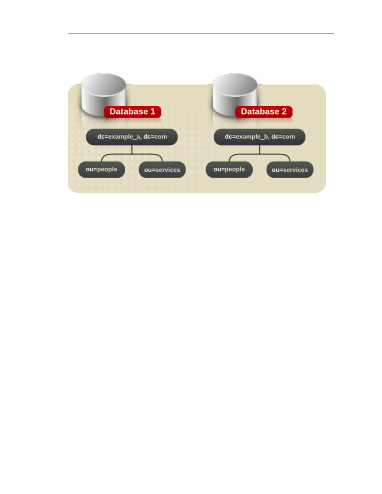
Creating the Directory Tree Structure
35
For example, create separate suffixes for example_a and example_b and store them in separate
databases.
Figure 4.1. Including Multiple Directory Trees in a Database
The databases could be stored on a single server or multiple servers depending on resource
constraints.
4.2.2. Creating the Directory Tree Structure
Decide whether to use a flat or a hierarchical tree structure. As a general rule, try to make the
directory tree as flat as possible. However, a certain amount of hierarchy can be important later when
information is partitioned across multiple databases, prepare replication, and set access controls.
The structure of the tree involves the following steps and considerations:
• Section 4.2.2.1, “Branching the Directory”
• Section 4.2.2.2, “Identifying Branch Points”
• Section 4.2.2.3, “Replication Considerations”
• Section 4.2.2.4, “Access Control Considerations”
4.2.2.1. Branching the Directory
Design the hierarchy to avoid problematic name changes. The flatter a namespace is, the less likely
the names are to change. The likelihood of a name changing is roughly proportional to the number
of components in the name that can potentially change. The more hierarchical the directory tree, the
more components in the names, and the more likely the names are to change.
Following are some guidelines for designing the directory tree hierarchy:
• Branch the tree to represent only the largest organizational subdivisions in the enterprise.
Any such branch points should be limited to divisions (Corporate Information Services, Customer
Support, Sales and Professional Services, and so forth). Make sure that the divisions used
Page 46
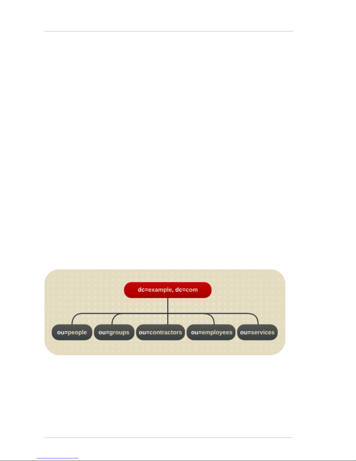
Chapter 4. Designing the Directory Tree
36
to branch the directory tree are stable; do not perform this kind of branching if the enterprise
reorganizes frequently.
• Use functional or generic names rather than actual organizational names for the branch points.
Names change, and it is really bad to have to change the directory tree every time the enterprise
renames its divisions. Instead, use generic names that represent the function of the organization (for
example, use Engineering instead of Widget Research and Development).
• If there are multiple organizations that perform similar functions, try creating a single branch point for
that function instead of branching based along divisional lines.
For example, even if there are multiple marketing organizations, each of which is responsible for a
specific product line, create a single ou=Marketing subtree. All marketing entries then belong to
that tree.
Branching in an Enterprise Environment
Name changes can be avoided if the directory tree structure is based on information that is not likely to
change. For example, base the structure on types of objects in the tree rather than organizations. This
helps avoid shuffling an entry between organizational units, which requires modifying the distinguished
name (DN), which is an expensive operation.
There are a handful of common objects that are good to use to define the structure:
• ou=people
• ou=groups
• ou=services
A directory tree organized using these objects might appear as shown below.
Figure 4.2. Example Environment Directory Tree
Branching in a Hosting Environment
For a hosting environment, create a tree that contains two entries of the object class organization
(o) and one entry of the object class organizationalUnit (ou) beneath the root suffix. For
example, Example ISP branches their directory as shown below.
Page 47
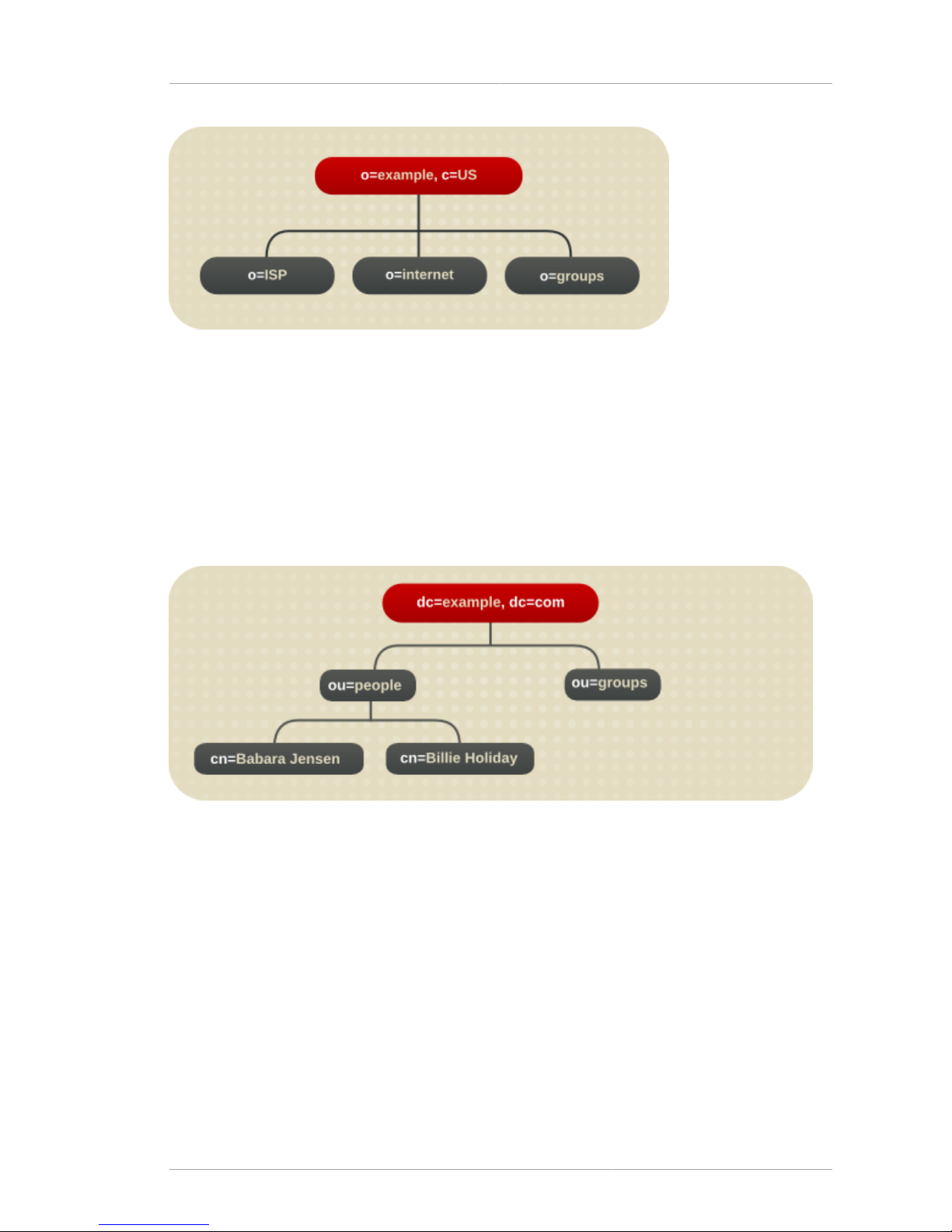
Creating the Directory Tree Structure
37
Figure 4.3. Example Hosting Directory Tree
4.2.2.2. Identifying Branch Points
When planning the branches in the directory tree, decide what attributes to use to identify the
branch points. Remember that a DN is a unique string composed of attribute-data pairs. For
example, the DN of an entry for Barbara Jensen, an employee of Example Corp., is uid=bjensen,
ou=people,dc=example,dc=com.
Each attribute-data pair represents a branch point in the directory tree. For example, the directory tree
for the enterprise "Example Corp." appears as follows:
Figure 4.4. The Directory Tree for Example Corp.
The directory tree for Example ISP, an Internet host, appears as follows:
Page 48

Chapter 4. Designing the Directory Tree
38
Figure 4.5. Directory Tree for Example ISP
Beneath the root suffix entry o=example, c=US, the tree is split into three branches. The ISP branch
contains customer data and internal information for Example ISP. The Internet branch is the domain
tree. The groups branch contains information about the administrative groups.
Consider the following when choosing attributes for the branch points:
• Be consistent.
Some LDAP client applications may be confused if the distinguished name (DN) format is
inconsistent across the directory tree. That is, if l is subordinate to ou in one part of the directory
tree, then make sure l is subordinate to ou in all other parts of the directory service.
• Try to use only the traditional attributes (shown in Section 4.2.2.2, “Identifying Branch Points”).
Using traditional attributes increases the likelihood of retaining compatibility with third-party LDAP
client applications. Using the traditional attributes also means that they are known to the default
directory schema, which makes it easier to build entries for the branch DN.
Attribute Name Definition
dc An element of the domain name, such as
dc=example; this is frequently specified
in pairs, or even longer, depending on the
domain, such as dc=example,dc=com or
dc=mtv,dc=example,dc=com.
c A country name.
o An organization name. This attribute is typically
used to represent a large divisional branching
such as a corporate division, academic discipline
(the humanities, the sciences), subsidiary, or
other major branching within the enterprise, as in
Section 4.2.1.1, “Suffix Naming Conventions”.
ou An organizational unit. This attribute is
typically used to represent a smaller divisional
branching of the enterprise than an organization.
Organizational units are generally subordinate to
the preceding organization.
Page 49
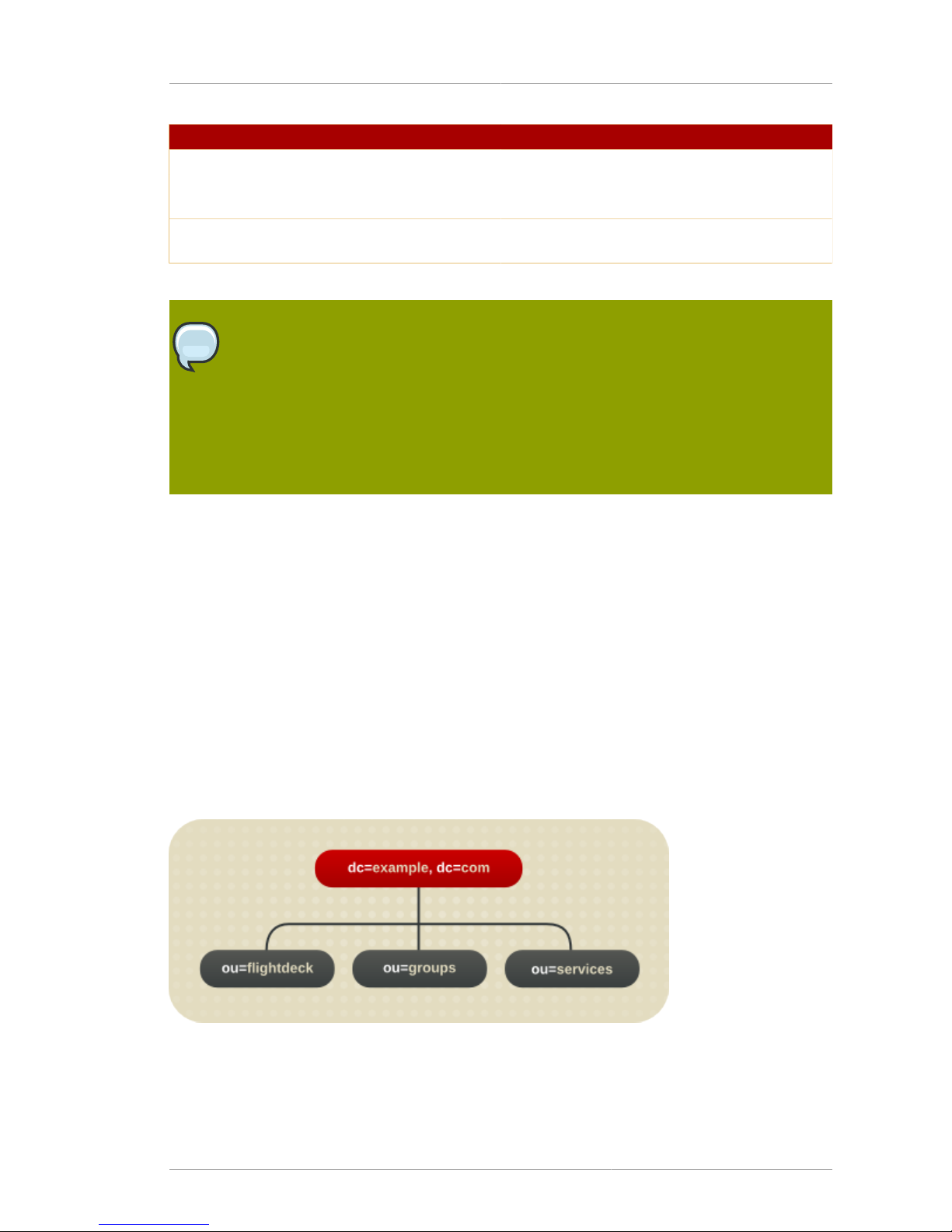
Creating the Directory Tree Structure
39
Attribute Name Definition
st A state or province name.
l or locality A locality, such as a city, country, office, or facility
name.
dc A domain component, as in Section 4.2.1.1,
“Suffix Naming Conventions”.
Table 4.1. Traditional DN Branch Point Attributes
NOTE
A common mistake is to assume that the directory is searched based on the attributes
used in the distinguished name. The distinguished name is only a unique identifier for the
directory entry and cannot be used as a search key. Instead, search for entries based
on the attribute-data pairs stored on the entry itself. Thus, if the distinguished name of
an entry is uid=bjensen, ou=People,dc=example,dc=com, then a search for
dc=example does not match that entry unless dc:example has explicitly been added as
an attribute in that entry.
4.2.2.3. Replication Considerations
During the directory tree design process, consider which entries are being replicated. A natural way to
describe a set of entries to be replicated is to specify the DN at the top of a subtree and replicate all
entries below it. This subtree also corresponds to a database, a directory partition containing a portion
of the directory data.
For example, in an enterprise environment, one method is to organize the directory tree so that it
corresponds to the network names in the enterprise. Network names tend not to change, so the
directory tree structure is stable. Further, using network names to create the top level branches of the
directory tree is useful when using replication to tie together different Directory Servers.
For instance, Example Corp. has three primary networks known as flightdeck.example.com,
tickets.example.com, and hangar.example.com. They initially branch their directory tree as
follows:
Figure 4.6. Initial Branching of the Directory Tree for Example Corp.
After creating the initial structure of the tree, they create additional branches as follows:
Page 50
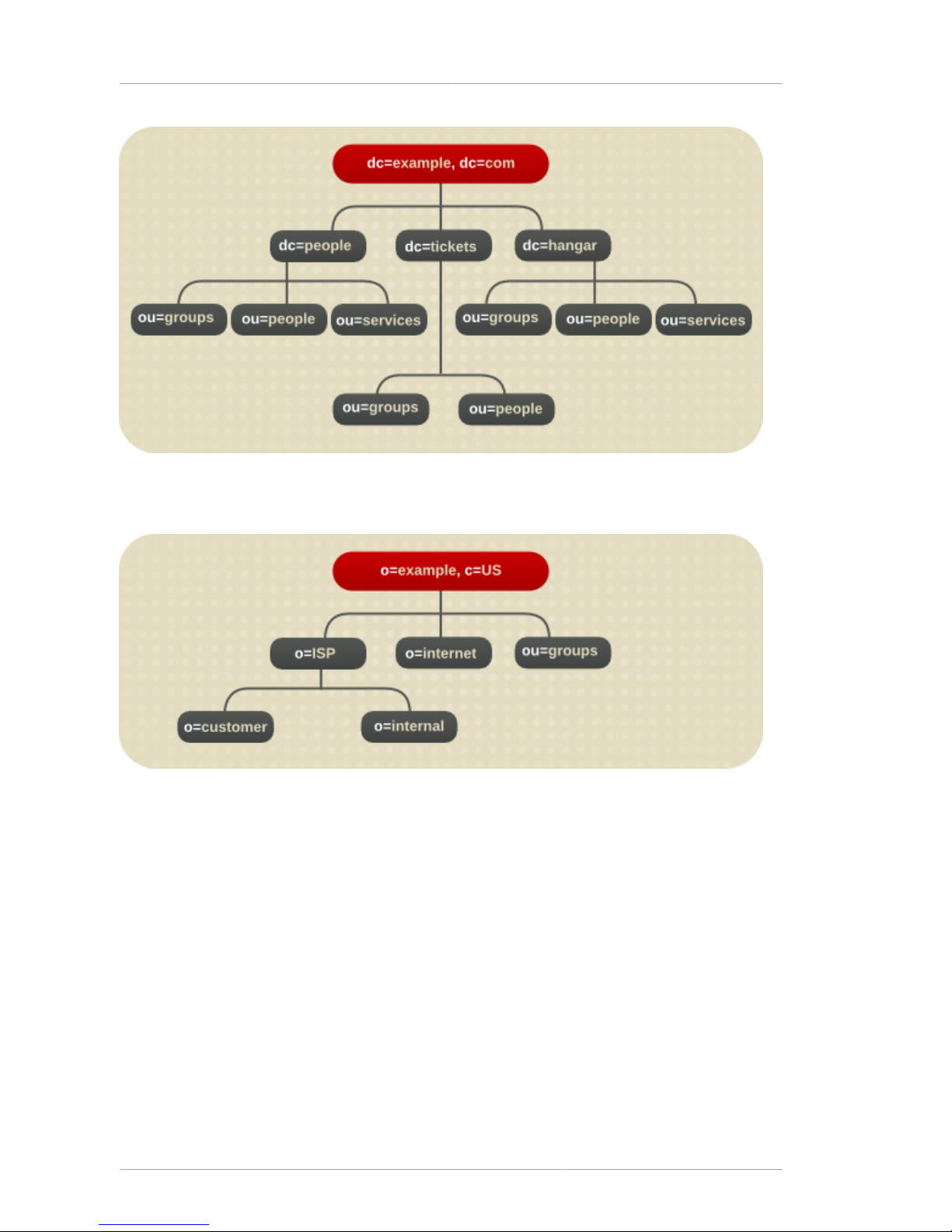
Chapter 4. Designing the Directory Tree
40
Figure 4.7. Extended Branching for Example Corp.
The Example ISP branches their directory as follows:
Figure 4.8. Directory Branching for Example ISP
After creating the initial structure of their directory tree, they create additional branches as follows:
Page 51
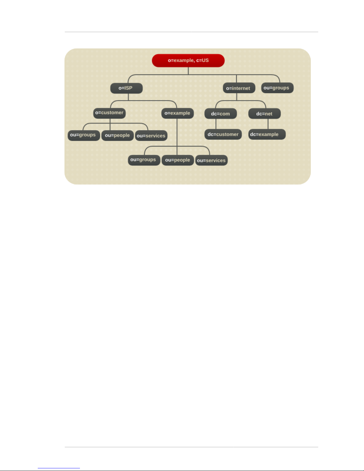
Naming Entries
41
Figure 4.9. Extended Branching for Example ISP
Both the enterprise and the hosting organization design their data hierarchies based on information
that is not likely to change often.
4.2.2.4. Access Control Considerations
Introducing a hierarchy into the directory tree can be used to enable certain types of access control.
As with replication, it is easier to group similar entries and then administer them from a single branch.
It is also possible to enable the distribution of administration through a hierarchical directory tree. For
example, to give an administrator from the marketing department access to the marketing entries
and an administrator from the sales department access to the sales entries, design the directory tree
according to those divisions.
Access controls can be based on the directory content rather than the directory tree. The filtered
mechanism can define a single access control rule stating that a directory entry has access to all
entries containing a particular attribute value. For example, set an ACI filter that gives the sales
administrator access to all the entries containing the attribute value ou=Sales.
However, ACI filters can be difficult to manage. Decide which method of access control is best suited
to the directory: organizational branching in the directory tree hierarchy, ACI filters, or a combination of
the two.
4.2.3. Naming Entries
After designing the hierarchy of the directory tree, decide which attributes to use when naming the
entries within the structure. Generally, names are created by choosing one or more of the attribute
values to form a relative distinguished name (RDN). The RDN is a single component within the
DN. This is the very first component shown, so the attribute used for that component is the naming
attribute, because it sets the unique name for the entry. The attributes to use depends on the type of
entry being named.
The entry names should adhere to the following rules:
Page 52

Chapter 4. Designing the Directory Tree
42
• The attribute selected for naming should be unlikely to change.
• The name must be unique across the directory.
A unique name ensures that a DN can refer to at most one entry in the directory.
When creating entries, define the RDN within the entry. By defining at least the RDN within the entry,
the entry can be located more easily. This is because searches are not performed against the actual
DN but rather the attribute values stored in the entry itself.
Attribute names have a meaning, so try to use the attribute name that matches the type of entry
it represents. For example, do not use l to represent an organization, or c to represent an
organizational unit.
• Section 4.2.3.1, “Naming Person Entries”
• Section 4.2.3.2, “Naming Group Entries”
• Section 4.2.3.3, “Naming Organization Entries”
• Section 4.2.3.4, “Naming Other Kinds of Entries”
4.2.3.1. Naming Person Entries
The person entry's name, the DN, must be unique. Traditionally, distinguished names use the
commonName, or cn, attribute to name their person entries. That is, an entry for a person named Babs
Jensen might have the distinguished name of cn=Babs Jensen, dc=example,dc=com.
While using the common name makes it easier to associated the person with the entry, it might not be
unique enough to exclude people with identical names. This quickly leads to a problem known as DN
name collisions, multiple entries with the same distinguished name.
Avoid common name collisions by adding a unique identifier to the common name, such as cn=Babs
Jensen+employeeNumber=23,dc=example,dc=com.
However, this can lead to awkward common names for large directories and can be difficult to
maintain.
A better method is to identify the person entries with some attribute other than cn. Consider using one
of the following attributes:
• uid
Use the uid attribute to specify some unique value of the person. Possibilities include a user login
ID or an employee number. A subscriber in a hosting environment should be identified by the uid
attribute.
•
mail
Use the mail attribute to contain the value for the person's email address. This option can lead to
awkward DNs that include duplicate attribute values (for example: mail=bjensen@example.com,
dc=example, dc=com), so use this option only if there is not some other unique value to use with
the uid attribute. For example, use the mail attribute instead of the uid attribute if the enterprise
does not assign employee numbers or user IDs for temporary or contract employees.
•
employeeNumber
Page 53

Naming Entries
43
For employees of the inetOrgPerson object class, consider using an employer assigned attribute
value such as employeeNumber.
Whatever is used for an attribute-data pair for person entry RDNs, make sure that they are unique,
permanent values. Person entry RDNs should also be readable. For example, uid=bjensen,
dc=example, dc=com is preferable to uid=b12r56A, dc=example,dc=com because
recognizable DNs simplify some directory tasks, such as changing directory entries based on their
distinguished names. Also, some directory client applications assume that the uid and cn attributes
use human-readable names.
Considerations for Person Entries in a Hosted Environment
If a person is a subscriber to a service, the entry should be of object class inetUser, and the entry
should contain the uid attribute. The attribute must be unique within a customer subtree.
If a person is part of the hosting organization, represent them as an inetOrgPerson with the
nsManagedPerson object class.
Placing Person Entries in the DIT
The following are some guidelines for placing person entries in the directory tree:
• People in an enterprise should be located in the directory tree below the organization's entry.
• Subscribers to a hosting organization need to be below the ou=people branch for the hosted
organization.
4.2.3.2. Naming Group Entries
There are four main ways to represent a group:
• A static group explicitly defines is members. The groupOfNames or groupOfUniqueNames object
classes contain values naming the members of the group. Static groups are suitable for groups
with few members, such as the group of directory administrators. Static groups are not suitable for
groups with thousands of members.
Static group entries must contain a uniqueMember attribute value because uniqueMember is
a mandatory attribute of the groupOfUniqueNames object. This object class requires the cn
attribute, which can be used to form the DN of the group entry.
Group membership is determined by the member attribute on the group entry, but group
membership for all groups is reflected in the user's entry in the memberOf attribute. The name
of every group to which a user belongs is listed as a memberOf attribute. The values of those
memberOf attributes are managed by the Directory Server.
• A dynamic group uses an entry representing the group with a search filter and subtree. Entries
matching the filter are members of the group.
• Roles unify the static and dynamic group concept. See Section 4.3, “Grouping Directory Entries” for
more information.
In a deployment containing hosted organizations, we recommend using the groupOfUniqueNames
object class to contain the values naming the members of groups used in directory administration.
Page 54

Chapter 4. Designing the Directory Tree
44
In a hosted organization, we also recommend that group entries used for directory administration be
located under the ou=Groups branch.
4.2.3.3. Naming Organization Entries
The organization entry name, like other entry names, must be unique. Using the legal name
of the organization along with other attribute values helps ensure the name is unique, such as
o=example_a+st=Washington, o=ISP,c=US.
Trademarks can also be used, but they are not guaranteed to be unique.
In a hosting environment, include the following attributes in the organization's entry:
• o
• objectClass with values of top and organization
4.2.3.4. Naming Other Kinds of Entries
The directory contains entries that represent many things, such as localities, states, countries,
devices, servers, network information, and other kinds of data.
For these types of entries, use the cn attribute in the RDN if possible. Then, for naming a group entry,
name it something like cn=administrators, dc=example,dc=com.
However, sometimes an entry's object class does not support the commonName attribute. Instead, use
an attribute that is supported by the entry's object class.
There does not have to be any correspondence between the attributes used for the entry's DN and
the attributes actually used in the entry. However, a correspondence between the DN attributes and
attributes used by the entry simplifies administration of the directory tree.
4.3. Grouping Directory Entries
After creating the required entries, group them for ease of administration. The Directory Server
supports several methods for grouping entries and sharing attributes between entries:
• Using roles
• Using class of service
The following sections describe each of these mechanisms in more detail.
4.3.1. About Roles
Roles are an entry grouping mechanism. The directory tree organizes information hierarchically. This
hierarchy is a grouping mechanism, though it is not suited for short-lived, changing organizations.
Roles provide another grouping mechanism for more temporary organizational structures.
Roles unify static and dynamic groups. Static groups create a group entry that contains a list of
members, while dynamic groups filter entries that contain a particular attribute and include them in a
single group.
Each entry assigned to a role contains the nsRole attribute, a computed attribute that specifies all of
the roles to which an entry belongs. A client application can check role membership by searching the
nsRole attribute, which is computed by the directory and is therefore always up-to-date.
Page 55

Deciding Between Roles and Groups
45
Roles are designed to be more efficient and easier to use for applications. For example, applications
can locate the roles of an entry rather than select a group and browse the members list.
Roles can organize groups in a number of different ways:
• Enumerate the members of the role.
Having an enumerated list of role members can be useful for resolving queries for group members
quickly.
• Determine whether a given entry possesses a particular role.
Knowing the roles possessed by an entry can help determine whether the entry possesses the
target role.
• Enumerate all the roles possessed by a given entry.
• Assign a particular role to a given entry.
• Remove a particular role from a given entry.
Each role has members, entries that possess the role. Members can be specified either explicitly
(meaning each entry contains an attribute associating it with a role) or dynamically (by creating a filter
that assigns entries to roles according to an attribute contained in the entry). How role membership is
specified depends on the type of role. There are three types of roles:
•
Managed roles create an explicit, enumerated list of members. Managed roles are added to entries
using the nsRoleDN attribute.
•
Filtered roles assign entries to the role depending on the attribute contained in each entry by
specifying an LDAP filter. Entries that match the filter are said to possess the role.
•
Nested roles create roles that contain other roles. The roles nested within the parent role are
specified using the nsRoleDN attribute.
4.3.2. Deciding Between Roles and Groups
Both methods of grouping entries have advantages and disadvantages. Roles reduce client-side
complexity at the cost of increased server complexity. With roles, the client application can check role
membership by searching the nsRole attribute. From the client application point of view, the method
for checking membership is uniform and is performed on the server side.
Dynamic groups, from an application point of view, offer no support from the server to provide a list
of group members. Instead, the application retrieves the group definitions and then runs the filter. For
static groups, the application must make sure the user is part of a particular UniqueMember attribute
value. The method for determining group membership is not uniform.
Managed roles can do everything that static groups can do, while filtered roles can filter and identify
members as dynamic groups do.
Even though roles are easier to use, more flexible, and reduce client complexity, they do so at the cost
of increased server complexity. Determining role membership is more resource intensive because the
server does the work for the client application.
Page 56

Chapter 4. Designing the Directory Tree
46
4.3.3. About Class of Service
A class of service (CoS) shares attributes between entries in a way that is invisible to applications.
With CoS, some attribute values may not be stored with the entry itself. Instead, they are generated by
class of service logic as the entry is sent to the client application.
For example, the directory contains thousands of entries that all share the common attribute
facsimileTelephoneNumber. Traditionally, to change the fax number required updating each entry
individually, a large job for administrators that runs the risk of not updating all entries. With CoS, the
attribute value can be generated dynamically. The facsimileTelephoneNumber attribute is stored
in one location, and each entry retrieves its fax number attribute from that location. For the application,
these attributes appear just like all other attributes, despite not actually being stored on the entries
themselves.
Each CoS is comprised of the several entries in the directory:
• The CoS definition entry identifies the type of CoS. It is stored as an LDAP subentry below the
branch it affects.
•
The template entry contains a list of the shared attribute values. Changes to the template entry
attribute values are automatically applied to all the entries sharing the attribute.
The CoS definition entry and the template entry interact to provide attribute values to their target
entries, the entries within their scope. The value they provide depends upon the following:
• The entry's DN (different portions of the directory tree might contain different CoS).
• A service class attribute value stored with the entry.
The absence of a service class attribute can imply a specific default CoS.
• The attribute value stored in the CoS template entry.
Each CoS template entry supplies the attribute value for a particular CoS.
• The object class of the entry.
CoS attribute values are generated only when an entry contains an object class allowing the
attribute when schema checking is turned on; otherwise, all attribute values are generated.
• The attribute stored in some particular entry in the directory tree.
Types of CoS
There are three different types of CoS depending on how the value of the dynamic attributes is to be
generated:
•
Pointer CoS identifies the template entry using the template DN only. There may be only one
template DN for each pointer CoS. A pointer CoS applies to all entries within the scope of the
template entry.
•
Indirect CoS identifies the template entry using the value of one of the target entry's attributes. The
target entry's attribute must contain the DN of an existing entry.
Page 57

Virtual Directory Information Tree Views
47
•
Classic CoS identifies the template entry by both its DN and the value of one of the target entry's
attributes. Classic CoS can have multiple template entries, including a default CoS template to be
applied to those entries that do not belong to any other CoS template.
Roles and the classic CoS can be used together to provide role-based attributes. These attributes
appear on an entry because it possesses a particular role with an associated CoS template. For
example, use a role-based attribute to set the server look-through limit on a role-by-role basis.
4.4. Virtual Directory Information Tree Views
Directory Server supports a concept for hierarchical navigation and organization of directory
information called virtual directory information tree views or virtual DIT views.
NOTE
Virtual views are not entirely compatible with multiple backends in that the entries to
be returned by the views must reside in the same backend; the search is limited to one
backend.
4.4.1. About Virtual DIT Views
There are two ways to configure the directory namespace:
• A hierarchical directory information tree.
• A flat directory information tree.
The hierarchical DIT is useful for navigating the directory but is cumbersome and time-consuming to
change. A major organizational change to a hierarchical DIT can be an expensive and time-consuming
operation, because it usually involves considerable service disruption. This can usually only be
minimized by performing changes after hours and during periods of low traffic.
The flat DIT, while requiring little to no change, does not provide a convenient way to navigate or
manage the entries in the directory service. A flat DIT also presents many management challenges as
administration becomes more complex without any natural hierarchical groupings.
Page 58

Chapter 4. Designing the Directory Tree
48
Figure 4.10. Examples of a Flat and an Organizationally-Based DIT
Using a hierarchical DIT, a deployment must then determine the subject domain of the hierarchy. Only
one choice can be made; the natural tendency is to choose the organizational hierarchy.
This view of the organization serves well in many cases, but having only a single view can be very
limiting for directory navigation and management. For example, an organizational hierarchy is fine
for looking for entries that belong to people in the Accounts department. However, this view is much
less useful for finding entries that belong to people in a geographical location, such as Mountain
View, California. The second query is as valid as the first, yet it requires knowledge of the attributes
contained in the entries and additional search tools. For such a case, navigation via the DIT is not an
option.
Similarly, management of the directory is much easier when the DIT matches the requirements of
the management function. The organization of the DIT may also be affected by other factors, such
as replication and migration considerations, that cause the DIT to have functional utility for those
applications but very little practical utility in other cases.
From the above discussion, it is clear that hierarchies are a useful mechanism for navigation and
management. To avoid the burden of making changes to an existing DIT, however, a deployment may
elect to forgo a hierarchy altogether in favor of a flat DIT.
It would be advantageous for deployments if the directory provided a way to create an arbitrary
number of hierarchies that get mapped to entries without having to move the target entries in question.
The virtual DIT views feature of Directory Server resolves the quandary of deciding the type of DIT to
use for the directory deployment.
Virtual DIT views provide a way to hierarchically navigate entries without the requirement that those
entries physically exist in any particular place. The virtual DIT view uses information about the entries
to place them in the view hierarchy. To client applications, virtual DIT views appear as ordinary
container hierarchies. In a sense, virtual DIT views superimpose a DIT hierarchy over a set of entries,
irrespective of whether those entries are in a flat namespace or in another hierarchy of their own.
Page 59

About Virtual DIT Views
49
Create a virtual DIT view hierarchy in the same way as a normal DIT hierarchy. Create the same
entries (for example, organizational unit entries) but with an additional object class (nsview) and
a filter attribute (nsviewfilter) that describes the view. After adding the additional attribute, the
entries that match the view filter instantly populate the view. The target entries only appear to exist in
the view; their true location never changes. Virtual DIT views behave like normal DITs in that a subtree
or a one-level search can be performed with the expected results being returned.
For information about adding and modifying entries, refer to "Creating Directory Entries" in the Red
Hat Directory Server Administrator's Guide
Figure 4.11. A Combined DIT Using Views
The DIT Figure 4.11, “A Combined DIT Using Views” in illustrates what happens when the two DITs
shown in Figure 4.10, “Examples of a Flat and an Organizationally-Based DIT” are combined using
views. Because views inherently allow entries to appear in more than one place in a view hierarchy,
this feature has been used to expand the ou=Sales entry to enable viewing the Sales entries either
by location or by product.
Given a set of virtual DIT view hierarchies, a directory user can use the view that makes the most
sense to navigate to the required entries. For example, if the target entries were those who live
in Mountain View, a view which begins by navigating using location-based information is most
appropriate. If it were an organizational question, the organization view would be a better choice. Both
of these views exist in the Directory Server at the same time and operate on the same entries; the
different views just have different objectives when displaying their version of the directory structure.
The entries in the views-enabled directory in Figure 4.11, “A Combined DIT Using Views” are
contained in a flat namespace just below the parent of the top-most view in the hierarchy. This is not
required. The entries can exist in a hierarchy of their own. The only concern that a view has about the
placement of an entry is that it must be a descendant of the parent of the view hierarchy.
Page 60
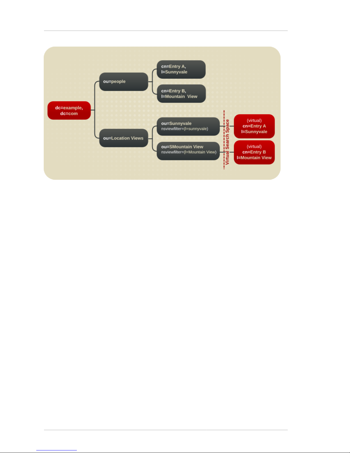
Chapter 4. Designing the Directory Tree
50
Figure 4.12. A DIT with a Virtual DIT View Hierarchy
• The sub-tree ou=People contains the real Entry A and Entry B entries.
• The sub-tree ou=Location Views is a view hierarchy.
• The leaf nodes ou=Sunnyvale and ou=Mountain View each contain an attribute,
nsviewfilter, which describes the view.
These are leaf nodes because they do not contain the real entries. However, when a client
application searches these views, it finds Entry A under ou=Sunnyvale and Entry B under
ou=Mountain View. This virtual search space is described by the nsviewfilter attributes of all
ancestor views. A search made from a view returns both entries from the virtual search space and
those from the actual search space. This enables the view hierarchies to function as a conventional
DIT or change a conventional DIT into a view hierarchy.
4.4.2. Advantages of Using Virtual DIT Views
The deployment decisions become easier with virtual DIT views because:
• Views facilitate the use of a flat namespace for entries, because virtual DIT views provide
navigational and managerial support similar to those provided by traditional hierarchies.
In addition, whenever there is a change to the DIT, the entries never need to be moved; only the
virtual DIT view hierarchies change. Because these hierarchies contain no real entries, they are
simple and quick to modify.
• Oversights during deployment planning are less catastrophic with virtual DIT views. If the hierarchy
is not developed correctly in the first instance, it can be changed easily and quickly without
disrupting the service.
• View hierarchies can be completely revised in minutes and the results instantly realized, significantly
reducing the cost of directory maintenance.
Page 61

Example of Virtual DIT Views
51
Changes to a virtual DIT hierarchy are instantly realized. When an organizational change occurs,
a new virtual DIT view can be created quickly. The new virtual DIT view can exist at the same time
as the old view, thereby facilitating a more gradual changeover for the entries themselves and for
the applications that use them. Because an organizational change in the directory is not an all-ornothing operation, it can be performed over a period of time and without service disruption.
• Using multiple virtual DIT views for navigation and management allows for more flexible use of the
directory service.
With the functionality provided by virtual DIT views, an organization can use both the old and new
methods to organize directory data without any requirement to place entries at certain points in the
DIT.
• Virtual DIT view hierarchies can be created as a kind of ready-made query to facilitate the retrieval
of commonly-required information.
• Views promote flexibility in working practices and reduce the requirement that directory users create
complex search filters, using attribute names and values that they would otherwise have no need to
know.
The flexibility of having more than one way to view and query directory information allows end users
and applications to find what they need intuitively through hierarchical navigation.
4.4.3. Example of Virtual DIT Views
The LDIF entries below show a virtual DIT view hierarchy that is based on location. Any entry that
resides below dc=example, dc=com and fits the view description appears in this view, organized by
location.
dn: ou=Location Views, dc=example,dc=com
objectclass: top
objectclass: organizationalUnit
objectclass: nsView
ou: Location Views
description: views categorized by location
dn: ou=Sunnyvale, ou=Location Views, dc=example,dc=com
objectclass: top
objectclass: organizationalUnit
objectclass: nsView
ou: Sunnyvale
nsViewFilter: (l=Sunnyvale)
description: views categorized by location
dn: ou=Santa Clara, ou=Location Views, dc=example,dc=com
objectclass: top
objectclass: organizationalUnit
objectclass: nsView
ou: Santa Clara
nsViewFilter: (l=Santa Clara)
Page 62

Chapter 4. Designing the Directory Tree
52
description: views categorized by location
dn: ou=Cupertino, ou=Location Views, dc=example,dc=com
objectclass: top
objectclass: organizationalUnit
objectclass: nsView
ou: Cupertino
nsViewFilter: (l=Cupertino)
description: views categorized by location
A subtree search based at ou=Location Views, dc=example, dc=com would return all entries
below dc=example,dc=com which match the filters (l=Sunnyvale), (l=Santa Clara), or
(l=Cupertino). Conversely, a one-level search would return no entries other than the child view
entries because all qualifying entries reside in the three descendant views.
The ou=Location Views, dc=example, dc=com view entry itself does not contain a filter.
This feature facilitates hierarchical organization without the requirement to further restrict the entries
contained in the view. Any view may omit the filter. Although the example filters are very simple, the
filter used can be as complex as necessary.
It may be desirable to limit the type of entry that the view should contain. For example, to limit this
hierarchy to contain only people entries, add an nsfilter attribute to ou=Location Views,
dc=example, dc=com with the filter value (objectclass=organizationalperson).
Each view with a filter restricts the content of all descendant views, while descendant views with
filters also restrict their ancestor's contents. For example, creating the top view ou=Location
Views first together with the new filter mentioned above would create a view with all entries with
the organization object class. When the descendant views are added that further restrict entries,
the entries that now appear in the descendant views are removed from the ancestor views. This
demonstrates how virtual DIT views mimic the behavior of traditional DITs.
Although virtual DIT views mimic the behavior of traditional DITs, views can do something that
traditional DITs cannot: entries can appear in more than one location. For example, to associate
Entry B with both Mountain View and Sunnyvale (see Figure 4.12, “A DIT with a Virtual DIT
View Hierarchy”), add the Sunnyvale value to the location attribute, and the entry appears in both
views.
4.4.4. Views and Other Directory Features
Both class of service and roles in Directory Server support views; see Section 4.3, “Grouping Directory
Entries”. When adding a class of service or a role under a view hierarchy, the entries that are both
logically and actually contained in the view are considered within scope. This means that roles and
class of service can be applied using a virtual DIT view, but the effects of that application can be seen
even when querying the flat namespace.
For information on using these features, refer to "Advanced Entry Management," in the Red Hat
Directory Server Administrator's Guide.
The use of views requires a slightly different approach to access control. Because there is currently no
explicit support for ACLs in views, create role-based ACLs at the view parent and add the roles to the
appropriate parts of the view hierarchy. In this way, take advantage of the organizational property of
the hierarchy.
Page 63

Effects of Virtual Views on Performance
53
If the base of a search is a view and the scope of the search is not a base, then the search is a viewsbased search. Otherwise, it is a conventional search.
For example, performing a search with a base of dc=example, dc=com does not return any entries
from the virtual search space are returned; in fact, no virtual-search-space search is performed. Views
processing occurs only if the search base is ou=Location Views. This way, views ensure that the
search does not result in entries from both locations. (If it were a conventional DIT, entries from both
locations are returned.)
4.4.5. Effects of Virtual Views on Performance
The performance of views-based hierarchies depends on the construction of the hierarchy itself and
the number of entries in the DIT. In general, there may be a marginal change in performance (within a
few percentage points of equivalent searches on a conventional DIT) if virtual DIT views are enabled
in the directory service. If a search does not invoke a view, then there is no performance impact. Test
the virtual DIT views against expected search patterns and loads before deployment.
We also recommend that the attributes used in view filters be indexed if the views are to be used as
general-purpose navigation tools in the organization. Further, when a sub-filter used by views matches
a configured virtual list view index, that index is used in views evaluation.
There is no need to tune any other part of the directory specifically for views.
4.4.6. Compatibility with Existing Applications
Virtual DIT views are designed to mimic conventional DITs to a high degree. The existence of views
should be transparent to most applications; there should be no indication that they are working with
views. Except for a few specialized cases, there is no need for directory users to know that views are
being used in a Directory Server instance; views appear and behave like conventional DITs.
Certain types of applications may have problems working with a views-enabled directory service. For
example:
• Applications that use the DN of a target entry to navigate up the DIT.
This type of application would find that it is navigating up the hierarchy in which the entry physically
exists instead of the view hierarchy in which the entry was found. The reason for this is that views
make no attempt to disguise the true location of an entry by changing the DN of the entry to conform
to the view's hierarchy. This is by design - many applications would not function if the true location
of an entry were disguised, such as those applications that rely on the DN to identify a unique entry.
This upward navigation by deconstructing a DN is an unusual technique for a client application, but,
nonetheless, those clients that do this may not function as intended.
• Applications that use the numSubordinates operational attribute to determine how many entries
exist beneath a node.
For the nodes in a view, this is currently a count of only those entries that exist in the real search
space, ignoring the virtual search space. Consequently, applications may not evaluate the view with
a search.
4.5. Directory Tree Design Examples
The following sections provide examples of directory trees designed to support a flat hierarchy as well
as several examples of more complex hierarchies.
Page 64

Chapter 4. Designing the Directory Tree
54
4.5.1. Directory Tree for an International Enterprise
To support an international enterprise, use the Internet domain name as the root point for the directory
tree, then branch the tree immediately below that root point for each country where the enterprise has
operations. Avoid using a country designator as the root point for the directory tree, as mentioned in
Section 4.2.1.1, “Suffix Naming Conventions”, especially if the enterprise is international.
Because LDAP places no restrictions on the order of the attributes in the DNs, the c attribute can
represent each country branch:
Figure 4.13. Using the c Attribute to Represent Different Countries
However, some administrators feel that this is stylistically awkward, so instead use the l attribute to
represent different countries:
Figure 4.14. Using the l Attribute to Represent Different Countries
4.5.2. Directory Tree for an ISP
Internet service providers (ISPs) may support multiple enterprises with their directories. ISP should
consider each of the customers as a unique enterprise and design their directory trees accordingly.
For security reasons, each account should be provided a unique directory tree with a unique suffix and
an independent security policy.
An ISP should consider assigning each customer a separate database and storing these databases
on separate servers. Placing each directory tree in its own database allows data to be backed up and
restored for each directory tree without affecting the other customers.
Page 65
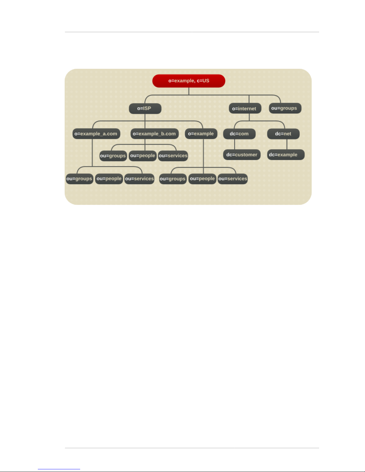
Other Directory Tree Resources
55
In addition, partitioning helps reduce performance problems caused by disk contention and reduces
the number of accounts potentially affected by a disk outage.
Figure 4.15. Directory tree for Example ISP
4.6. Other Directory Tree Resources
See the following for more information about designing the directory tree:
• RFC 2247:1 Using Domains in LDAP/X.500 Distinguished Names
• RFC 2253:2 LDAPv3, UTF-8 String Representation of Distinguished Names
Page 66

56
Page 67

Chapter 5.
57
Designing the Directory Topology
Chapter 4, Designing the Directory Tree covers how to design the directory service stores entries.
Because Red Hat Directory Server can store a large number of entries, it is possible to distribute
directory entries across more than one server. The directory's topology describes how the directory
tree is divided among multiple physical Directory Servers and how these servers link with one another.
This chapter describes planning the topology of the directory service.
5.1. Topology Overview
Directory Server can support a distributed directory, where the directory tree (designed in Chapter 4,
Designing the Directory Tree) is spread across multiple physical Directory Servers. The way the
directory is divided across those servers helps accomplish the following:
• Achieve the best possible performance for directory-enabled applications.
• Increase the availability of the directory service.
• Improve the management of the directory service.
The database is the basic unit for jobs such as replication, performing backups, and restoring data. A
single directory can be divided into manageable pieces and assigned to separate databases. These
databases can then be distributed between a number of servers, reducing the workload for each
server. More than one database can be located on a single server. For example, one server might
contain three different databases.
When the directory tree is divided across several databases, each database contains a portion of
the directory tree, called a suffix. For example, one database can be used to store only entries in the
ou=people, dc=example,dc=com suffix, or branch, of the directory tree.
When the directory is divided between several servers, each server is responsible for only a part of the
directory tree. The distributed directory service works similarly to the Domain Name Service (DNS),
which assigns each portion of the DNS namespace to a particular DNS server. Likewise, the directory
namespace can be distributed across servers while maintaining a directory service that, from a client's
point of view, appears to be a single directory tree.
The Directory Server also provides knowledge references, mechanisms for linking directory data
stored in different databases. Directory Server includes two types of knowledge references; referrals
and chaining.
The remainder of this chapter describes databases and knowledge references, explains the
differences between the two types of knowledge references, and describes how to design indexes to
improve the performance of the databases.
5.2. Distributing the Directory Data
Distributing the data allows the directory service to be scaled across multiple servers without
physically containing those directory entries on each server in the enterprise. A distributed directory
can therefore hold a much larger number of entries than would be possible with a single server.
In addition, the directory service can be configured to hide the distribution details from the user. As far
as users and applications are concerned, there is only a single directory that answers their directory
queries.
Page 68
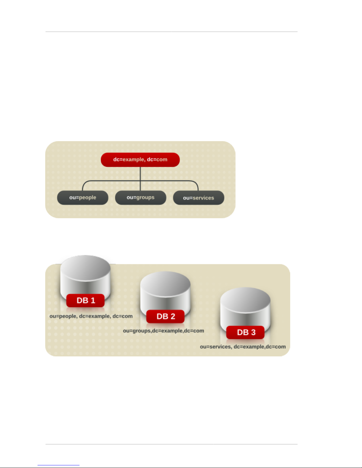
Chapter 5. Designing the Directory Topology
58
The following sections describe the mechanics of data distribution in more detail:
• Section 5.2.1, “About Using Multiple Databases”
• Section 5.2.2, “About Suffixes”
5.2.1. About Using Multiple Databases
Directory Server stores data in LDBM databases. This a high-performance, disk-based database.
Each database consists of a set of large files that contain all of the data assigned to it.
Different portions of the directory tree can be stored in different databases.
For example, Figure 5.1, “Storing Suffix Data in Separate Databases” shows three suffixes being
stored in three separate databases.
Figure 5.1. Storing Suffix Data in Separate Databases
When the directory tree is divided between a number of databases, these databases can then be
distributed across multiple servers. For example, if there are three databases, DB1, DB2, and DB3, to
contain the three suffixes of the directory tree, they can be stored on two servers, Server A and Server
B.
Page 69
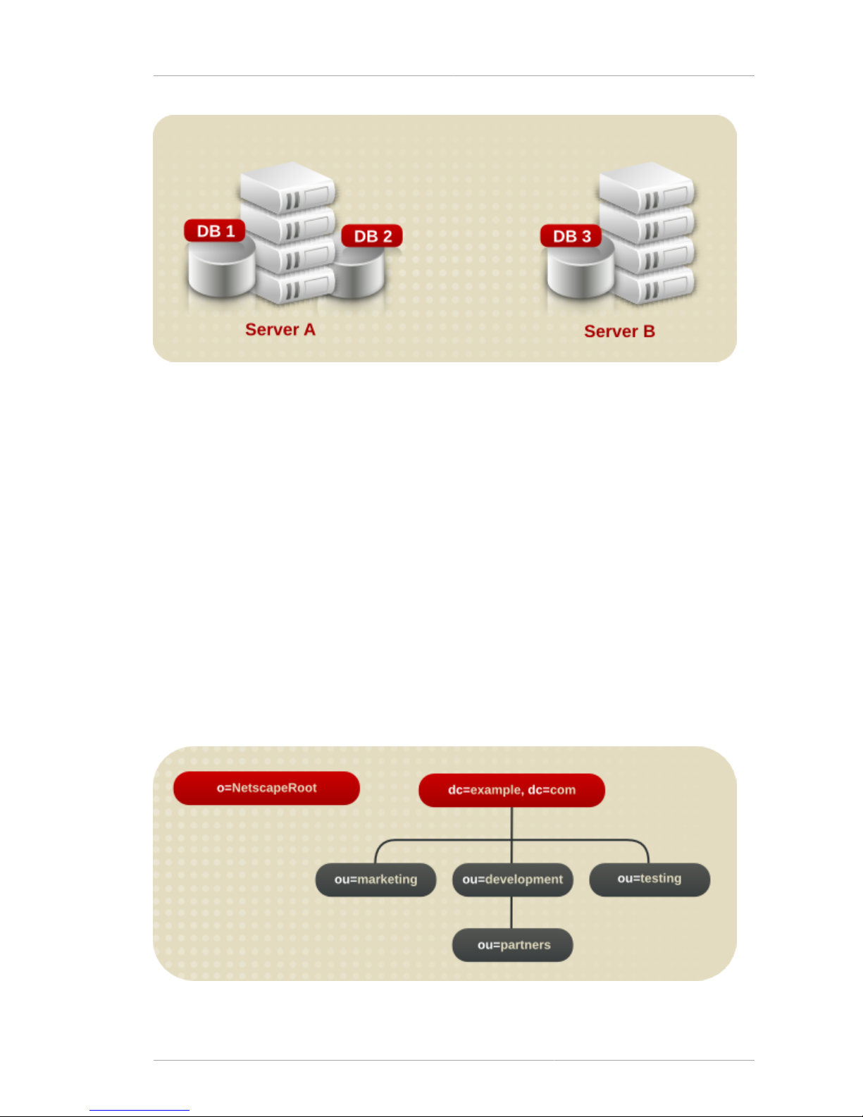
About Suffixes
59
Figure 5.2. Dividing Suffix Databases Between Separate Servers
Server A contains DB1 and DB2, and Server B contains DB3.
Distributing databases across multiple servers reduces the workload on each server. The directory
service can therefore be scaled to a much larger number of entries than would be possible with a
single server.
In addition, Directory Server supports adding databases dynamically, which means that new
databases can be added when the directory service needs them without taking the entire directory
service off-line.
5.2.2. About Suffixes
Each database contains the data within a specific suffix of the Directory Server. Both root and
subsuffixes can be created to organize the contents of the directory tree. A root suffix is the entry
at the top of a tree. It can be the root of the directory tree or part of a larger tree designed for the
Directory Server. A subsuffix is a branch beneath a root suffix. The data for root and subsuffixes are
contained by databases.
For example, Example Corp. creates suffixes to represent the distribution of their directory data.
Figure 5.3. Directory Tree for Example Corp.
Page 70

Chapter 5. Designing the Directory Topology
60
If Example Corp. decided to spread their directory tree across five different databases, the new tree
would appear as follows:
Figure 5.4. Directory Tree Spread across Multiple Databases
The resulting suffixes would contain the following entries:
Figure 5.5. Suffixes for a Distributed Directory Tree
The o=NetscapeRoot and dc=example,dc=com suffixes are both root suffixes. The
ou=testing,dc=example,dc=com suffix, the ou=development,dc=example,dc=com suffix,
and the ou=partners,ou=development,dc=example,dc=com suffix are all subsuffixes of the
dc=example,dc=com root suffix. The root suffix dc=example,dc=com contains the data in the
ou=marketing branch of the original directory tree.
Using Multiple Root Suffixes
The directory service might contain more than one root suffix. For example, an ISP called "Example"
might host several websites, one for example_a.com and one for example_b.com. The ISP would
create two root suffixes, one corresponding to the o=example_a.com naming context and one
corresponding to the o=example_b.com naming context. The directory tree would appear as follows:
Page 71

About Knowledge References
61
Figure 5.6. Directory Tree with Multiple Root Suffixes
The dc=example, dc=com entry represents a root suffix. The entry for each hosted ISP is also a
root suffix (o=example_a and o=example_b). The ou=people and the ou=groups branches are
subsuffixes under each root suffix.
5.3. About Knowledge References
After distributing the data over several databases, define the relationship between the distributed
data using knowledge references, pointers to directory information held in different databases. The
Directory Server provides the following types of knowledge references to help link the distributed data
into a single directory tree:
• Referrals — The server returns a piece of information to the client application indicating that the
client application needs to contact another server to fulfill the request.
• Chaining — The server contacts other servers on behalf of the client application and returns the
combined results to the client application when the operation is finished.
The following sections describe and compare these two types of knowledge references in more detail.
5.3.1. Using Referrals
A referral is a piece of information returned by a server that informs a client application which server
to contact to proceed with an operation request. This redirection mechanism occurs when a client
application requests a directory entry that does not exist on the local server.
Directory Server supports two types of referrals:
• Default referrals — The directory returns a default referral when a client application presents a DN
for which the server does not have a matching suffix. Default referrals are stored in the configuration
file of the server. One default referral can be set for the Directory Server and a separate default
referral for each database.
Page 72

Chapter 5. Designing the Directory Topology
62
The default referral for each database is done through the suffix configuration information. When the
suffix of the database is disabled, configure the directory service to return a default referral to client
requests made to that suffix.
For more information about suffixes, refer to Section 5.2.2, “About Suffixes”. For information on
configuring suffixes, refer to the Red Hat Directory Server Administrator's Guide .
• Smart referrals — Smart referrals are stored on entries within the directory service itself. Smart
referrals point to Directory Servers that have knowledge of the subtree whose DN matches the DN
of the entry containing the smart referral.
All referrals are returned in the format of an LDAP uniform resource locator, or LDAP URL. The
following sections describe the structure of an LDAP referral, and then describe the two referral types
supported by Directory Server.
5.3.1.1. The Structure of an LDAP Referral
An LDAP referral contains information in the format of an LDAP URL. An LDAP URL contains the
following information:
• The hostname of the server to contact.
• The port number on the server that is configured to listen for LDAP requests.
• The base DN (for search operations) or target DN (for add, delete, and modify operations).
For example, a client application searches dc=example,dc=com for entries with a surname value of
Jensen. A referral returns the following LDAP URL to the client application:
ldap://europe.example.com:389/ou=people, l=europe,dc=example,dc=com
This referral instructs the client application to contact the host europe.example.com on port 389
and submit a search using the root suffix ou=people, l=europe,dc=example,dc=com.
The LDAP client application determines how a referral is handled. Some client applications
automatically retry the operation on the server to which they have been referred. Other client
applications return the referral information to the user. Most LDAP client applications provided by Red
Hat Directory Server (such as the command-line utilities) automatically follow the referral. The same
bind credentials supplied on the initial directory request are used to access the server.
Most client applications follow a limited number of referrals, or hops. The limit on the number of
referrals that are followed reduces the time a client application spends trying to complete a directory
lookup request and helps eliminate hung processes caused by circular referral patterns.
5.3.1.2. About Default Referrals
Default referrals are returned to clients when the server or database that was contacted does not
contain the requested data.
Directory Server determines whether a default referral should be returned by comparing the DN of the
requested directory object against the directory suffixes supported by the local server. If the DN does
not match the supported suffixes, the Directory Server returns a default referral.
Page 73

Using Referrals
63
For example, a directory client requests the following directory entry: uid=bjensen,
ou=people,dc=example,dc=com
However, the server only manages entries stored under the dc=europe,dc=example,dc=com
suffix. The directory returns a referral to the client that indicates which server to contact for entries
stored under the dc=example,dc=com suffix. The client then contacts the appropriate server and
resubmits the original request.
Configure the default referral to point to a Directory Server that has more information about the
distribution of the directory service. Default referrals for the server are set by the nsslapd-referral
attribute. Default referrals for each database in the directory installation are set by the nsslapd-
referral attribute in the database entry in the configuration. These attribute values are stored in the
dse.ldif file.
For information on configuring default referrals, refer to the Red Hat Directory Server Administrator's
Guide.
5.3.1.3. Smart Referrals
The Directory Server can also use smart referrals. Smart referrals associate a directory entry or
directory tree to a specific LDAP URL. This means that requests can be forwarded to any of the
following:
• The same namespace contained on a different server.
• Different namespaces on a local server.
• Different namespaces on the same server.
Unlike default referrals, smart referrals are stored within the directory service itself. For information on
configuring and managing smart referrals, refer to the Red Hat Directory Server Administrator's Guide.
For example, the directory service for the American office of the Example Corp. contains the
ou=people,dc=example,dc=com directory branch point.
Redirect all requests on this branch to the ou=people branch of the European office of Example
Corp. by specifying a smart referral on the ou=people entry itself. The smart referral is ldap://
europe.example.com:389/ou=people,dc=example,dc=com.
Any requests made to the people branch of the American directory service are redirected to the
European directory. This is illustrated below:
Page 74

Chapter 5. Designing the Directory Topology
64
Figure 5.7. Using Smart Referrals to Redirect Requests
The same mechanism can be used to redirect queries to a different server that uses a different
namespace. For example, an employee working in the Italian office of Example Corp. makes a
request to the European directory service for the phone number of an Example Corp. employee in
America. The directory service returns the referral ldap://europe.example.com:389/ou=US
employees,dc=example,dc=com.
Page 75

Using Referrals
65
Figure 5.8. Redirecting a Query to a Different Server and Namespace
Finally, if multiple suffixes are served on the same server, queries can be redirected from one
namespace to another namespace served on the same machine. For example, to redirect all queries
on the local machine for o=example,c=us to dc=example,dc=com, then put the smart referral
ldap:///dc=example, dc=com on the o=example,c=us entry.
Figure 5.9. Redirecting a Query from One Namespace to Another Namespace on the Same Server
NOTE
The third slash in this LDAP URL indicates that the URL points to the same Directory
Server.
Page 76
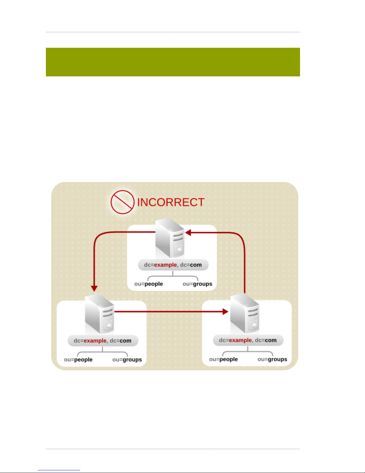
Chapter 5. Designing the Directory Topology
66
Creating a referral from one namespace to another works only for clients whose searches
are based at that distinguished name. Other kinds of operations, such as searches below
ou=people,o=example,c=US, are not performed correctly.
For more information on LDAP URLS and on how to include smart URLs on Directory Server entries,
refer to the Red Hat Directory Server Administrator's Guide.
5.3.1.4. Tips for Designing Smart Referrals
Even though smart referrals are easy to implement, consider the following points before using them:
• Keep the design simple.
Deploying the directory service using a complex web of referrals makes administration difficult.
Overusing smart referrals can also lead to circular referral patterns. For example, a referral points to
an LDAP URL, which in turn points to another LDAP URL, and so on until a referral somewhere in
the chain points back to the original server. This is illustrated below:
Figure 5.10. A Circular Referral Pattern
• Redirect at major branchpoints.
Limit referral usage to handle redirection at the suffix level of the directory tree. Smart referrals
redirect lookup requests for leaf (non-branch) entries to different servers and DNs. As a result, it is
tempting to use smart referrals as an aliasing mechanism, leading to a complex and difficult method
Page 77

Using Chaining
67
to secure directory structure. Limiting referrals to the suffix or major branch points of the directory
tree limits the number of referrals that have to be managed, subsequently reducing the directory's
administrative overhead.
• Consider the security implications.
Access control does not cross referral boundaries. Even if the server where the request originated
allows access to an entry, when a smart referral sends a client request to another server, the client
application may not be allowed access.
In addition, the client's credentials need to be available on the server to which the client is referred
for client authentication to occur.
5.3.2. Using Chaining
Chaining is a method for relaying requests to another server. This method is implemented through
database links. A database link, as described in Section 5.2, “Distributing the Directory Data”, contains
no data. Instead, it redirects client application requests to remote servers that contain the data.
During the chaining process, a server receives a request from a client application for data that the
server does not contain. Using the database link, the server then contacts other servers on behalf of
the client application and returns the results to the client application.
Each database link is associated with a remote server holding data. Configure alternate remote
servers containing replicas of the data for the database link to use in the event of a failure. For more
information on configuring database links, refer to the Red Hat Directory Server Administrator's Guide.
Database links provide the following features:
• Invisible access to remote data.
Because the database link resolves client requests, data distribution is completely hidden from the
client.
• Dynamic management.
A part of the directory service can be added or removed from the system while the entire system
remains available to client applications. The database link can temporarily return referrals to the
application until entries have been redistributed across the directory service.
This can also be implemented through the suffix itself, which can return a referral rather than
forwarding a client application to the database.
Page 78

Chapter 5. Designing the Directory Topology
68
• Access control.
The database link impersonates the client application, providing the appropriate authorization
identity to the remote server. User impersonation can be disabled on the remote servers when
access control evaluation is not required. For more information on configuring database links, refer
to the Red Hat Directory Server Administrator's Guide.
5.3.3. Deciding Between Referrals and Chaining
Both methods of linking the directory partitions have advantages and disadvantages. The method, or
combination of methods, to use depends upon the specific needs of the directory service.
The major difference between the two knowledge references is the location of the intelligence that
knows how to locate the distributed information. In a chained system, the intelligence is implemented
in the servers. In a system that uses referrals, the intelligence is implemented in the client application.
While chaining reduces client complexity, it does so at the cost of increased server complexity.
Chained servers must work with remote servers and send the results to directory clients.
With referrals, the client must handle locating the referral and collating search results. However,
referrals offer more flexibility for the writers of client applications and allow developers to provide better
feedback to users about the progress of a distributed directory operation.
The following sections describe some of the more specific differences between referrals and chaining
in greater detail.
5.3.3.1. Usage Differences
Some client applications do not support referrals. Chaining allows client applications to communicate
with a single server and still access the data stored on many servers. Sometimes referrals do not work
when a company's network uses proxies. For example, a client application may have permissions to
communicate with only one server inside a firewall. If that application is referred to a different server, it
is not able to contact it successfully.
A client must also be able to authenticate correctly when using referrals, which means that the servers
to which clients are being referred need to contain the client's credentials. With chaining, client
authentication takes place only once. Clients do not need to authenticate again on the servers to
which their requests are chained.
5.3.3.2. Evaluating Access Controls
Chaining evaluates access controls differently from referrals. With referrals, an entry for the client must
exist on all of the target servers. With chaining, the client entry does not need to be on all of the target
servers.
Performing Search Requests Using Referrals
The following diagram illustrates a client request to a server using referrals:
Page 79

Deciding Between Referrals and Chaining
69
Figure 5.11. Sending a Client Request to a Server Using Referrals
In the illustration above, the client application performs the following steps:
1. The client application first binds with Server A.
2. Server A contains an entry for the client that provides a user name and password, so it returns
a bind acceptance message. In order for the referral to work, the client entry must be present on
server A.
3. The client application sends the operation request to Server A.
4. However, Server A does not contain the requested information. Instead, Server A returns a referral
to the client application instructing it to contact Server B.
5. The client application then sends a bind request to Server B. To bind successfully, Server B must
also contain an entry for the client application.
6. The bind is successful, and the client application can now resubmit its search operation to Server
B.
This approach requires Server B to have a replicated copy of the client's entry from Server A.
Performing Search Requests Using Chaining
The problem of replicating client entries across servers is resolved using chaining. On a chained
system, the search request would occur as follows:
Page 80
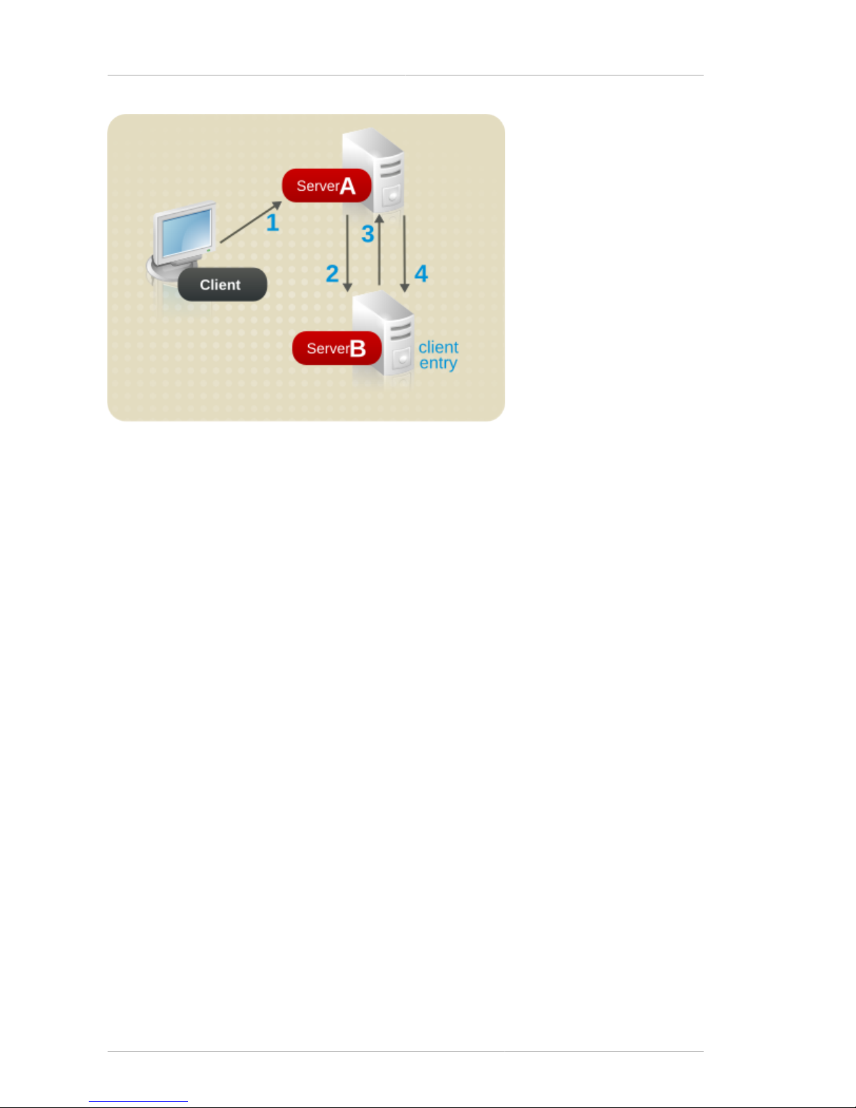
Chapter 5. Designing the Directory Topology
70
Figure 5.12. Sending a Client Request to a Server Using Chaining
In the illustration above, the following steps are performed:
1. The client application binds with Server A, and Server A tries to confirm that the user name and
password are correct.
2. Server A does not contain an entry corresponding to the client application. Instead, it contains
a database link to Server B, which contains the actual entry of the client. Server A sends a bind
request to Server B.
3. Server B sends an acceptance response to Server A.
4. Server A then processes the client application's request using the database link. The database link
contacts a remote data store located on Server B to process the search operation.
In a chained system, the entry corresponding to the client application does not need to be located on
the same server as the data the client requests. For example, a system could be set up as follows:
Page 81

Using Indexes to Improve Database Performance
71
Figure 5.13. Authenticating a Client and Retrieving Data Using Different Servers
In this illustration, the following steps are performed:
1. The client application binds with Server A, and Server A tries to confirm that the user name and
password are correct.
2. Server A does not contain an entry corresponding to the client application. Instead, it contains
a database link to Server B, which contains the actual entry of the client. Server A sends a bind
request to Server B.
3. Server B sends an acceptance response to Server A.
4. Server A then processes the client application's request using another database link. The
database link contacts a remote data store located on Server C to process the search operation.
Unsupported Access Controls
Database links do not support the following access controls:
• Controls that must access the content of the user entry are not supported when the user entry is
located on a different server. This includes access controls based on groups, filters, and roles.
• Controls based on client IP addresses or DNS domains may be denied. This is because the
database link impersonates the client when it contacts remote servers. If the remote database
contains IP-based access controls, it evaluates them using the database link's domain rather than
the original client domain.
5.4. Using Indexes to Improve Database Performance
Searches performed by client applications can be time and resource intensive, depending on the size
of the databases. To help alleviate this problem, use indexes to improve search performance.
Indexes are files stored in the directory databases. Separate index files are maintained for each
database in the directory service. Each file is named according to the attribute it indexes. The index
Page 82

Chapter 5. Designing the Directory Topology
72
file for a particular attribute can contain multiple types of indexes, so several types of index can be
maintained for each attribute. For example, a file called cn.db4 contains all of the indexes for the
common name attribute.
Different types of indexes are used depending on the types of applications that use the directory
service. Different applications may frequently search for a particular attribute, or may search the
directory in a different language, or may require data in a particular format.
5.4.1. Overview of Directory Index Types
Directory Server supports the following types of index:
•
Presence index — Lists entries that possess a particular attribute, such as uid.
•
Equality index — Lists entries that contain a specific attribute value, such as cn=Babs Jensen.
•
Approximate index — Allows approximate (or "sounds-like") searches. For example, an entry might
contain the attribute value of cn=Babs L. Jensen. An approximate search would return this value
for searches against cn~=Babs Jensen, cn~=Babs, and cn~=Jensen.
NOTE
Approximate indexes require that names be written in English using ASCII characters.
•
Substring index — Allows searches against substrings within entries. For example, a search for
cn=*derson would match common names containing this string (such as Bill Anderson, Norma
Henderson, and Steve Sanderson).
•
International index — Improves the performance of searches for information in international
directories. Configure the index to apply a matching rule by associating a locale (internationalization
OID) with the attribute being indexed.
•
Browsing index or virtual list view (VLV) index — Improves the display performance of entries in the
Directory Server Console. A browsing index can be created on any branch in the directory tree to
improve the display performance.
5.4.2. Evaluating the Costs of Indexing
Indexes improve search performance in the directory databases, but there is a cost involved:
• Indexes increase the time it takes to modify entries.
The more indexes being maintained, the longer it takes the directory service to update the database.
• Index files use disk space.
The more attributes being indexed, the more files are created. If there are approximate and
substring indexes for attributes that contain long strings, these files can grow rapidly.
• Index files use memory.
Page 83

Evaluating the Costs of Indexing
73
To run more efficiently, the directory service places as many index files in memory as possible. Index
files use memory out of the pool available depending upon the database cache size. A large number
of index files requires a larger database cache.
• Index files take time to create.
Although index files save time during searches, maintaining unnecessary indexes can waste time.
Be certain to maintain only the files needed by the client applications using the directory service.
Page 84

74
Page 85

Chapter 6.
75
Designing the Replication Process
Replicating the directory contents increases the availability and performance of the directory service.
Chapter 4, Designing the Directory Tree and Chapter 5, Designing the Directory Topology cover
the design of the directory tree and the directory topology. This chapter addresses the physical
and geographical location of the data and, specifically, how to use replication to ensure the data is
available when and where it is needed.
This chapter discusses uses for replication and offers advice on designing a replication strategy for the
directory environment.
6.1. Introduction to Replication
Replication is the mechanism that automatically copies directory data from one Red Hat Directory
Server to another. Using replication, any directory tree or subtree (stored in its own database) can
be copied between servers. The Directory Server that holds the master copy of the information
automatically copies any updates to all replicas.
Replication provides a high-availability directory service and can distribute the data geographically. In
practical terms, replication provides the following benefits:
• Fault tolerance and failover — By replicating directory trees to multiple servers, the directory service
is available even if hardware, software, or network problems prevent the directory client applications
from accessing a particular Directory Server. Clients are referred to another Directory Server for
read and write operations.
NOTE
Write failover is only possible with multi-master replication.
• Load balancing — Replicating the directory tree across servers reduces the access load on any
given machine, thereby improving server response time.
• Higher performance and reduced response times — Replicating directory entries to a location close
to users significantly improves directory response times.
• Local data management — Replication allows information to be owned and managed locally while
sharing it with other Directory Servers across the enterprise.
6.1.1. Replication Concepts
Always start planning replication by making the following fundamental decisions:
• What information to replicate.
• Which servers hold the master copy, or read-write replica, of that information.
• Which servers hold the read-only copy, or read-only replica, of that information.
• What should happen when a read-only replica receives an update request; that is, to which server it
should refer the request.
Page 86

Chapter 6. Designing the Replication Process
76
These decisions cannot be made effectively without an understanding of how the Directory Server
handles these concepts. For example, decide what information to replicate, be aware of the smallest
replication unit that the Directory Server can handle. The replication concepts used by the Directory
Server provide a framework for thinking about the global decisions that need to be made.
6.1.1.1. Unit of Replication
The smallest unit of replication is a database. An entire database can be replicated but not a subtree
within a database. Therefore, when defining the directory tree, always consider replication. For more
information on how to set up the directory tree, see Chapter 4, Designing the Directory Tree.
The replication mechanism also requires that one database correspond to one suffix. A suffix (or
namespace) that is distributed over two or more databases cannot be replicated.
6.1.1.2. Read-Write and Read-Only Replicas
A database that participates in replication is defined as a replica. Directory Server supports two
types of replicas: read-write and read-only. The read-write replicas contain master copies of directory
information and can be updated. Read-only replicas refer all update operations to read-write replicas.
6.1.1.3. Suppliers and Consumers
A server that stores a replica that is copied to a different server is called a supplier. A server that
stores a replica that is copied from a different server is called a consumer. Generally speaking, the
replica on the supplier server is a read-write replica; the replica on the consumer server is a read-only
replica. However, the following exceptions apply:
• In the case of cascading replication, the hub supplier holds a read-only replica that it supplies to
consumers. For more information, see Section 6.2.3, “Cascading Replication”.
• In the case of multi-master replication, the suppliers function as both suppliers and consumers for
the same read-write replica. For more information, see Section 6.2.2, “Multi-Master Replication”.
NOTE
In the current version of Red Hat Directory Server, replication is always initiated by the
supplier server, never by the consumer. This is unlike earlier versions of Directory Server,
which allowed consumer-initiated replication (where consumer servers could retrieve data
from a supplier server).
Suppliers
For any particular replica, the supplier server must:
• Respond to read requests and update requests from directory clients.
• Maintain state information and a changelog for the replica.
• Initiate replication to consumer servers.
The supplier server is always responsible for recording the changes made to the read-write replicas
that it manages, so the supplier server makes sure that any changes are replicated to consumer
servers.
Page 87

Replication Concepts
77
Consumers
A consumer server must:
• Respond to read requests.
• Refer update requests to a supplier server for the replica.
Whenever a consumer server receives a request to add, delete, or change an entry, the request is
referred to a supplier for the replica. The supplier server performs the request, then replicates the
change.
Hub Suppliers
In the special case of cascading replication, the hub supplier must:
• Respond to read requests.
• Refer update requests to a supplier server for the replica.
• Initiate replication to consumer servers.
For more information on cascading replication, see Section 6.2.3, “Cascading Replication”.
6.1.1.4. Replication and Changelogs
Every supplier server maintains a changelog. A changelog is a record of the modifications that have
occurred on a replica. The supplier server then replays these modifications on the replicas stored on
consumer servers, or on other suppliers in the case of multi-master replication.
When an entry is modified, a change record describing the LDAP operation that was performed is
recorded in the changelog.
The changelog size is maintained with two attributes, nsslapd-changelogmaxage or nsslapd-
changelogmaxentries. These attributes trim the old changelogs to keep the changelog size
reasonable.
6.1.1.5. Replication Agreement
Directory Servers use replication agreements to define replication. A replication agreement describes
replication between a single supplier and a single consumer. The agreement is configured on the
supplier server. It identifies:
• The database to replicate.
• The consumer server to which the data is pushed.
• The times that replication can occur.
• The DN that the supplier server must use to bind (called the supplier bind DN).
• How the connection is secured (TLS/SSL, Start TLS, client authentication, SASL, or simple
authentication).
• Any attributes that will not be replicated (see Section 6.3.2, “Replicated Selected Attributes with
Fractional Replication”).
Page 88

Chapter 6. Designing the Replication Process
78
6.1.2. Data Consistency
Consistency refers to how closely the contents of replicated databases match each other at a
given point in time. Part of the configuration for replication between servers is to schedule updates.
The supplier server always determines when consumer servers need to be updated and initiates
replication.
Directory Server offers the option of keeping replicas always synchronized or of scheduling updates
for a particular time of day or day in the week.
The advantage of keeping replicas constantly synchronized is that it provides better data consistency.
The cost is the network traffic resulting from the frequent update operations. This solution is the best
option when:
• There is a reliable, high-speed connection between servers.
• The client requests serviced by the directory service are mainly search, read, and compare
operations, with relatively few update operations.
If it is all right to a lower level of data consistency, choose the frequency of updates that best suits the
use patterns of the network or lowers the affect on network traffic. There are several situations where
having scheduled updates instead of constant updates is the best solution:
• There are unreliable or intermittently available network connections.
• The client requests serviced by the directory service are mainly update operations.
• Communication costs have to be lowered.
In the case of multi-master replication, the replicas on each supplier are said to be loosely consistent,
because at any given time, there can be differences in the data stored on each supplier. This is true,
even if the replicas are constantly synchronized, for two reasons:
• There is a latency in the propagation of update operations between suppliers.
• The supplier that serviced the update operation does not wait for the second supplier to validate it
before returning an "operation successful" message to the client.
6.2. Common Replication Scenarios
Decide how the updates flow from server to server and how the servers interact when propagating
updates. There are the four basic scenarios and a few strategies for deciding the method appropriate
for the environment. These basic scenarios can be combined to build the replication topology that best
suits the network environment.
• Section 6.2.1, “Single-Master Replication”
• Section 6.2.2, “Multi-Master Replication”
• Section 6.2.3, “Cascading Replication”
• Section 6.2.4, “Mixed Environments”
Page 89
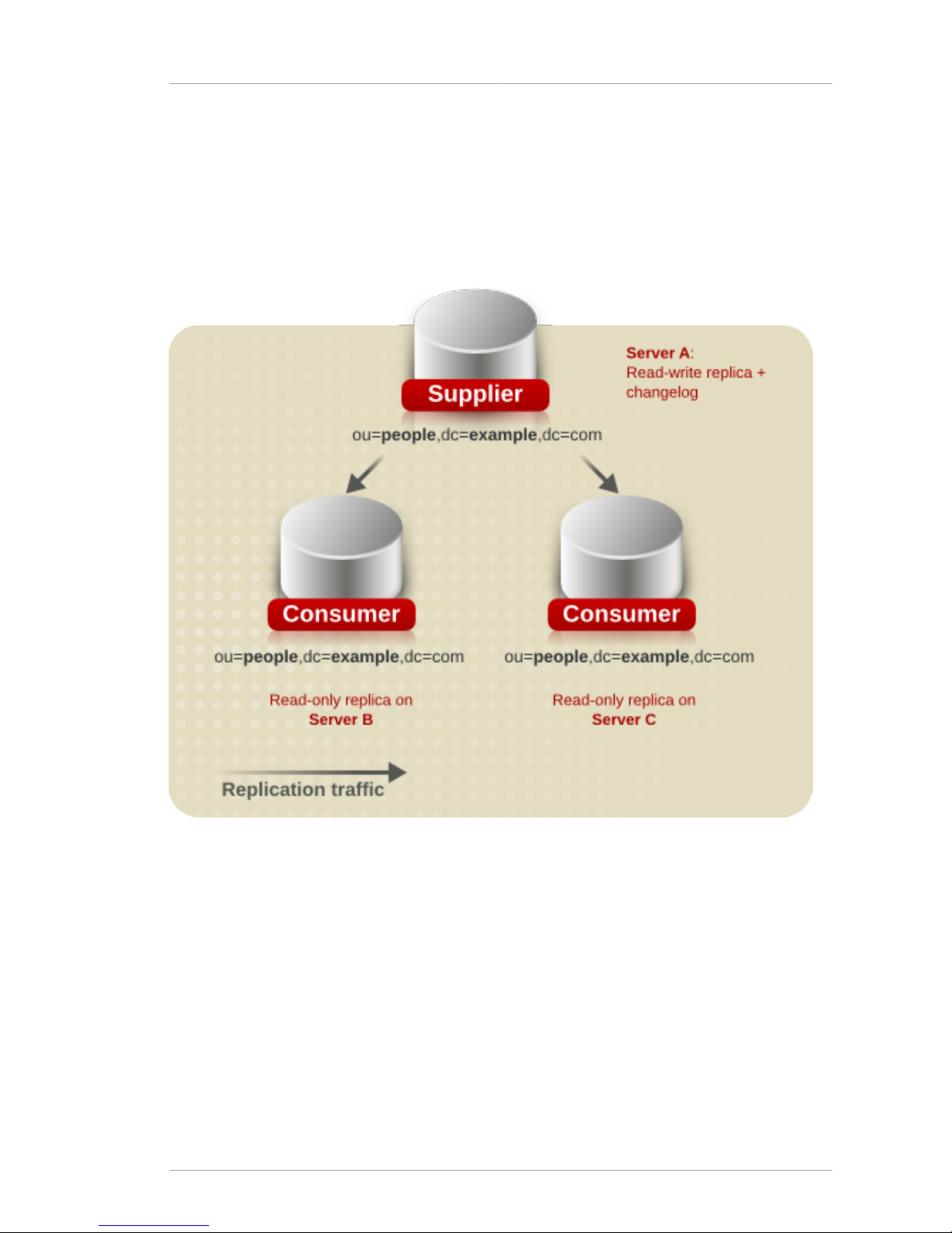
Single-Master Replication
79
6.2.1. Single-Master Replication
In the most basic replication configuration, a supplier server copies a replica directly to one or more
consumer servers. In this configuration, all directory modifications occur on the read-write replica on
the supplier server, and the consumer servers contain read-only replicas of the data.
The supplier server must perform all modifications to the read-write replicas stored on the consumer
servers. This is illustrated below.
Figure 6.1. Single-Master Replication
The supplier server can replicate a read-write replica to several consumer servers. The total number
of consumer servers that a single supplier server can manage depends on the speed of the networks
and the total number of entries that are modified on a daily basis. However, a supplier server is
capable of maintaining several consumer servers.
6.2.2. Multi-Master Replication
In a multi-master replication environment, master copies of the same information can exist on multiple
servers. This means that data can be updated simultaneously in different locations. The changes that
occur on each server are replicated to the other servers. This means that each server functions as
both a supplier and a consumer.
Page 90

Chapter 6. Designing the Replication Process
80
When the same data is modified on multiple servers, there is a conflict resolution procedure to
determine which change is kept. The Directory Server considers the valid change to be the most
recent one.
Multiple servers can have master copies of the same data, but, within the scope of a single replication
agreement, there is only one supplier server and one consumer. Consequently, to create a multimaster environment between two supplier servers that share responsibility for the same data, create
more than one replication agreement.
Figure 6.2. Multi-Master Replication Configuration (Two Suppliers)
In the above illustration, supplier A and supplier B each hold a read-write replica of the same data.
To create a multi-master environment between four supplier servers that share responsibility for the
same data, create a range of replication agreements. Keep in mind that the four suppliers can be
configured in different topologies and that there are many variables that have a direct impact on the
topology selection.
Figure 6.3, “Multi-Master Replication Configuration A (Four Suppliers)” illustrates a fully connected
mesh topology where all four supplier servers feed data to the other three supplier servers (which
also function as consumers). A total of twelve replication agreements exist between the four supplier
servers. This topology provides high server failure tolerance at the expense of high data dispersal for
every supplier.
Page 91

Multi-Master Replication
81
Figure 6.3. Multi-Master Replication Configuration A (Four Suppliers)
Figure 6.4, “Multi-Master Replication Configuration B (Four Suppliers)” illustrates a topology where
each supplier server feeds data to two other supplier servers (which also function as consumers).
Only eight replication agreements exist between the four supplier servers, compared to the twelve
agreements shown for the topology in Figure 6.3, “Multi-Master Replication Configuration A (Four
Suppliers)”. This topology is beneficial where the possibility of two or more servers failing at the same
time is negligible. Because each supplier only supplies two other servers, such a configuration is
useful in reducing the network traffic and reducing server load.
Page 92
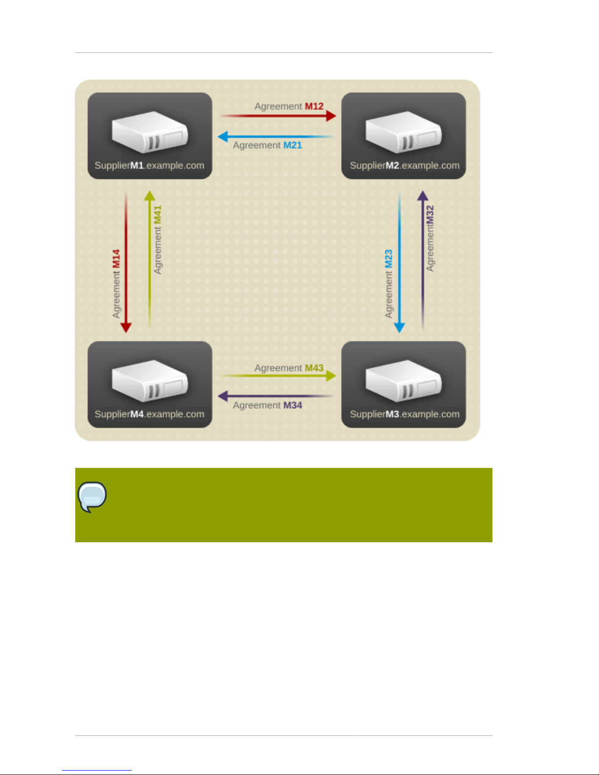
Chapter 6. Designing the Replication Process
82
Figure 6.4. Multi-Master Replication Configuration B (Four Suppliers)
NOTE
Red Hat Directory Server supports a maximum of four supplier servers in any replication
environment. However, the number of consumer servers that hold the read-only replicas is
unlimited.
The following diagram illustrates the replication traffic in an environment with two suppliers (read-write
replicas in the illustration), and two consumers (read-only replicas in the illustration). This figure shows
that the consumers can be updated by both suppliers. The supplier servers ensure that the changes
do not collide.
Page 93

Cascading Replication
83
Figure 6.5. Replication Traffic in a Multi-Master Environment
6.2.3. Cascading Replication
In a cascading replication scenario, a hub supplier receives updates from a supplier server and
replays those updates on consumer servers. The hub supplier is a hybrid; it holds a read-only replica,
like a typical consumer server, and it also maintains a changelog like a typical supplier server.
Hub suppliers forward master data as they receive it from the original suppliers. Similarly, when a hub
supplier receives an update request from a directory client, it refers the client to the supplier server.
Cascading replication is useful if some of the network connections between various locations
in the organization are better than others. For example, Example Corp. keeps the master copy
of its directory data in Minneapolis, and the consumer servers in New York and Chicago. The
network connection between Minneapolis and New York is very good, but the connection between
Minneapolis and Chicago is poor. Since the network between New York and Chicago is fair, Example
administrators use cascading replication to move directory data from Minneapolis to New York to
Chicago.
Page 94

Chapter 6. Designing the Replication Process
84
Figure 6.6. Cascading Replication Scenario
Figure 6.7, “Replication Traffic and Changelogs in Cascading Replication” illustrates the same
scenario from a different perspective, which shows how the replicas are configured on each server
(read-write or read-only), and which servers maintain a changelog.
Page 95

Mixed Environments
85
Figure 6.7. Replication Traffic and Changelogs in Cascading Replication
6.2.4. Mixed Environments
Any of the replication scenarios can be combined to meet suit the needs of the network and directory
environment. One common combination is to use a multi-master configuration with a cascading
configuration.
Page 96
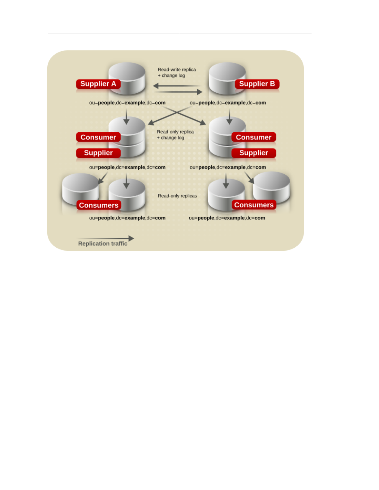
Chapter 6. Designing the Replication Process
86
Figure 6.8. Combined Multi-Master and Cascading Replication
6.3. Defining a Replication Strategy
The replication strategy is determined by the services that must be provided. To determine the
replication strategy, start by performing a survey of the network, users, applications, and how they use
the directory service.
• Assess the resources within the network, the traffic loads, and resource requirements for the
directory service.
See Section 6.3.1, “Conducting a Replication Survey”, Section 6.3.3, “Replication Resource
Requirements”, and Section 6.3.4, “Managing Disk Space Required for Multi-Master Replication”.
• If there are multiple consumers for different locations or sections of the company or if some servers
are insecure, then use fractional replication to exclude sensitive or seldom-modified information to
maintain data integrity without compromising sensitive information.
See Section 6.3.2, “Replicated Selected Attributes with Fractional Replication” for more information.
• If the network is stretched across a wide geographical area, there are multiple Directory Servers at
multiple sites, with local data masters connected by multi-master replication.
See Section 6.3.5, “Replication Across a Wide-Area Network” for more information.
Page 97

Conducting a Replication Survey
87
• If high availability is the primary concern, create a data center with multiple Directory Servers on a
single site. Single-master replication provides read-failover, while multi-master replication provides
write-failover.
See Section 6.3.6, “Using Replication for High Availability” for more information.
• If local availability is the primary concern, use replication to distribute data geographically to
Directory Servers in local offices around the world. A master copy of all information can be
maintained in a single location, such as the company headquarters, or each local site can manage
the parts of the DIT that are relevant for them.
See Section 6.3.7, “Using Replication for Local Availability” for more information.
• In all cases, balance the load of requests serviced by the Directory Servers and avoid network
congestion.
See Section 6.3.8, “Using Replication for Load Balancing” for more information.
After planning the replication strategy, it is possible to deploy the directory service. It is best to deploy
the directory service in stages, because this allows administrators to adjust the directory service
according to the loads that the enterprise places on the directory service. Unless the load analysis
is based on an already operating directory, be prepared to alter the directory services as the real-life
demands on the directory become clear.
6.3.1. Conducting a Replication Survey
Gather information about the network quality and usage in the site survey to help define the replication
strategy:
• The quality of the LANs and WANs connecting different buildings or remote sites and the amount of
available bandwidth.
• The physical location of users, how many users are at each site, and their usage patterns; i.e., how
they intend to use the directory service.
• The number of applications that access the directory service and the relative percentage of read,
search, and compare operations to write operations.
• If the messaging server uses the directory, find out how many operations it performs for each email
message it handles. Other products that rely on the directory service are typically products such as
authentication applications or meta-directory applications. For each one, determine the type and
frequency of operations that are performed in the directory service.
• The number and size of the entries stored in the directory service.
A site that manages human resource databases or financial information is likely to put a heavier
load on the directory service than a site containing engineering staff that uses the directory solely for
telephone book purposes.
6.3.2. Replicated Selected Attributes with Fractional Replication
Fractional replication allows the administrator to choose a set of attributes that are not transmitted
from a supplier to the consumer (or another supplier). Administrators can therefore replicate a
database without replicating all the information that it contains.
Page 98

Chapter 6. Designing the Replication Process
88
Fractional replication is enabled and configured per replication agreement. The exclusion of attributes
is applied equally to all entries. As far as the consumer server is concerned, the excluded attributes
always have no value. Therefore, a client performing a search against the consumer server never
sees the excluded attributes. Similarly, should it perform a search that specifies those attributes in its
filter, no entries match.
Fractional replication is particularly useful in the following situations:
• Where the consumer server is connected via a slow network, excluding infrequently changed
attributes or larger attributes such as jpegPhoto results in less network traffic.
• Where the consumer server is placed on an untrusted network such as the public Internet, excluding
sensitive attributes such as telephone numbers provides an extra level of protection that guarantees
no access to those attributes even if the server's access control measures are defeated or the
machine is compromised by an attacker.
Configuring fractional replication is described in the replication agreement and supplier configuration
sections in chapter 8, "Managing Replication," in the Administrator's Guide.
6.3.3. Replication Resource Requirements
Using replication requires more resources. Consider the following resource requirements when
defining the replication strategy:
• Disk usage — On supplier servers, the changelog is written after each update operation. Supplier
servers that receive many update operations may experience higher disk usage.
NOTE
Each supplier server uses a single changelog. If a supplier contains multiple replicated
databases, the changelog is used more frequently, and the disk usage is even higher.
• Server threads — Each replication agreement consumes one server thread. So, the number of
threads available to client applications is reduced, possibly affecting the server performance for the
client applications.
• File descriptors — The number of file descriptors available to the server is reduced by the
changelog (one file descriptor) and each replication agreement (one file descriptor per agreement).
6.3.4. Managing Disk Space Required for Multi-Master Replication
Multi-master replicas maintain additional logs, including the changelog of directory edits, state
information for update entries, and tombstone entries for deleted entries. This information is required
for multi-master replication to be performed. Because these log files can get very large, periodically
cleaning up these files is necessary to keep from wasting disk space.
There are four attributes which can configure the changelog maintenance for the multi-master replica.
Two are under cn=changelog5 and relate directly to trimming the changelog:
• nsslapd-changelogmaxage sets the maximum age that the entries in the changelog can
be; once an entry is older than that limit, it is deleted. This keeps the changelog from growing
indefinitely.
Page 99

Replication Across a Wide-Area Network
89
• nsslapd-changelogmaxentries sets the maximum number of entries that are allowed in the
changelog. Like nsslapd-changelogmaxage, this also trims the changelog, but be careful about
the setting. This must be large enough to allow a complete set of directory information or multimaster replication may not function properly.
The other two attributes are under the replication agreement entry in cn=replica, cn="suffixDN",
cn=mapping tree, cn=config. These two attributes relate to maintenance information kept in the
changelog, the tombstone and state information, rather than the directory edits information.
• nsDS5ReplicaPurgeDelay sets the maximum age that tombstone (deleted) entries and state
information can be in the changelog. Once a tombstone or state information entry is older than
that age, it is deleted. This differs from the nsslapd-changelogmaxage attribute in that the
nsDS5ReplicaPurgeDelay value applies only to tombstone and state information entries;
nsslapd-changelogmaxage applies to every entry in the changelog, including directory
modifications.
• nsDS5ReplicaTombstonePurgeInterval sets the frequency which the server runs a purge
operation. At this interval, the Directory Server runs an internal operation to clean the tombstone
and state entries out of the changelog. Make sure that the maximum age is longer than the longest
replication update schedule or multi-master replication may not be able to update replicas properly.
The parameters for managing replication and the changelog are described in chapter 2, "Core
Configuration Attributes," in the Configuration, Command, and File Reference.
6.3.5. Replication Across a Wide-Area Network
Wide-area networks typically have higher latency, a higher bandwidth-delay product, and lower speeds
than local area networks . Directory Server version 7.1 and later support efficient replication when a
supplier and consumer are connected via a wide-area network.
In previous versions of Directory Server, the replication protocols that were used to transmit entries
and updates between suppliers and consumers were highly latency-sensitive, because the supplier
would send only one update operation and then wait for a response from the consumer. This led to
reduced throughput with higher latencies.
Since version 7.1, the supplier sends many updates and entries to the consumer without waiting for a
response. Thus, on a network with high latency, many replication operations can be in transit on the
network, and replication throughput is similar to that which can be achieved on a local area network.
NOTE
If a supplier is connected to another supplier running an earlier version of Directory
Server, it falls back to the old replication mechanism for compatibility. It is therefore
necessary to run at least version 7.1 on both the supplier and consumer servers in order
to achieve the benefits of the new latency-insensitive replication.
There are both performance and security issues to consider for both the Directory Server and the
efficiency of the network connection:
• Where replication is performed across a public network such as the Internet, the use of SSL is
highly recommended. This guards against eavesdropping of the replication traffic.
• Use a T-1 or faster Internet connection for the network.
Page 100

Chapter 6. Designing the Replication Process
90
• When creating agreements for replication over a wide-area network, avoid constant synchronization
between the servers. Replication traffic could consume a large portion of the bandwidth and slow
down the overall network and Internet connections.
• When initializing consumers, do not to initialize the consumer immediately; instead, utilize file
system replica initialization, which is much faster than online initialization or initializing from file.
Refer to the Red Hat Directory Server Administrator's Guide for information on using filesystem
replica initialization.
6.3.6. Using Replication for High Availability
Use replication to prevent the loss of a single server from causing the directory service to become
unavailable. At a minimum, replicate the local directory tree to at least one backup server.
Some directory architects argue that information should be replicated three times per physical
location for maximum data reliability. The extent to use replication for fault tolerance depends on the
environment and personal preferences, but base this decision on the quality of the hardware and
networks used by the directory service. Unreliable hardware requires more backup servers.
NOTE
Do not use replication as a replacement for a regular data backup policy. For information
on backing up the directory data, refer to the Red Hat Directory Server Administrator's
Guide.
To guarantee write-failover for all directory clients, use a multi-master replication scenario. If readfailover is sufficient, use single-master replication.
LDAP client applications can usually be configured to search only one LDAP server. Unless there is
a custom client application to rotate through LDAP servers located at different DNS hostnames, the
LDAP client applications can only be configured to look up a single DNS hostname for a Directory
Server. Therefore, it is probably necessary to use either DNS round-robins or network sorts to provide
failover to the backup Directory Servers. For information on setting up and using DNS round-robins or
network sorts, refer to the DNS documentation.
6.3.7. Using Replication for Local Availability
The necessity of replicating for local availability is determined by the quality of the network as well as
the activities of the site. In addition, carefully consider the nature of the data contained in the directory
service and the consequences to the enterprise if that data were to become temporarily unavailable.
The more mission-critical the data, the less tolerant the system is of outages caused by poor network
connections.
Use replication for local availability for the following reasons:
• To keep a local master copy of the data.
This is an important strategy for large, multinational enterprises that need to maintain directory
information of interest only to the employees in a specific country. Having a local master copy of the
data is also important to any enterprise where interoffice politics dictate that data be controlled at a
divisional or organizational level.
• To mitigate unreliable or intermittently available network connections.
 Loading...