

Page 1

Red Hat Cluster Suite
Configuring and Managing a
Cluster
Page 2

Red Hat Cluster Suite: Configuring and Managing a Cluster
Copyright © 2000-2004 Red Hat, Inc.Mission Critical Linux, Inc.K.M. Sorenson
Red Hat, Inc.
1801 Varsity Drive
Raleigh NC 27606-2072 USA
Phone: +1 919 754 3700
Phone: 888 733 4281
Fax: +1 919 754 3701
PO Box 13588
Research Triangle Park NC 27709 USA
rh-cs(EN)-3-Print-RHI (2006-02-03T16:44)
For Part I Using the Red Hat Cluster Manager and Part III Appendixes, permission is granted to copy, distribute and/ormodify
this document under the terms of the GNU Free DocumentationLicense, Version 1.1 or any later version published by theFree
Software Foundation.A copy of the license is availableat http://www.gnu.org/licenses/fdl.html. The content described in this
paragraph is copyrighted by © Mission Critical Linux, Inc. (2000), K.M. Sorenson (2000), and Red Hat, Inc. (2000-2003).
This material in Part II Configuring a Linux Virtual Server Cluster may be distributed only subject to the terms and conditions
set forth in the Open PublicationLicense, V1.0 or later (the latest version is presently available at
http://www.opencontent.org/openpub/). Distribution of substantively modified versions of this material is prohibitedwithout
the explicit permissionof the copyright holder. Distribution of the work or derivative of the work in any standard(paper) book
form for commercial purposes is prohibited unless prior permission is obtained from the copyright holder. The content
described in this paragraph is copyrightedby © Red Hat, Inc. (2000-2003).
Red Hat and the Red Hat "Shadow Man" logo are registered trademarks of Red Hat, Inc. in the United States and other
countries.
All other trademarks referencedherein are the property of their respective owners.
The GPG fingerprint of the security@redhat.comkey is:
CA 20 86 86 2B D6 9D FC 65 F6 EC C4 21 91 80 CD DB 42 A6 0E
Page 3

Table of Contents
Acknowledgments ................................................................................................................................ i
Introduction........................................................................................................................................ iii
1. How To Use This Manual .................................................................................................... iii
2. Document Conventions ........................................................................................................ iv
3. More to Come ...................................................................................................................... vi
3.1. Send in Your Feedback ......................................................................................... vi
4. Activate Your Subscription ................................................................................................. vii
4.1. Provide a Red Hat Login...................................................................................... vii
4.2. Provide Your Subscription Number ..................................................................... vii
4.3. Connect Your System..........................................................................................viii
I. Using the Red Hat Cluster Manager ............................................................................................ ix
1. Red Hat Cluster Manager Overview..................................................................................... 1
1.1. Red Hat Cluster Manager Features ........................................................................ 2
2. Hardware Installation and Operating System Configuration ................................................ 5
2.1. Choosing a Hardware Configuration ..................................................................... 5
2.2. Setting Up the Members ...................................................................................... 15
2.3. Installing and Configuring Red Hat Enterprise Linux ......................................... 17
2.4. Setting Up and Connecting the Cluster Hardware ............................................... 21
3. Cluster Configuration .......................................................................................................... 35
3.1. Installing the Red Hat Cluster Suite Packages ..................................................... 35
3.2. Installation Notes for Red Hat Enterprise Linux 2.1 Users ................................. 37
3.3. The Cluster Configuration Tool ........................................................................ 37
3.4. Configuring the Cluster Software ........................................................................ 40
3.5. Editing the rawdevices File .............................................................................. 41
3.6. Configuring Cluster Daemons.............................................................................. 42
3.7. Adding and Deleting Members ............................................................................ 46
3.8. Configuring a Power Controller Connection ....................................................... 48
3.9. Configuring a Failover Domain ........................................................................... 49
3.10. Adding a Service to the Cluster ......................................................................... 51
3.11. Checking the Cluster Configuration................................................................... 54
3.12. Configuring syslogd Event Logging ............................................................... 56
4. Service Administration ....................................................................................................... 59
4.1. Configuring a Service .......................................................................................... 59
4.2. Displaying a Service Configuration ..................................................................... 62
4.3. Disabling a Service .............................................................................................. 63
4.4. Enabling a Service ............................................................................................... 63
4.5. Modifying a Service ............................................................................................. 63
4.6. Relocating a Service ............................................................................................ 64
4.7. Deleting a Service ................................................................................................ 64
4.8. Handling Failed Services ..................................................................................... 64
5. Database Services ............................................................................................................... 67
5.1. Setting Up an Oracle Service ............................................................................... 67
5.2. Tuning Oracle Service ......................................................................................... 72
5.3. Setting Up a MySQL Service .............................................................................. 73
6. Network File Sharing Services ........................................................................................... 77
6.1. Setting Up an NFS Service .................................................................................. 77
6.2. Using the NFS Druid .......................................................................................... 77
6.3. NFS Caveats......................................................................................................... 82
6.4. Importing the Contents of an NFS Exports File .................................................. 82
6.5. NFS Configuration: Active-Active Example ....................................................... 83
6.6. Setting Up a Samba Service ................................................................................. 84
6.7. Using the Samba Druid ........................................................................................ 86
6.8. Fields in the smb.conf.sharename File ........................................................... 90
Page 4

7. Setting Up Apache HTTP Server ........................................................................................ 93
7.1. Apache HTTP Server Setup Overview ................................................................ 93
7.2. Configuring Shared Storage ................................................................................. 93
7.3. Installing and Configuring the Apache HTTP Server .......................................... 94
8. Cluster Administration ........................................................................................................ 97
8.1. Overview of the Cluster Status Tool.................................................................. 97
8.2. Displaying Cluster and Service Status ................................................................. 97
8.3. Starting and Stopping the Cluster Software ......................................................... 99
8.4. Modifying the Cluster Configuration................................................................. 100
8.5. Backing Up and Restoring the Cluster Database ............................................... 100
8.6. Modifying Cluster Event Logging ..................................................................... 101
8.7. Updating the Cluster Software........................................................................... 101
8.8. Changing the Cluster Name ............................................................................... 102
8.9. Disabling the Cluster Software .......................................................................... 102
8.10. Diagnosing and Correcting Problems in a Cluster ........................................... 102
II. Configuring a Linux Virtual Server Cluster ........................................................................... 107
9. Introduction to Linux Virtual Server................................................................................. 109
9.1. Technology Overview........................................................................................ 109
9.2. Basic Configurations .......................................................................................... 109
10. Linux Virtual Server Overview....................................................................................... 111
10.1. A Basic LVS Configuration ............................................................................. 111
10.2. A Three Tiered LVS Configuration.................................................................. 113
10.3. LVS Scheduling Overview ............................................................................... 114
10.4. Routing Methods.............................................................................................. 116
10.5. Persistence and Firewall Marks ....................................................................... 118
10.6. LVS Cluster — A Block Diagram ................................................................... 118
11. Initial LVS Configuration................................................................................................ 121
11.1. Configuring Services on the LVS Routers ....................................................... 121
11.2. Setting a Password for the Piranha Configuration Tool ............................... 122
11.3. Starting the Piranha Configuration Tool Service .......................................... 122
11.4. Limiting Access To the Piranha Configuration Tool.................................... 123
11.5. Turning on Packet Forwarding......................................................................... 124
11.6. Configuring Services on the Real Servers ....................................................... 124
12. Setting Up a Red Hat Enterprise Linux LVS Cluster...................................................... 125
12.1. The NAT LVS Cluster ...................................................................................... 125
12.2. Putting the Cluster Together ............................................................................ 127
12.3. Multi-port Services and LVS Clustering .......................................................... 128
12.4. FTP In an LVS Cluster ..................................................................................... 130
12.5. Saving Network Packet Filter Settings ............................................................ 132
13. Configuring the LVS Routers with Piranha Configuration Tool ................................. 133
13.1. Necessary Software.......................................................................................... 133
13.2. Logging Into the Piranha Configuration Tool .............................................. 133
13.3. CONTROL/MONITORING......................................................................... 134
13.4. GLOBAL SETTINGS ................................................................................... 135
13.5. REDUNDANCY............................................................................................. 137
13.6. VIRTUAL SERVERS .................................................................................... 139
13.7. Synchronizing Configuration Files .................................................................. 147
13.8. Starting the Cluster .......................................................................................... 148
Page 5

III. Appendixes................................................................................................................................ 149
A. Using Red Hat Cluster Manager with Piranha ................................................................. 151
B. Using Red Hat GFS with Red Hat Cluster Suite.............................................................. 153
B.1. Terminology ...................................................................................................... 153
B.2. Changes to Red Hat Cluster .............................................................................. 154
B.3. Installation Scenarios ........................................................................................ 154
C. The GFS Setup Druid ....................................................................................................... 157
C.1. Cluster Name..................................................................................................... 157
C.2. LOCK_GULM parameters .................................................................................. 157
C.3. Choose Location for CCS Files ......................................................................... 158
C.4. Cluster Members ............................................................................................... 159
C.5. Saving Your Configuration and Next Steps....................................................... 161
D. Supplementary Hardware Information ............................................................................. 163
D.1. Setting Up Power Controllers ........................................................................... 163
D.2. SCSI Bus Configuration Requirements ............................................................ 165
D.3. SCSI Bus Termination ...................................................................................... 166
D.4. SCSI Bus Length............................................................................................... 166
D.5. SCSI Identification Numbers ............................................................................ 167
E. Supplementary Software Information .............................................................................. 169
E.1. Cluster Communication Mechanisms................................................................ 169
E.2. Failover and Recovery Scenarios ...................................................................... 170
E.3. Common Cluster Behaviors: General ................................................................ 170
E.4. Common Behaviors: Two Member Cluster with Disk-based Tie-breaker ........172
E.5. Common Behaviors: 2-4 Member Cluster with IP-based Tie-Breaker ............. 173
E.6. Common Behaviors: 3-5 Member Cluster ........................................................ 173
E.7. Common Behaviors: Cluster Service Daemons ................................................ 174
E.8. Common Behaviors: Miscellaneous .................................................................. 175
E.9. The cluster.xml File ..................................................................................... 175
F. Cluster Command-line Utilities ........................................................................................ 179
F.1. Using redhat-config-cluster-cmd ........................................................... 179
F.2. Using the shutil Utility ................................................................................... 180
F.3. Using the clusvcadm Utility ............................................................................ 180
F.4. Using the clufence Utility .............................................................................. 181
Index................................................................................................................................................. 183
Colophon.......................................................................................................................................... 191
Page 6

Page 7

Acknowledgments
The Red Hat Cluster Manager software was originally based on the open source Kimberlite
(http://oss.missioncriticallinux.com/kimberlite/) cluster project, which was developed by Mission
Critical Linux, Inc.
Subsequent to its inception based on Kimberlite, developers at Red Hat have made a large number
of enhancements and modifications. The following is a non-comprehensive list highlighting some of
these enhancements.
• Packaging and integration into the Red Hat installation paradigm to simplify the end user’s experi-
ence.
• Addition of support for multiple cluster members.
• Addition of support for high availability NFS services.
• Addition of support for high availability Samba services.
• Addition of the Cluster Configuration Tool, a graphical configuration tool.
• Addition of the Cluster Status Tool, a graphical monitoring and administration tool.
• Addition of support for failover domains.
• Addition of support for Red Hat GFS, including the GFS Setup Druid and the LOCK_GULM
fencing driver.
• Addition of support for using watchdog timers as a data integrity provision.
• Addition of service monitoring which automatically restart a failed application.
• Rewrite of the service manager to facilitate additional cluster-wide operations.
• A set of miscellaneous bug fixes.
The Red Hat Cluster Manager software incorporates STONITH compliant power switch modules
from the Linux-HA project; refer to http://www.linux-ha.org/stonith/.
Page 8

ii Acknowledgments
Page 9

Introduction
The Red Hat Cluster Suite is a collection of technologies working together to provide data integrity
and the ability to maintain application availability in the event of a failure. Administrators can deploy
enterprise cluster solutions using a combination of hardware redundancy along with the failover and
load-balancing technologies in Red Hat Cluster Suite.
Red Hat Cluster Manager is a high-availability cluster solution specifically suited for database applications, network file servers, and World Wide Web (Web) servers with dynamic content. An Red Hat
Cluster Manager system features data integrity and application availability using redundant hardware,
shared disk storage, power management, and robust cluster communication and application failover
mechanisms.
Administrators can also deploy highly available applications services using Piranha, a load-balancing
and advanced routing cluster solution based on Linux Virtual Server (LVS) technology. Using
Piranha, administrators can build highly available e-commerce sites that feature complete
data integrity and service availability, in addition to load balancing capabilities. Refer to
Part II Configuring a Linux Virtual Server Cluster for more information.
This guide assumes that the user has an advanced working knowledge of Red Hat Enterprise Linux and
understands the concepts of server computing. For more information about using Red Hat Enterprise
Linux, refer to the following resources:
• Red Hat Enterprise Linux Installation Guide for information regarding installation.
• Red Hat Enterprise Linux Introduction to System Administration for introductory information for
new Red Hat Enterprise Linux system administrators.
• Red Hat Enterprise Linux System Administration Guide for more detailed information about con-
figuring Red Hat Enterprise Linux to suit your particular needs as a user.
• Red Hat Enterprise Linux Reference Guide provides detailed information suited for more experi-
enced users to refer to when needed, as opposed to step-by-step instructions.
• Red Hat Enterprise Linux Security Guide details the planning and the tools involved in creating a
secured computing environment for the data center, workplace, and home.
HTML, PDF, and RPM versions of the manuals are available on the Red Hat Enterprise Linux Documentation CD and online at:
http://www.redhat.com/docs/
1. How To Use This Manual
This manual contains information about setting up a Red Hat Cluster Manager system. These
tasks are described in Chapter 2 Hardware Installation and Operating System Configuration and
Chapter 3 Cluster Configuration.
For information about configuring Red Hat Cluster Manager cluster services, refer to
Chapter 4 Service Administration through Chapter 7 Setting Up Apache HTTP Server.
Part II Configuring a Linux Virtual Server Cluster describes how to achieve load balancing in an Red
Hat Enterprise Linux cluster by using the Linux Virtual Server.
For information about deploying a Red Hat Cluster Manager cluster in conjunction with Red Hat GFS
using the GFS Setup Druid, refer to Appendix C The GFS Setup Druid.
Appendix D Supplementary Hardware Information contains detailed configuration
information on specific hardware devices and shared storage configurations.
Appendix E Supplementary Software Information contains background information on the cluster
software and other related information.
Page 10

iv Introduction
Appendix F Cluster Command-line Utilities provides usage and reference information on the
command-line utilities included with Red Hat Cluster Suite.
This guide assumes you have a thorough understanding of Red Hat Enterprise Linux system administration concepts and tasks. For detailed information on Red Hat Enterprise Linux system administration, refer to the Red Hat Enterprise Linux System Administration Guide. For reference information
on Red Hat Enterprise Linux, refer to the Red Hat Enterprise Linux Reference Guide.
2. Document Conventions
When you read this manual, certain words are represented in different fonts, typefaces, sizes, and
weights. This highlighting is systematic; different words are represented in the same style to indicate
their inclusion in a specific category. The types of words that are represented this way include the
following:
command
Linux commands (and other operating system commands, when used) are represented this way.
This style should indicate to you that you can type the word or phrase on the command line
and press [Enter] to invoke a command. Sometimes a command contains words that would be
displayed in a different style on their own (such as file names). In these cases, they are considered
to be part of the command, so the entire phrase is displayed as a command. For example:
Use the cat testfile command to view the contents of a file, named testfile, in the current
working directory.
file name
File names, directory names, paths, and RPM package names are represented this way. This style
should indicate that a particular file or directory exists by that name on your system. Examples:
The .bashrc file in your home directory contains bash shell definitions and aliases for your own
use.
The /etc/fstab file contains information about different system devices and file systems.
Install the webalizer RPM if you want to use a Web server log file analysis program.
application
This style indicates that the program is an end-user application (as opposed to system software).
For example:
Use Mozilla to browse the Web.
[key]
A key on the keyboard is shown in this style. For example:
To use [Tab] completion, type in a character and then press the [Tab] key. Your terminal displays
the list of files in the directory that start with that letter.
[key]-[combination]
A combination of keystrokes is represented in this way. For example:
The [Ctrl]-[Alt]-[Backspace] key combination exits your graphical session and return you to the
graphical login screen or the console.
Page 11

Introduction v
text found on a GUI interface
A title, word, or phrase found on a GUI interface screen or window is shown in this style. Text
shown in this style is being used to identify a particular GUI screen or an element on a GUI
screen (such as text associated with a checkbox or field). Example:
Select the Require Password checkbox if you would like your screensaver to require a password
before stopping.
top level of a menu on a GUI screen or window
A word in this style indicates that the word is the top level of a pulldown menu. If you click on
the word on the GUI screen, the rest of the menu should appear. For example:
Under File on a GNOME terminal, the New Tab option allows you to open multiple shell
prompts in the same window.
If you need to type in a sequence of commands from a GUI menu, they are shown like the
following example:
Go to Main Menu Button (on the Panel) => Programming => Emacs to start the Emacs text
editor.
button on a GUI screen or window
This style indicates that the text can be found on a clickable button on a GUI screen. For example:
Click on the Back button to return to the webpage you last viewed.
computer output
Text in this style indicates text displayed to a shell prompt such as error messages and responses
to commands. For example:
The ls command displays the contents of a directory. For example:
Desktop about.html logs paulwesterberg.png
Mail backupfiles mail reports
The output returned in response to the command (in this case, the contents of the directory) is
shown in this style.
prompt
A prompt, which is a computer’s way of signifying that it is ready for you to input something, is
shown in this style. Examples:
$
#
[stephen@maturin stephen]$
leopard login:
user input
Text that the user has to type, either on the command line, or into a text box on a GUI screen, is
displayed in this style. In the following example, text is displayed in this style:
To boot your system into the text based installation program, you must type in the text command at the boot: prompt.
replaceable
Text used for examples, which is meant to be replaced with data provided by the user, is displayed
in this style. In the following example, <version-number> is displayed in this style:
Page 12

vi Introduction
The directory for the kernel source is /usr/src/<version-number>/, where
<version-number> is the version of the kernel installed on this system.
Additionally, we use several different strategies to draw your attention to certain pieces of information.
In order of how critical the information is to your system, these items are marked as a note, tip,
important, caution, or warning. For example:
Note
Remember that Linux is case sensitive. In other words, a rose is not a ROSE is not a rOsE.
Tip
The directory /usr/share/doc/ contains additional documentation for packages installed on your
system.
Important
If you modify the DHCP configuration file, the changes do not take effect until you restart the DHCP
daemon.
Caution
Do not perform routine tasks as root — use a regular user account unless you need to use the root
account for system administration tasks.
Warning
Be careful to remove only the necessary Red Hat Enterprise Linux partitions. Removing other par titions could result in data loss or a corrupted system environment.
3. More to Come
This manual is part of Red Hat’s growing commitment to provide useful and timely support to Red
Hat Enterprise Linux users.
Page 13

Introduction vii
3.1. Send in Your Feedback
If you spot a typo, or if you have thought of a way to make this manual better, we would love to
hear from you. Please submit a report in Bugzilla (http://bugzilla.redhat.com/bugzilla/) against the
component rh-cs.
Be sure to mention the manual’s identifier:
rh-cs(EN)-3-Print-RHI (2006-02-03T16:44)
By mentioning this manual’s identifier, we know exactly which version of the guide you have.
If you have a suggestion for improving the documentation, try to be as specific as possible. If you
have found an error, please include the section number and some of the surrounding text so we can
find it easily.
4. Activate Your Subscription
Before you can access service and software maintenance information, and the support documentation included in your subscription, you must activate your subscription by registering with Red Hat.
Registration includes these simple steps:
• Provide a Red Hat login
• Provide a subscription number
• Connect your system
The first time you boot your installation of Red Hat Enterprise Linux, you are prompted to register
with Red Hat using the Setup Agent. If you follow the prompts during the Setup Agent, you can
complete the registration steps and activate your subscription.
If you can not complete registration during the Setup Agent (which requires network access), you
can alternatively complete the Red Hat registration process online at http://www.redhat.com/register/.
4.1. Provide a Red Hat Login
If you do not have an existing Red Hat login, you can create one when prompted during the Setup
Agent or online at:
https://www.redhat.com/apps/activate/newlogin.html
A Red Hat login enables your access to:
• Software updates, errata and maintenance via Red Hat Network
• Red Hat technical support resources, documentation, and Knowledgebase
If you have forgotten your Red Hat login, you can search for your Red Hat login online at:
https://rhn.redhat.com/help/forgot_password.pxt
Page 14

viii Introduction
4.2. Provide Your Subscription Number
Your subscription number is located in the package that came with your order. If your package did not
include a subscription number, your subscription was activated for you and you can skip this step.
You can provide your subscription number when prompted during the Setup Agent or by visiting
http://www.redhat.com/register/.
4.3. Connect Your System
The Red Hat Network Registration Client helps you connect your system so that you can begin to get
updates and perform systems management. There are three ways to connect:
1. During the Setup Agent — Check the Send hardware information and Send system package
list options when prompted.
2. After the Setup Agent has been completed — From the Main Menu, go to System Tools, then
select Red Hat Network.
3. After the Setup Agent has been completed — Enter the following command from the command
line as the root user:
• /usr/bin/up2date --register
Page 15

I. Using the Red Hat Cluster Manager
Clustered systems provide reliability, scalability, and availability to critical production services. Using
the Red Hat Cluster Manager, administrators can create high availability clusters for filesharing, Web
servers, databases, and more. This part discusses the installation and configuration of cluster systems
using the recommended hardware and Red Hat Enterprise Linux.
This section is licensed under the GNU Free Documentation License. For details refer to the Copyright
page.
Table of Contents
1. Red Hat Cluster Manager Overview............................................................................................. 1
2. Hardware Installation and Operating System Configuration .................................................... 5
3. Cluster Configuration ................................................................................................................... 35
4. Service Administration ................................................................................................................. 59
5. Database Services .......................................................................................................................... 67
6. Network File Sharing Services ..................................................................................................... 77
7. Setting Up Apache HTTP Server ................................................................................................ 93
8. Cluster Administration................................................................................................................. 97
Page 16

Page 17
Chapter 1.
Red Hat Cluster Manager Overview
Red Hat Cluster Manager allows administrators to connect separate systems (called members or
nodes) together to create failover clusters that ensure application availability and data integrity under
several failure conditions. Administrators can use Red Hat Cluster Manager with database applications, file sharing services, web servers, and more.
To set up a failover cluster, you must connect the member systems (often referred to simply as mem-
bers or nodes) to the cluster hardware, and configure the members into the cluster environment. The
foundation of a cluster is an advanced host membership algorithm. This algorithm ensures that the
cluster maintains complete data integrity at all times by using the following methods of inter-member
communication:
• Network connections between the cluster systems for heartbeat
• Shared state on shared disk storage to hold cluster status
To make an application and data highly available in a cluster, you must configure a service (such
as an application and shared disk storage) as a discrete, named group of properties and resources to
which you can assign an IP address to provide transparent client access. For example, you can set up
a service that provides clients with access to highly-available database application data.
You can associate a service with a failover domain, a subset of cluster members that are eligible to
run the service. In general, any eligible member can run the service and access the service data on
shared disk storage. However, each service can run on only one cluster member at a time, in order to
maintain data integrity. You can specify whether or not the members in a failover domain are ordered
by preference. You can also specify whether or not a service is restricted to run only on members of
its associated failover domain. (When associated with an unrestricted failover domain, a service can
be started on any cluster member in the event no member of the failover domain is available.)
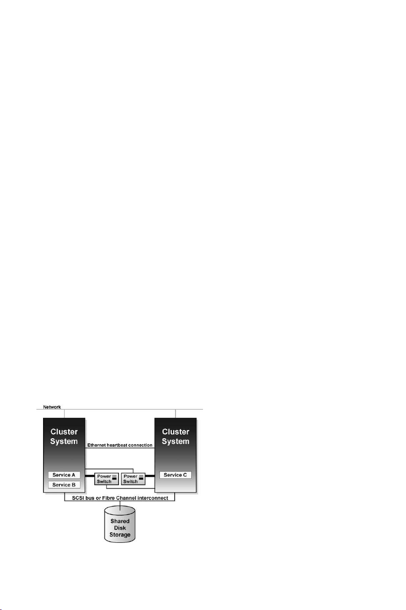
You can set up an active-active configuration in which the members run different services simultaneously, or a hot-standby configuration in which a primary member runs all the services, and a backup
cluster system takes over only if the primary system fails.
Figure 1-1 shows an example of a cluster in an active-active configuration.
Figure 1-1. Example Cluster in Active-Active Configuration
Page 18

2 Chapter 1. Red Hat Cluster Manager Overview
If a hardware or software failure occurs, the cluster automatically restarts the failed member’s services
on the functional member. This service failover capability ensures that no data is lost, and there is little
disruption to users. When the failed member recovers, the cluster can re-balance the services across
the members.
In addition, you can cleanly stop the services running on a cluster system and then restart them on
another system. This service relocation capability allows you to maintain application and data availability when a cluster member requires maintenance.
1.1. Red Hat Cluster Manager Features
Cluster systems deployed with Red Hat Cluster Manager include the following features:
No-single-point-of-failure hardware configuration
Clusters can include a dual-controller RAID array, multiple network channels, and redundant
uninterruptible power supply (UPS) systems to ensure that no single failure results in application
down time or loss of data.
Alternately, a low-cost cluster can be set up to provide less availability than a no-single-pointof-failure cluster. For example, you can set up a cluster with a single-controller RAID array and
only a single Ethernet channel.
Certain low-cost alternatives, such as software RAID and multi-initiator parallel SCSI, are not
compatible or appropriate for use on the shared cluster storage. Refer to Section 2.1 Choosing a
Hardware Configuration, for more information.
Service configuration framework
Clusters allow you to easily configure individual services to make data and applications highly
available. To create a service, you specify the resources used in the service and properties for
the service, including the service name, application start, stop, and status script, disk partitions,
mount points, and the cluster members on which you prefer the service to run. After you add a
service, the cluster management software stores the information in a cluster configuration file on
shared storage, where the configuration data can be accessed by all cluster members.
The cluster provides an easy-to-use framework for database applications. For example, a database
service serves highly-available data to a database application. The application running on a cluster member provides network access to database client systems, such as Web servers. If the
service fails over to another member, the application can still access the shared database data. A
network-accessible database service is usually assigned an IP address, which is failed over along
with the service to maintain transparent access for clients.
The cluster service framework can be easily extended to other applications, as well.
Failover domains
By assigning a service to a restricted failover domain, you can limit the members that are eligible
to run a service in the event of a failover. (A service that is assigned to a restricted failover
domain cannot be started on a cluster member that is not included in that failover domain.) You
can order the members in a failover domain by preference to ensure that a particular member
runs the service (as long as that member is active). If a service is assigned to an unrestricted
failover domain, the service starts on any available cluster member (if none of the members of
the failover domain are available).
Data integrity assurance
To ensure data integrity, only one member can run a service and access service data at one
time. The use of power switches in the cluster hardware configuration enables a member to
power-cycle another member before restarting that member’s services during the failover process.
Page 19
Chapter 1. Red Hat Cluster Manager Overview 3
This prevents any two systems from simultaneously accessing the same data and corrupting it.
Although not required, it is recommended that power switches are used to guarantee data integrity
under all failure conditions. Watchdog timers are an optional variety of power control to ensure
correct operation of service failover.
Cluster administration user interface
The cluster administration interface facilitiates management tasks such as: creating, starting,
and stopping services; relocating services from one member to another; modifying the cluster
configuration (to add or remove services or resources); and monitoring the cluster members and
services.
Ethernet channel bonding
To monitor the health of the other members, each member monitors the health of the remote
power switch, if any, and issues heartbeat pings over network channels. With Ethernet channel
bonding, multiple Ethernet interfaces are configured to behave as one, reducing the risk of a
single-point-of-failure in the typical switched Ethernet connection between systems.
Shared storage for quorum information
Shared state information includes whether the member is active. Service state information includes whether the service is running and which member is running the service. Each member
checks to ensure that the status of the other members is up to date.
In a two-member cluster, each member periodically writes a timestamp and cluster state information to two shared cluster partitions located on shared disk storage. To ensure correct cluster
operation, if a member is unable to write to both the primary and shadow shared cluster partitions
at startup time, it is not allowed to join the cluster. In addition, if a member is not updating its
timestamp, and if heartbeats to the system fail, the member is removed from the cluster.
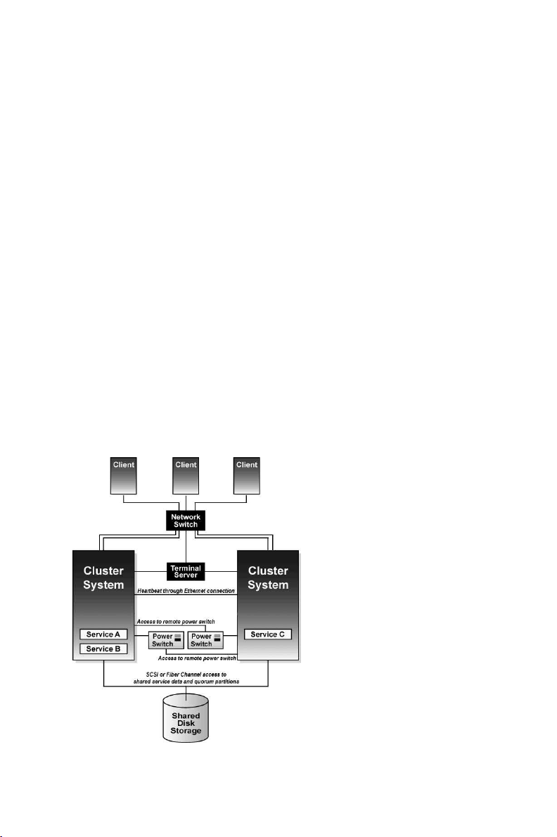
Figure 1-2 shows how members communicate in a cluster configuration. Note that the terminal
server used to access system consoles via serial ports is not a required cluster component.
Figure 1-2. Cluster Communication Mechanisms
Page 20

4 Chapter 1. Red Hat Cluster Manager Overview
Service failover capability
If a hardware or software failure occurs, the cluster takes the appropriate action to maintain
application availability and data integrity. For example, if a member completely fails, another
member (in the associated failover domain, if used, or in the cluster) restarts its services. Services
already running on this member are not disrupted.
When the failed member reboots and is able to write to the shared cluster partitions, it can rejoin
the cluster and run services. Depending on how the services are configured, the cluster can rebalance the services among the members.
Manual service relocation capability
In addition to automatic service failover, a cluster allows you to cleanly stop services on one
member and restart them on another member. You can perform planned maintenance on a member system while continuing to provide application and data availability.
Event logging facility
To ensure that problems are detected and resolved before they affect service availability, the cluster daemons log messages by using the conventional Linux syslog subsystem. You can customize
the severity level of the logged messages.
Application monitoring
The infrastructure in a cluster can optionally monitor the state and health of an application. In
this manner, should an application-specific failure occur, the cluster automatically restarts the
application. In response to the application failure, the application attempts to be restarted on the
member it was initially running on; failing that, it restarts on another cluster member. You can
specify which members are eligible to run a service by assigning a failover domain to the service.
Page 21

Chapter 2.
Hardware Installation and Operating System
Configuration
To set up the hardware configuration and install Red Hat Enterprise Linux, follow these steps:
• Choose a cluster hardware configuration that meets the needs of applications and users; refer to
Section 2.1 Choosing a Hardware Configuration.
• Set up and connect the members and the optional console switch and network switch or hub; refer
to Section 2.2 Setting Up the Members.
• Install and configure Red Hat Enterprise Linux on the cluster members; refer to
Section 2.3 Installing and Configuring Red Hat Enterprise Linux .
• Set up the remaining cluster hardware components and connect them to the members; refer to
Section 2.4 Setting Up and Connecting the Cluster Hardware.
After setting up the hardware configuration and installing Red Hat Enterprise Linux, install the cluster
software.
Tip
Refer to the Red Hat Hardware Compatibility List available at http://hardware.redhat.com/hcl/ for a
list of compatible hardware. Perform a Quick Search for the term cluster to find results for power
switch and shared storage hardware certified for or compatible with Red Hat Cluster Manager. For
general system hardware compatibility searches, use manufacturer, brand, and/or model keywords
to check for compatibility with Red Hat Enterprise Linux.
2.1. Choosing a Hardware Configuration
The Red Hat Cluster Manager allows administrators to use commodity hardware to set up a cluster
configuration that meets the performance, availability, and data integrity needs of applications and
users. Cluster hardware ranges from low-cost minimum configurations that include only the components required for cluster operation, to high-end configurations that include redundant Ethernet
channels, hardware RAID, and power switches.
Regardless of configuration, the use of high-quality hardware in a cluster is recommended, as hardware malfunction is a primary cause of system down time.
Although all cluster configurations provide availability, some configurations protect against every
single point of failure. In addition, all cluster configurations provide data integrity, but some configurations protect data under every failure condition. Therefore, administrators must fully understand the
needs of their computing environment and also the availability and data integrity features of different
hardware configurations to choose the cluster hardware that meets the proper requirements.
When choosing a cluster hardware configuration, consider the following:
Performance requirements of applications and users
Choose a hardware configuration that provides adequate memory, CPU, and I/O resources. Be
sure that the configuration chosen can handle any future increases in workload as well.
Page 22

6 Chapter 2. Hardware Installation and Operating System Configuration
Cost restrictions
The hardware configuration chosen must meet budget requirements. For example, systems with
multiple I/O ports usually cost more than low-end systems with fewer expansion capabilities.
Availability requirements
If a computing environment requires the highest degree of availability, such as a production
environment, then a cluster hardware configuration that protects against all single points of failure, including disk, storage interconnect, Ethernet channel, and power failures is recommended.
Environments that can tolerate an interruption in availability, such as development environments, may not require as much protection. Refer to Section 2.4.3 Configuring UPS Systems and
Section 2.4.4 Configuring Shared Disk Storagefor more information about using redundant hardware for high availability.
Data integrity under all failure conditions requirement
Using power switches in a cluster configuration guarantees that service data is protected under
every failure condition. These devices enable a member to power cycle another member before
restarting its services during failover. Power switches protect against data corruption if an unresponsive (or hanging) member becomes responsive after its services have failed over and then
issues I/O to a disk that is also receiving I/O from the other member.
In addition, if a quorum daemon fails on a member, the member is no longer able to monitor the
shared cluster partitions. If you are not using power switches in the cluster, this error condition
may result in services being run on more than one member, which can cause data corruption.
Refer to Section 2.4.2 Configuring Power Switches for more information about the benefits of
using power switches in a cluster. It is recommended that production environments use power
switches or watchdog timers in the cluster configuration.
2.1.1. Shared Storage Requirements
The operation of the cluster depends on reliable, coordinated access to shared storage. In the event
of hardware failure, it is desirable to be able to disconnect one member from the shared storage for
repair without disrupting the other members. Shared storage is truly vital to the cluster configuration.
Testing has shown that it is difficult, if not impossible, to configure reliable multi-initiator parallel
SCSI configurations at data rates above 80MB/sec using standard SCSI adapters. Further tests have
shown that these configurations cannot support online repair because the bus does not work reliably
when the HBA terminators are disabled, and external terminators are used. For these reasons, multiinitiator SCSI configurations using standard adapters are not supported. Either single-initiator SCSI
bus adapters (connected to multi-ported storage) or Fibre Channel adapters are required.
The Red Hat Cluster Manager requires that all cluster members have simultaneous access to the shared
storage. Certain host RAID adapters are capable of providing this type of access to shared RAID units.
These products require extensive testing to ensure reliable operation, especially if the shared RAID
units are based on parallel SCSI buses. These products typically do not allow for online repair of
a failed member. Only host RAID adapters listed in the Red Hat Hardware Compatibility List are
supported.
The use of software RAID, or software Logical Volume Management (LVM), is not supported on
shared storage. This is because these products do not coordinate access from multiple hosts to shared
storage. Software RAID or LVM may be used on non-shared storage on cluster members (for example,
boot and system partitions, and other file systems which are not associated with any cluster services).
2.1.2. Minimum Hardware Requirements
A minimum hardware configuration includes only the hardware components that are required for
cluster operation, as follows:
Page 23

Chapter 2. Hardware Installation and Operating System Configuration 7
• Two servers to run cluster services
• Ethernet connection for sending heartbeat pings and for client network access
• Shared disk storage for the shared cluster partitions and service data
The hardware components described in Table 2-1 can be used to set up a minimum cluster configuration. This configuration does not guarantee data integrity under all failure conditions, because it does
not include power switches. Note that this is a sample configuration; it is possible to set up a minimum
configuration using other hardware.
Warning
The minimum cluster configuration is not a supported solution and should not be used in a production
environment, as it does not guarantee data integrity under all failure conditions.
Hardware Description
Two servers Each member includes a network interface for client access and
for Ethernet connections and a SCSI adapter (termination
disabled) for the shared storage connection
Two network cables with RJ45
connectors
Network cables connect an Ethernet network interface on each
member to the network for client access and heartbeat pings.
RAID storage enclosure The RAID storage enclosure contains one controller with at least
two host ports.
Two HD68 SCSI cables Each cable connects one HBA to one port on the RAID
controller, creating two single-initiator SCSI buses.
Table 2-1. Example of Minimum Cluster Configuration
The minimum hardware configuration is the most cost-effective cluster configuration; however,
it includes multiple points of failure. For example, if the RAID controller fails, then all
cluster services become unavailable. When deploying the minimal hardware configuration,
software watchdog timers should be configured as a data integrity provision. Refer to
Section D.1.2.3 Configuring a Hardware Watchdog Timer for details.
To improve availability, protect against component failure, and guarantee data integrity under all failure conditions, the minimum configuration can be expanded, as described in Table 2-2.
Problem Solution
Disk failure Hardware RAID to replicate data across multiple disks
RAID controller failure Dual RAID controllers to provide redundant access to
disk data
Heartbeat failure Ethernet channel bonding and failover
Power source failure Redundant uninterruptible power supply (UPS) systems
Data corruption under all failure
Power switches or hardware-based watchdog timers
conditions
Table 2-2. Improving Availability and Guaranteeing Data Integrity
Page 24

8 Chapter 2. Hardware Installation and Operating System Configuration
A no single point of failure hardware configuration that guarantees data integrity under all failure
conditions can include the following components:
• At least two servers to run cluster services
• Ethernet connection between each member for heartbeat pings and for client network access
• Dual-controller RAID array to replicate shared partitions and service data
• Power switches to enable each member to power-cycle the other members during the failover pro-
cess
• Ethernet interfaces configured to use channel bonding
• At least two UPS systems for a highly-available source of power
The components described in Table 2-3 can be used to set up a no single point of failure cluster configuration that includes two single-initiator SCSI buses and power switches to guarantee data integrity
under all failure conditions. Note that this is a sample configuration; it is possible to set up a no single
point of failure configuration using other hardware.
Hardware Description
Two servers (up to 8 supported) Each member includes the following hardware:
Two network interfaces for:
Point-to-point Ethernet connections
Client network access and Ethernet heartbeat pings
Three serial ports for:
Remote power switch connection
Connection to the terminal server
One Adaptec 29160 adapter (termination enabled) for the shared
disk storage connection.
One network switch A network switch enables the connection of multiple members to
a network.
One Cyclades terminal server A terminal server allows for management of remote members
from a central location. (A terminal server is not required for
cluster operation.)
Four network cables Network cables connect the terminal server and a network
interface on each member to the network switch.
Two RJ45 to DB9 crossover
cables
Two serial-attached power
switches
RJ45 to DB9 crossover cables connect a serial port on each
member to the Cyclades terminal server.
Power switches enable each member to power-cycle the other
member before restarting its services. The power cable for each
member is connected to its own power switch. Note that
serial-attach power switches are supported in two-member
clusters only.
Two null modem cables Null modem cables connect a serial port on each member to the
power switch that provides power to the other member. This
connection enables each member to power-cycle the other
member.
FlashDisk RAID Disk Array
with dual controllers
Dual RAID controllers protect against disk and controller failure.
The RAID controllers provide simultaneous access to all the
logical units on the host ports.
Page 25
Chapter 2. Hardware Installation and Operating System Configuration 9
Hardware Description
Two HD68 SCSI cables HD68 cables connect each host bus adapter to a RAID enclosure
"in" port, creating two single-initiator SCSI buses.
Two terminators Terminators connected to each "out" port on the RAID enclosure
terminate both single-initiator SCSI buses.
Redundant UPS Systems UPS systems provide a highly-available source of power. The
power cables for the power switches and the RAID enclosure are
connected to two UPS systems.
Table 2-3. Example of a No Single Point of Failure Configuration
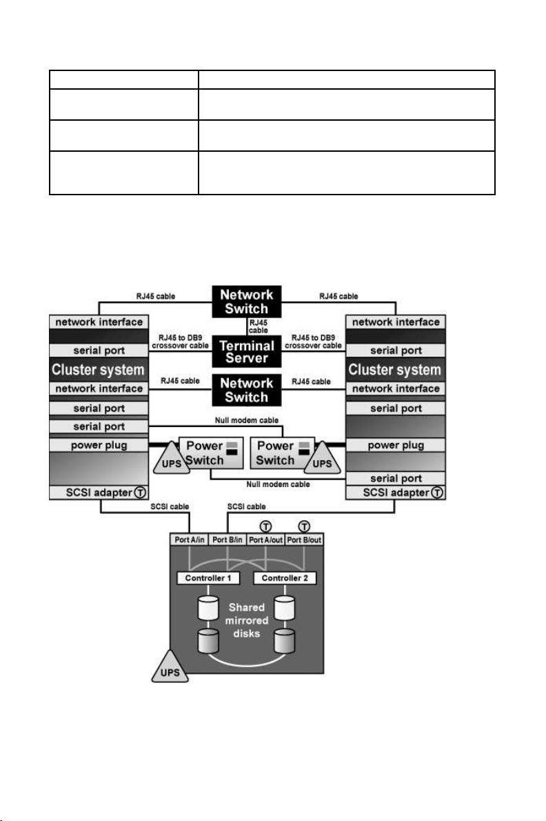
Figure 2-1 shows an example of a no single point of failure hardware configuration that includes the
previously-described hardware, two single-initiator SCSI buses, and power switches to guarantee data
integrity under all error conditions. A "T" enclosed in a circle represents a SCSI terminator.
Figure 2-1. No Single Point of Failure Configuration Example
Cluster hardware configurations can also include other optional hardware components that are common in a computing environment. For example, a cluster can include a network switch or network
hub, which enables the connection of the members to a network. A cluster may also include a console
Page 26

10 Chapter 2. Hardware Installation and Operating System Configuration
switch, which facilitates the management of multiple members and eliminates the need for separate
monitors, mouses, and keyboards for each member.
One type of console switch is a terminal server, which enables connection to serial consoles and
management of many members from one remote location. As a low-cost alternative, you can use a
KVM (keyboard, video, and mouse) switch, which enables multiple members to share one keyboard,
monitor, and mouse. A KVM is suitable for configurations in which access to a graphical user interface
(GUI) to perform system management tasks is preferred.
When choosing a system, be sure that it provides the required PCI slots, network slots, and serial
ports. For example, a no single point of failure configuration requires multiple bonded Ethernet ports.
Refer to Section 2.2.1 Installing the Basic Cluster Hardware for more information.
2.1.3. Choosing the Type of Power Controller
The Red Hat Cluster Manager implementation consists of a generic power management layer and a set
of device-specific modules which accommodate a range of power management types. When selecting
the appropriate type of power controller to deploy in the cluster, it is important to recognize the
implications of specific device types. The following describes the types of supported power switches
followed by a summary table. For a more detailed description of the role a power switch plays to
ensure data integrity, refer to Section 2.4.2 Configuring Power Switches.
Serial-attached and network-attached power switches are separate devices which enable one cluster
member to power cycle another member. They resemble a power plug strip on which individual outlets
can be turned on and off under software control through either a serial or network cable. Networkattached power switches differ from serial-attached in that they connect to cluster members via an
Ethernet hub or switch, rather than direct connection to cluster members. A network-attached power
switch can not be directly attached to a cluster member using a crossover cable, as the power switch
would be unable to power cycle the other members.
Watchdog timers provide a means for failed members to remove themselves from the cluster prior
to another member taking over its services, rather than allowing one cluster member to power cycle
another. The normal operational mode for watchdog timers is that the cluster software must periodically reset a timer prior to its expiration. If the cluster software fails to reset the timer, the watchdog
triggers under the assumption that the member may have hung or otherwise failed. The healthy cluster
member allows a window of time to pass prior to concluding that another cluster member has failed
(by default, this window is 12 seconds). The watchdog timer interval must be less than the duration of
time for one cluster member to conclude that another has failed. In this manner, a healthy member can
assume, prior to taking over services, that the failed cluster member has safely removed itself from
the cluster (by rebooting) and is no longer a risk to data integrity. The underlying watchdog support
is included in the core Linux kernel. Red Hat Cluster Manager utilizes these watchdog features via its
standard APIs and configuration mechanism.
There are two types of watchdog timers: hardware-based and software-based. Hardware-based watchdog timers typically consist of system board components such as the Intel® i810 TCO chipset. This
circuitry has a high degree of independence from the main system CPU. This independence is beneficial in failure scenarios of a true system hang, as in this case it pulls down the system’s reset lead
resulting in a system reboot. Some PCI expansion cards provide watchdog features.
Software-based watchdog timers do not have any dedicated hardware. The implementation is a kernel
thread which is periodically run; if the timer duration has expired, the thread initiates a system reboot.
The vulnerability of the software watchdog timer is that under certain failure scenarios, such as system
hangs while interrupts are blocked, the kernel thread is not called. As a result, in such conditions it
cannot be definitively depended on for data integrity. This can cause the healthy cluster member to
take over services for a hung member which could cause data corruption under certain scenarios.
Finally, administrators can choose not to employ a power controller at all. When a power controller
is not in use, no provision exists for a cluster member to power cycle a failed member. Similarly, the
failed member cannot be guaranteed to reboot itself under all failure conditions.
Page 27

Chapter 2. Hardware Installation and Operating System Configuration 11
Important
Use of a power controller is strongly recommended as part of a production cluster environment.
Configuration of a cluster without a power controller is not supported.
Ultimately, the right type of power controller deployed in a cluster environment depends on the data
integrity requirements weighed against the cost and availability of external power switches.
Table 2-4 summarizes the types of supported power management modules and discusses their advantages and disadvantages individually.
Type Notes Pros Cons
Serial-attached
power switches
(supported for
two-member
clusters only)
Network-attached
power switches
Hardware
Watchdog Timer
Software
Watchdog Timer
Two serial attached
power controllers are
used in a cluster (one per
member)
A single network
attached power
controller is required per
cluster (depending on
the number of
members); however, up
to three are supported
for each cluster member
Affords strong data
integrity guarantees
Offers acceptable data
integrity provisions
Affords strong data
integrity guarantees —
the power controller
itself is not a single
point of failure as there
are two in a cluster
Affords strong data
integrity guarantees and
can be used in clusters
with more than two
members
Obviates the need to
purchase external power
controller hardware
Obviates the need to
purchase external power
controller hardware;
works on any system
Requires purchase of
power controller
hardware and cables;
consumes serial ports;
can only be used in
two-member cluster
Requires purchase of
power controller
hardware — the power
controller itself can
become a single point of
failure (although they
are typically very
reliable devices)
Not all systems include
supported watchdog
hardware
Under some failure
scenarios, the software
watchdog is not
operational, opening a
small vulnerability
window
No power
controller
No power controller
function is in use
Obviates the need to
purchase external power
controller hardware;
Vulnerable to data
corruption under certain
failure scenarios
works on any system
Table 2-4. Power Switches
2.1.4. Cluster Hardware Components
Use the following tables to identify the hardware components required for the cluster configuration.
Table 2-5 includes the hardware required for the cluster members.
Page 28

12 Chapter 2. Hardware Installation and Operating System Configuration
Hardware Quantity Description Required
Cluster
members
eight
(maximum
supported)
Each member must provide enough PCI slots,
network slots, and serial ports for the cluster
hardware configuration. Because disk devices
Yes
must have the same name on each member, it is
recommended that the members have symmetric
I/O subsystems. It is also recommended that the
processor speed and amount of system memory
be adequate for the processes run on the cluster
members. Consult the Red Hat Enterprise Linux
3 Release Notes for specifics. Refer to
Section 2.2.1 Installing the Basic Cluster Hardware
for more information.
Table 2-5. Cluster Member Hardware
Table 2-6 includes several different types of power switches.
A single cluster requires only one type of power switch.
Hardware Quantity Description Required
Serial power
switches
Two In a two-member cluster, use serial power
switches to enable each cluster member to
power-cycle the other member. Refer to
Section 2.4.2 Configuring Power Switches for
more information. Note, cluster members are
configured with either serial power switches
Strongly
recommended
for data
integrity under
all failure
conditions
(supported for two-member clusters only) or
network-attached power switches, but not both.
Null modem
cable
Two Null modem cables connect a serial port on a
cluster member to a serial power switch. This
enables each member to power-cycle the other
Only if using
serial power
switches
member. Some power switches may require
different cables.
Mounting
bracket
One Some power switches support rack mount
configurations and require a separate mounting
bracket.
Only for rack
mounting
power
switches
Network
power switch
One (depends
on member
count)
Network-attached power switches enable each
cluster member to power cycle all others. Refer
to Section 2.4.2 Configuring Power Switches for
more information.
Strongly
recommended
for data
integrity under
all failure
conditions
Watchdog
Timer
One per
member
Watchdog timers cause a failed cluster member
to remove itself from a cluster prior to a healthy
member taking over its services. Refer to
Section 2.4.2 Configuring Power Switches for
more information.
Recommended
for data
integrity on
systems which
provide
integrated
watchdog
hardware
Page 29

Chapter 2. Hardware Installation and Operating System Configuration 13
Table 2-6. Power Switch Hardware Table
Table 2-8 through Table 2-10 show a variety of hardware components for an administrator to choose
from. An individual cluster does not require all of the components listed in these tables.
Hardware Quantity Description Required
Network
interface
One for each
network
Each network connection requires a network
interface installed in a member.
Yes
connection
Network
switch or hub
Network cable One for each
One A network switch or hub allows connection of
multiple members to a network.
A conventional network cable, such as a cable
network
interface
with an RJ45 connector, connects each network
interface to a network switch or a network hub.
No
Yes
Table 2-7. Network Hardware Table
Hardware Quantity Description Required
Host bus
adapter
One per
member
To connect to shared disk storage, install either
a parallel SCSI or a Fibre Channel host bus
Yes
adapter in a PCI slot in each cluster member.
For parallel SCSI, use a low voltage
differential (LVD) host bus adapter. Adapters
have either HD68 or VHDCI connectors.
Host-bus adapter based RAID cards are only
supported if they correctly support multi-host
operation. At the time of publication, there were
no fully tested host-bus adapter based RAID
cards.
External disk
storage
enclosure
At least one Use Fibre Channel or single-initiator parallel
SCSI to connect the cluster members to a
single or dual-controller RAID array. To use
Yes
single-initiator buses, a RAID controller must
have multiple host ports and provide
simultaneous access to all the logical units on
the host ports. To use a dual-controller RAID
array, a logical unit must fail over from one
controller to the other in a way that is
transparent to the OS.
SCSI RAID arrays that provide simultaneous
access to all logical units on the host ports are
recommended.
To ensure symmetry of device IDs and LUNs,
many RAID arrays with dual redundant
controllers must be configured in an
active/passive mode.
Refer to
Section 2.4.4 Configuring Shared Disk Storage
for more information.
Page 30

14 Chapter 2. Hardware Installation and Operating System Configuration
Hardware Quantity Description Required
SCSI cable One per
member
SCSI cables with 68 pins connect each host bus
adapter to a storage enclosure port. Cables have
either HD68 or VHDCI connectors. Cables vary
Only for
parallel SCSI
configurations
based on adapter type.
SCSI
terminator
As required by
hardware
configuration
For a RAID storage enclosure that uses "out"
ports (such as FlashDisk RAID Disk Array) and
is connected to single-initiator SCSI buses,
connect terminators to the "out" ports to
terminate the buses.
Only for
parallel SCSI
configurations
and only as
necessary for
termination
Fibre Channel
hub or switch
One or two A Fibre Channel hub or switch may be required. Only for some
Fibre Channel
configurations
Fibre Channel
cable
As required by
hardware
configuration
A Fibre Channel cable connects a host bus
adapter to a storage enclosure port, a Fibre
Channel hub, or a Fibre Channel switch. If a hub
Only for Fibre
Channel
configurations
or switch is used, additional cables are needed to
connect the hub or switch to the storage adapter
ports.
Table 2-8. Shared Disk Storage Hardware Table
Hardware Quantity Description Required
Network
interface
Two for each
member
Each Ethernet connection requires
a network interface card installed
No
on all cluster members.
Network
crossover cable
One for each
channel
A network crossover cable
connects a network interface on
one member to a network interface
on other cluster members, creating
an Ethernet connection for
Only for a redundant
Ethernet connection (use
of channel-bonded
Ethernet connection is
preferred)
communicating heartbeat.
Table 2-9. Point-To-Point Ethernet Connection Hardware Table
Hardware Quantity Description Required
UPS system One or more Uninterruptible power supply (UPS) systems
protect against downtime if a power outage
occurs. UPS systems are highly recommended
Strongly
recommended
for availability
for cluster operation. Connect the power cables
for the shared storage enclosure and both power
switches to redundant UPS systems. Note, a
UPS system must be able to provide voltage for
an adequate period of time, and should be
connected to its own power circuit.
Table 2-10. UPS System Hardware Table
Page 31

Chapter 2. Hardware Installation and Operating System Configuration 15
Hardware Quantity Description Required
Terminal
server
KVM One A KVM enables multiple members to share one
Table 2-11. Console Switch Hardware Table
One A terminal server enables you to manage many
members from one remote location.
keyboard, monitor, and mouse. Cables for
connecting members to the switch depend on the
type of KVM.
No
No
2.2. Setting Up the Members
After identifying the cluster hardware components described in
Section 2.1 Choosing a Hardware Configuration, set up the basic cluster hardware and connect the
members to the optional console switch and network switch or hub. Follow these steps:
1. In all members, install the required network adapters and host bus adapters. Refer to
Section 2.2.1 Installing the Basic Cluster Hardware for more information about performing
this task.
2. Set up the optional console switch and connect it to each member. Refer to
Section 2.2.2 Setting Up a Console Switch for more information about performing this task.
If a console switch is not used, then connect each member to a console terminal.
3. Set up the optional network switch or hub and use conventional network cables
to connect it to the members and the terminal server (if applicable). Refer to
Section 2.2.3 Setting Up a Network Switch or Hub for more information about performing this
task.
If a network switch or hub is not used, then conventional network cables should be used to
connect each member and the terminal server (if applicable) to a network.
After performing the previous tasks, install Red Hat Enterprise Linux as described in
Section 2.3 Installing and Configuring Red Hat Enterprise Linux.
2.2.1. Installing the Basic Cluster Hardware
Members must provide the CPU processing power and memory required by applications.
In addition, members must be able to accommodate the SCSI or Fibre Channel adapters, network
interfaces, and serial ports that the hardware configuration requires. Systems have a limited number of
pre-installed serial and network ports and PCI expansion slots. Table 2-12 helps determine how much
capacity the member systems employed require.
Cluster Hardware Component Serial
Ports
SCSI or Fibre Channel adapter to shared disk storage One for
Network
Slots
PCI
Slots
each bus
adapter
Page 32

16 Chapter 2. Hardware Installation and Operating System Configuration
Cluster Hardware Component Serial
Ports
Network connection for client access and Ethernet heartbeat
pings
Point-to-point Ethernet connection for 2-node clusters
(optional)
Terminal server connection (optional) One
Table 2-12. Installing the Basic Cluster Hardware
Most systems come with at least one serial port. If a system has graphics display capability, it is
possible to use the serial console port for a power switch connection. To expand your serial port
capacity, use multi-port serial PCI cards. For multiple-member clusters, use a network power switch.
Also, ensure that local system disks are not on the same SCSI bus as the shared disks. For example,
use two-channel SCSI adapters, such as the Adaptec 39160-series cards, and put the internal devices
on one channel and the shared disks on the other channel. Using multiple SCSI cards is also possible.
Refer to the system documentation supplied by the vendor for detailed installation information. Refer
to Appendix D Supplementary Hardware Information for hardware-specific information about using
host bus adapters in a cluster.
Figure 2-2 shows the bulkhead of a sample member and the external cable connections for a typical
cluster configuration.
Network
Slots
One for
each
network
connection
One for
each connection
PCI
Slots
Figure 2-2. Typical External Cabling for a Cluster Member
Page 33

Chapter 2. Hardware Installation and Operating System Configuration 17
2.2.2. Setting Up a Console Switch
Although a console switch is not required for cluster operation, it can be used to facilitate member
management and eliminate the need for separate monitors, mouses, and keyboards for each cluster
member. There are several types of console switches.
For example, a terminal server enables connection to serial consoles and management of many members from a remote location. For a low-cost alternative, use a KVM (keyboard, video, and mouse)
switch, which enables multiple members to share one keyboard, monitor, and mouse. A KVM switch
is suitable for configurations in which GUI access to perform system management tasks is preferred.
Set up the console switch according to the documentation provided by the vendor.
After the console switch has been set up, connect it to each cluster member. The cables used depend
on the type of console switch. For example, a Cyclades terminal server uses RJ45 to DB9 crossover
cables to connect a serial port on each member to the terminal server.
2.2.3. Setting Up a Network Switch or Hub
A network switch or hub, although not required for operating a two-node cluster, can be used to
facilitate cluster and client system network operations. Clusters of more than two members require a
switch or hub.
Set up a network switch or hub according to the documentation provided by the vendor.
After setting up the network switch or hub, connect it to each member by using conventional network
cables. A terminal server, if used, is connected to the network switch or hub through a network cable.
2.3. Installing and Configuring Red Hat Enterprise Linux
After the setup of basic cluster hardware, proceed with installation of Red Hat Enterprise Linux on
each member and ensure that all systems recognize the connected devices. Follow these steps:
1. Install Red Hat Enterprise Linux on all cluster members. Refer to Red Hat Enterprise Linux
Installation Guide for instructions.
In addition, when installing Red Hat Enterprise Linux, it is strongly recommended to do the
following:
• Gather the IP addresses for the members and for the bonded Ethernet ports, before installing
Red Hat Enterprise Linux. Note that the IP addresses for the bonded Ethernet ports can be
private IP addresses, (for example, 10.x.x.x).
• Do not place local file systems (such as /, /etc, /tmp, and /var) on shared disks or on the
same SCSI bus as shared disks. This helps prevent the other cluster members from accidentally mounting these file systems, and also reserves the limited number of SCSI identification
numbers on a bus for cluster disks.
• Place /tmp and /var on different file systems. This may improve member performance.
• When a member boots, be sure that the member detects the disk devices in the same order in
which they were detected during the Red Hat Enterprise Linux installation. If the devices are
not detected in the same order, the member may not boot.
• When using RAID storage configured with Logical Unit Numbers (LUNs) greater than zero,
it is necessary to enable LUN support by adding the following to /etc/modules.conf:
options scsi_mod max_scsi_luns=255
Page 34

18 Chapter 2. Hardware Installation and Operating System Configuration
After modifying modules.conf, it is necessary to rebuild the initial ram disk using
mkinitrd. Refer to the Red Hat Enterprise Linux System Administration Guide for more
information about creating ramdisks using mkinitrd.
2. Reboot the members.
3. When using a terminal server, configure Red Hat Enterprise Linux to send console messages to
the console port.
4. Edit the /etc/hosts file on each cluster member and include the IP addresses used in the cluster or ensure that the addresses are in DNS. Refer to Section 2.3.1 Editing the /etc/hosts File
for more information about performing this task.
5. Decrease the alternate kernel boot timeout limit to reduce boot time for members. Refer to
Section 2.3.2 Decreasing the Kernel Boot Timeout Limit for more information about performing this task.
6. Ensure that no login (or getty) programs are associated with the serial ports that are being
used for the remote power switch connection (if applicable). To perform this task, edit the
/etc/inittab file and use a hash symbol (#) to comment out the entries that correspond
to the serial ports used for the remote power switch. Then, invoke the init q command.
7. Verify that all systems detect all the installed hardware:
• Use the dmesg command to display the console startup messages. Refer to
Section 2.3.3 Displaying Console Startup Messages for more information about performing
this task.
• Use the cat /proc/devices command to display the devices configured in the kernel. Re-
fer to Section 2.3.4 Displaying Devices Configured in the Kernel for more information about
performing this task.
8. Verify that the members can communicate over all the network interfaces by using the ping
command to send test packets from one member to another.
9. If intending to configure Samba services, verify that the required RPM packages for Samba
services are installed.
2.3.1. Editing the /etc/hosts File
The /etc/hosts file contains the IP address-to-hostname translation table. The /etc/hosts file on
each member must contain entries for the following:
• IP addresses and associated hostnames for all cluster members
• IP addresses and associated hostnames for the point-to-point Ethernet heartbeat connections (these
can be private IP addresses)
As an alternative to the /etc/hosts file, naming services such as DNS or NIS can be used to define the host names used by a cluster. However, to limit the number of dependencies and optimize
availability, it is strongly recommended to use the /etc/hosts file to define IP addresses for cluster
network interfaces.
The following is an example of an /etc/hosts file on a member:
127.0.0.1 localhost.localdomain localhost
193.186.1.81 cluster2.example.com cluster2
10.0.0.1 ecluster2.example.com ecluster2
193.186.1.82 cluster3.example.com cluster3
10.0.0.2 ecluster3.example.com ecluster3
Page 35

Chapter 2. Hardware Installation and Operating System Configuration 19
The previous example shows the IP addresses and hostnames for two members (cluster2 and cluster3),
and the private IP addresses and hostnames for the Ethernet interface (ecluster2 and ecluster3) used
for the point-to-point heartbeat connection on each member.
Verify correct formatting of the local host entry in the /etc/hosts file to ensure that it does not
include non-local systems in the entry for the local host. An example of an incorrect local host entry
that includes a non-local system (server1) is shown next:
127.0.0.1 localhost.localdomain localhost server1
An Ethernet connection may not operate properly if the format of the /etc/hosts file is not correct.
Check the /etc/hosts file and correct the file format by removing non-local systems from the local
host entry, if necessary.
Note that each network adapter must be configured with the appropriate IP address and netmask.
The following example shows a portion of the output from the /sbin/ifconfig command on a
cluster member:
eth0 Link encap:Ethernet HWaddr 00:00:BC:11:76:93
eth1 Link encap:Ethernet HWaddr 00:00:BC:11:76:92
inet addr:192.186.1.81 Bcast:192.186.1.245 Mask:255.255.255.0
UP BROADCAST RUNNING MULTICAST MTU:1500 Metric:1
RX packets:65508254 errors:225 dropped:0 overruns:2 frame:0
TX packets:40364135 errors:0 dropped:0 overruns:0 carrier:0
collisions:0 txqueuelen:100
Interrupt:19 Base address:0xfce0
inet addr:10.0.0.1 Bcast:10.0.0.245 Mask:255.255.255.0
UP BROADCAST RUNNING MULTICAST MTU:1500 Metric:1
RX packets:0 errors:0 dropped:0 overruns:0 frame:0
TX packets:0 errors:0 dropped:0 overruns:0 carrier:0
collisions:0 txqueuelen:100
Interrupt:18 Base address:0xfcc0
The previous example shows two network interfaces on a cluster member: eth0 (the network interface
for the member) and eth1 (the network interface for the point-to-point Ethernet connection).
You may also add the IP addresses for the cluster members to your DNS server. Refer to the Red
Hat Enterprise Linux Reference Guide for information on configuring DNS, or consult your network
administrator.
2.3.2. Decreasing the Kernel Boot Timeout Limit
It is possible to reduce the boot time for a member by decreasing the kernel boot timeout limit. During
the Red Hat Enterprise Linux boot sequence, the boot loader allows for specifying an alternate kernel
to boot. The default timeout limit for specifying a kernel is ten seconds.
To modify the kernel boot timeout limit for a member, edit the appropriate files as follows:
When using the GRUB boot loader, the timeout parameter in /boot/grub/grub.conf should be
modified to specify the appropriate number of seconds for the timeout parameter. To set this interval
to 3 seconds, edit the parameter to the following:
timeout = 3
When using the LILO or ELILO boot loaders, edit the /etc/lilo.conf file (on x86 systems) or the
elilo.conf file (on Itanium systems) and specify the desired value (in tenths of a second) for the
timeout parameter. The following example sets the timeout limit to three seconds:
Page 36

20 Chapter 2. Hardware Installation and Operating System Configuration
timeout = 30
To apply any changes made to the /etc/lilo.conf file, invoke the /sbin/lilo command.
On an Itanium system, to apply any changes made to the /boot/efi/efi/redhat/elilo.conf
file, invoke the /sbin/elilo command.
2.3.3. Displaying Console Startup Messages
Use the dmesg command to display the console startup messages. Refer to the dmesg(8) man page
for more information.
The following example of output from the dmesg command shows that two external SCSI buses and
nine disks were detected on the member. (Lines with backslashes display as one line on most screens):
May 22 14:02:10 storage3 kernel: scsi0 : Adaptec AHA274x/284x/294x \
(EISA/VLB/PCI-Fast SCSI) 5.1.28/3.2.4
May 22 14:02:10 storage3 kernel:
May 22 14:02:10 storage3 kernel: scsi1 : Adaptec AHA274x/284x/294x \
May 22 14:02:10 storage3 kernel:
May 22 14:02:10 storage3 kernel: scsi : 2 hosts.
May 22 14:02:11 storage3 kernel: Vendor: SEAGATE Model: ST39236LW Rev: 0004
May 22 14:02:11 storage3 kernel: Detected scsi disk sda at scsi0, channel 0, id 0, lun 0
May 22 14:02:11 storage3 kernel: Vendor: SEAGATE Model: ST318203LC Rev: 0001
May 22 14:02:11 storage3 kernel: Detected scsi disk sdb at scsi1, channel 0, id 0, lun 0
May 22 14:02:11 storage3 kernel: Vendor: SEAGATE Model: ST318203LC Rev: 0001
May 22 14:02:11 storage3 kernel: Detected scsi disk sdc at scsi1, channel 0, id 1, lun 0
May 22 14:02:11 storage3 kernel: Vendor: SEAGATE Model: ST318203LC Rev: 0001
May 22 14:02:11 storage3 kernel: Detected scsi disk sdd at scsi1, channel 0, id 2, lun 0
May 22 14:02:11 storage3 kernel: Vendor: SEAGATE Model: ST318203LC Rev: 0001
May 22 14:02:11 storage3 kernel: Detected scsi disk sde at scsi1, channel 0, id 3, lun 0
May 22 14:02:11 storage3 kernel: Vendor: SEAGATE Model: ST318203LC Rev: 0001
May 22 14:02:11 storage3 kernel: Detected scsi disk sdf at scsi1, channel 0, id 8, lun 0
May 22 14:02:11 storage3 kernel: Vendor: SEAGATE Model: ST318203LC Rev: 0001
May 22 14:02:11 storage3 kernel: Detected scsi disk sdg at scsi1, channel 0, id 9, lun 0
May 22 14:02:11 storage3 kernel: Vendor: SEAGATE Model: ST318203LC Rev: 0001
May 22 14:02:11 storage3 kernel: Detected scsi disk sdh at scsi1, channel 0, id 10, lun 0
May 22 14:02:11 storage3 kernel: Vendor: SEAGATE Model: ST318203LC Rev: 0001
May 22 14:02:11 storage3 kernel: Detected scsi disk sdi at scsi1, channel 0, id 11, lun 0
May 22 14:02:11 storage3 kernel: Vendor: Dell Model: 8 BAY U2W CU Rev: 0205
May 22 14:02:11 storage3 kernel: Type: Processor \
May 22 14:02:11 storage3 kernel: scsi1 : channel 0 target 15 lun 1 request sense \
May 22 14:02:11 storage3 kernel: SCSI bus is being reset for host 1 channel 0.
May 22 14:02:11 storage3 kernel: scsi : detected 9 SCSI disks total.
The following example of the dmesg command output shows that a quad Ethernet card was detected
on the member:
May 22 14:02:11 storage3 kernel: 3c59x.c:v0.99H 11/17/98 Donald Becker
May 22 14:02:11 storage3 kernel: tulip.c:v0.91g-ppc 7/16/99 becker@cesdis.gsfc.nasa.gov
May 22 14:02:11 storage3 kernel: eth0: Digital DS21140 Tulip rev 34 at 0x9800, \
May 22 14:02:12 storage3 kernel: eth1: Digital DS21140 Tulip rev 34 at 0x9400, \
May 22 14:02:12 storage3 kernel: eth2: Digital DS21140 Tulip rev 34 at 0x9000, \
May 22 14:02:12 storage3 kernel: eth3: Digital DS21140 Tulip rev 34 at 0x8800, \
(EISA/VLB/PCI-Fast SCSI) 5.1.28/3.2.4
ANSI SCSI revision: 03
failed, performing reset.
00:00:BC:11:76:93, IRQ 5.
00:00:BC:11:76:92, IRQ 9.
00:00:BC:11:76:91, IRQ 11.
Page 37

Chapter 2. Hardware Installation and Operating System Configuration 21
00:00:BC:11:76:90, IRQ 10.
2.3.4. Displaying Devices Configured in the Kernel
To be sure that the installed devices, including serial and network interfaces, are configured in the kernel, use the cat /proc/devices command on each member. Use this command to also determine
if there is raw device support installed on the member. For example:
Character devices:
1 mem
2 pty
3 ttyp
4 ttyS
5 cua
7 vcs
10 misc
19 ttyC
20 cub
128 ptm
136 pts
162 raw
Block devices:
2 fd
3 ide0
8 sd
65 sd
The previous example shows:
• Onboard serial ports (ttyS)
• Serial expansion card (ttyC)
• Raw devices (raw)
• SCSI devices (sd)
2.4. Setting Up and Connecting the Cluster Hardware
After installing Red Hat Enterprise Linux, set up the cluster hardware components and verify
the installation to ensure that the members recognize all the connected devices. Note that
the exact steps for setting up the hardware depend on the type of configuration. Refer to
Section 2.1 Choosing a Hardware Configuration for more information about cluster configurations.
To set up the cluster hardware, follow these steps:
1. Shut down the members and disconnect them from their power source.
2. Set up the bonded Ethernet channels, if applicable. Refer to
Section 2.4.1 Configuring Ethernet Channel Bonding for more information.
3. When using power switches, set up the switches and connect each member to a power switch.
Refer to Section 2.4.2 Configuring Power Switches for more information.
Page 38

22 Chapter 2. Hardware Installation and Operating System Configuration
In addition, it is recommended to connect each power switch (or each member’s
power cord if not using power switches) to a different UPS system. Refer to
Section 2.4.3 Configuring UPS Systems for information about using optional UPS systems.
4. Set up the shared disk storage according to the vendor instructions and connect the members
to the external storage enclosure. Refer to Section 2.4.4 Configuring Shared Disk Storage for
more information about performing this task.
In addition, it is recommended to connect the storage enclosure to redundant UPS systems.
Refer to Section 2.4.3 Configuring UPS Systems for more information about using optional UPS
systems.
5. Turn on power to the hardware, and boot each cluster member. During the boot-up process, enter
the BIOS utility to modify the member setup, as follows:
• Ensure that the SCSI identification number used by the HBA is unique for the SCSI bus it
is attached to. Refer to Section D.5 SCSI Identification Numbers for more information about
performing this task.
• Enable or disable the onboard termination for each host bus adapter, as required by the
storage configuration. Refer to Section 2.4.4 Configuring Shared Disk Storage and
Section D.3 SCSI Bus Termination for more information about performing this task.
• Enable the member to automatically boot when it is powered on.
6. Exit from the BIOS utility, and continue to boot each member. Examine the startup messages
to verify that the Red Hat Enterprise Linux kernel has been configured and can recognize the
full set of shared disks. Use the dmesg command to display console startup messages. Refer to Section 2.3.3 Displaying Console Startup Messages for more information about using the
dmesg command.
7. Verify that the members can communicate over each point-to-point Ethernet connection by using the ping command to send packets over each network interface.
8. Set up the shared cluster partitions on the shared disk storage. Refer to
Section 2.4.4.3 Configuring Shared Cluster Partitions for more information about performing
this task.
2.4.1. Configuring Ethernet Channel Bonding
Ethernet channel bonding in a no-single-point-of-failure cluster system allows for a fault tolerant
network connection by combining two Ethernet devices into one virtual device. The resulting channel
bonded interface ensures that in the event that one Ethernet device fails, the other device will become
active. This type of channel bonding, called an active-backup policy allows connection of both bonded
devices to one switch or can allow each Ethernet device to be connected to separate hubs or switches,
which eliminates the single point of failure in the network hub/switch.
Channel bonding requires each cluster member to have two Ethernet devices installed. When it is
loaded, the bonding module uses the MAC address of the first enslaved network device and assigns
that MAC address to the other network device if the first device fails link detection.
To configure two network devices for channel bonding, perform the following:
1. Create a bonding devices in /etc/modules.conf. For example:
alias bond0 bonding
options bonding miimon=100 mode=1
This loads the bonding device with the bond0 interface name, as well as passes options to
the bonding driver to configure it as an active-backup master device for the enslaved network
interfaces.
Page 39

Chapter 2. Hardware Installation and Operating System Configuration 23
2. Edit the /etc/sysconfig/network-scripts/ifcfg-ethX configuration file for both eth0
and eth1 so that the files show identical contents. For example:
DEVICE=ethX
USERCTL=no
ONBOOT=yes
MASTER=bond0
SLAVE=yes
BOOTPROTO=none
This will enslave ethX (replace X with the assigned number of the Ethernet devices) to the
bond0 master device.
3. Create a network script for the bonding device (for example,
/etc/sysconfig/network-scripts/ifcfg-bond0), which would appear like the
following example:
DEVICE=bond0
USERCTL=no
ONBOOT=yes
BROADCAST=192.168.1.255
NETWORK=192.168.1.0
NETMASK=255.255.255.0
GATEWAY=192.168.1.1
IPADDR=192.168.1.10
4. Reboot the system for the changes to take effect. Alternatively, manually load the bonding device and restart the network. For example:
/sbin/insmod /lib/modules/‘uname -r‘/kernel/drivers/net/bonding/bonding.o \
miimon=100 mode=1
/sbin/service network restart
For more information about channel bonding, refer to the high-availability section of the Linux Ethernet Bonding Driver Mini-Howto, available in:
/usr/src/linux-2.4/Documentation/networkin g/bonding.txt
Note
You must have the kernel-source package installed in order to view the Linux Ethernet Bonding
Driver Mini-Howto.
2.4.2. Configuring Power Switches
Power switches enable a member to power-cycle another member before restarting its services as part
of the failover process. The ability to remotely disable a member ensures data integrity is maintained
under any failure condition. It is recommended that production environments use power switches
or watchdog timers in the cluster configuration. Only development (test) environments should use a
configuration without power switches. Refer to Section 2.1.3 Choosing the Type of Power Controller
for a description of the various types of power switches. Note that within this section, the general term
"power switch" also includes watchdog timers.
In a cluster configuration that uses physical power switches, each member’s power cable is connected
to a power switch through either a serial or network connection (depending on switch type). When
failover occurs, a member can use this connection to power-cycle another member before restarting
its services.
Page 40

24 Chapter 2. Hardware Installation and Operating System Configuration
Power switches protect against data corruption if an unresponsive (or hanging) member becomes
responsive after its services have failed over, and issues I/O to a disk that is also receiving I/O from
another member. In addition, if a quorum daemon fails on a member, the member is no longer able to
monitor the shared cluster partitions. If power switches or watchdog timers are not used in the cluster,
then this error condition may result in services being run on more than one member, which can cause
data corruption and possibly system crashes.
It is strongly recommended to use power switches in a cluster. However, administrators who are aware
of the risks may choose to set up a cluster without power switches.
A member may hang for a few seconds if it is swapping or has a high system workload. For this reason,
adequate time is allowed prior to concluding another member has failed (typically 15 seconds).
If a member determines that a hung member is down, and power switches are used in the cluster,
that member power-cycles the hung member before restarting its services. Clusters configured to use
watchdog timers self-reboot under most system hangs. This causes the hung member to reboot in a
clean state and prevent it from issuing I/O and corrupting service data.
Hung members reboot themselves either due to a watchdog firing, failure to send heartbeat packets,
or — in the case a member has no physical power switch — loss of quorum status.
Hung members may be rebooted by other members if they are attached to a power switch. If the hung
member never becomes responsive and no power switches are in use, then a manual reboot is required.
When used, power switches must be set up according to the vendor instructions. However,
some cluster-specific tasks may be required to use a power switch in the cluster. Refer to
Section D.1 Setting Up Power Controllers for detailed information on power switches (including
information about watchdog timers). Be sure to take note of any caveats or functional attributes
of specific power switches. Note that the cluster-specific information provided in this manual
supersedes the vendor information.
When cabling power switches, take special care to ensure that each cable is plugged into the appropriate outlet. This is crucial because there is no independent means for the software to verify correct
cabling. Failure to cable correctly can lead to an incorrect member being power cycled, or for one
member to inappropriately conclude that it has successfully power cycled another cluster member.
After setting up the power switches, perform these tasks to connect them to the members:
1. Connect the power cable for each member to a power switch.
2. Connect each member to the power switch. The cable used for the connection depends on the
type of power switch. Serial-attached power switches use null modem cables, while a networkattached power switches require an Ethernet patch cable.
3. Connect the power cable for each power switch to a power source. It is recommended to connect
each power switch to a different UPS system. Refer to Section 2.4.3 Configuring UPS Systems
for more information.
After the installation of the cluster software, test the power switches to ensure that
each member can power-cycle the other member before starting the cluster. Refer to
Section 3.11.2 Testing the Power Switches for information.
2.4.3. Configuring UPS Systems
Uninterruptible power supplies (UPS) provide a highly-available source of power. Ideally, a redundant
solution should be used that incorporates multiple UPS systems (one per server). For maximal faulttolerance, it is possible to incorporate two UPS systems per server as well as APC Automatic Transfer
Switches to manage the power and shutdown management of the server. Both solutions are solely
dependent on the level of availability desired.
Page 41

Chapter 2. Hardware Installation and Operating System Configuration 25
It is not recommended to use a single UPS infrastructure as the sole source of power for the cluster. A
UPS solution dedicated to the cluster is more flexible in terms of manageability and availability.
A complete UPS system must be able to provide adequate voltage and current for a prolonged period
of time. While there is no single UPS to fit every power requirement, a solution can be tailored to fit
a particular configuration.
If the cluster disk storage subsystem has two power supplies with separate power cords, set up
two UPS systems, and connect one power switch (or one member’s power cord if not using power
switches) and one of the storage subsystem’s power cords to each UPS system. A redundant UPS
system configuration is shown in Figure 2-3.
Figure 2-3. Redundant UPS System Configuration
An alternative redundant power configuration is to connect the power switches (or the members’
power cords) and the disk storage subsystem to the same UPS system. This is the most cost-effective
configuration, and provides some protection against power failure. However, if a power outage occurs,
the single UPS system becomes a possible single point of failure. In addition, one UPS system may
not be able to provide enough power to all the attached devices for an adequate amount of time. A
single UPS system configuration is shown in Figure 2-4.
Figure 2-4. Single UPS System Configuration
Page 42

26 Chapter 2. Hardware Installation and Operating System Configuration
Many vendor-supplied UPS systems include Red Hat Enterprise Linux applications that monitor the
operational status of the UPS system through a serial port connection. If the battery power is
low, the monitoring software initiates a clean system shutdown. As this occurs, the cluster
software is properly stopped, because it is controlled by a SysV runlevel script (for example,
/etc/rc.d/init.d/clumanager).
Refer to the UPS documentation supplied by the vendor for detailed installation information.
2.4.4. Configuring Shared Disk Storage
In a cluster, shared disk storage is used to hold service data and two partitions (primary and shadow)
that store cluster state information. Because this storage must be available to all members, it cannot be
located on disks that depend on the availability of any one member. Refer to the vendor documentation
for detailed product and installation information.
There are some factors to consider when setting up shared disk storage in a cluster:
• External RAID
It is strongly recommended to use use RAID 1 (mirroring) to make service data and the shared cluster partitions highly available. Optionally, parity RAID can also be employed for high-availability.
Do not use RAID 0 (striping) alone for shared partitions because this reduces storage availability.
• Multi-initiator SCSI configurations
Multi-initiator SCSI configurations are not supported due to the difficulty in obtaining proper bus
termination.
• The Red Hat Enterprise Linux device name for each shared storage device must be the same on
each member. For example, a device named /dev/sdc on one member must be named /dev/sdc
on the other cluster members. Using identical hardware for all members usually ensures that these
devices are named the same.
• A disk partition can be used by only one cluster service.
• Do not include any file systems used in a cluster service in the member’s local /etc/fstab files,
because the cluster software must control the mounting and unmounting of service file systems.
• For optimal performance of shared file systems, make sure to specify a 4 KB block size
with the -b option to mke2fs. A smaller block size can cause long fsck times. Refer to
Section 2.4.4.6 Creating File Systems.
The following list details parallel SCSI requirements, and must be adhered to when parallel SCSI
buses are employed in a cluster environment:
• SCSI buses must be terminated at each end, and must adhere to length and hot plugging restrictions.
• Devices (disks, host bus adapters, and RAID controllers) on a SCSI bus must have a unique SCSI
identification number.
Refer to Section D.2 SCSI Bus Configuration Requirements for more information.
It is strongly recommended to connect the storage enclosure to redundant UPS systems for a highlyavailable source of power. Refer to Section 2.4.3 Configuring UPS Systems for more information.
Refer to Section 2.4.4.1 Setting Up a Single-initiator SCSI Bus and
Section 2.4.4.2 Setting Up a Fibre Channel Interconnect for more information about configuring
shared storage.
After setting up the shared disk storage hardware, partition the disks and then either create file
systems or raw devices on the partitions. Two raw devices must be created for the primary and the
shadow shared cluster partitions. Refer to Section 2.4.4.3 Configuring Shared Cluster Partitions,
Page 43

Chapter 2. Hardware Installation and Operating System Configuration 27
Section 2.4.4.4 Partitioning Disks, Section 2.4.4.5 Creating Raw Devices, and
Section 2.4.4.6 Creating File Systems for more information.
2.4.4.1. Setting Up a Single-initiator SCSI Bus
A single-initiator SCSI bus has only one member connected to it, and provides host isolation and better
performance than a multi-initiator bus. Single-initiator buses ensure that each member is protected
from disruptions due to the workload, initialization, or repair of the other members.
When using a single- or dual-controller RAID array that has multiple host ports and provides simultaneous access to all the shared logical units from the host ports on the storage enclosure, the setup
of the single-initiator SCSI buses to connect each cluster member to the RAID array is possible. If
a logical unit can fail over from one controller to the other, the process must be transparent to the
operating system. Note that some RAID controllers restrict a set of disks to a specific controller or
port. In this case, single-initiator bus setups are not possible.
A single-initiator bus must adhere to the requirements described in
Section D.2 SCSI Bus Configuration Requirements.
To set up a single-initiator SCSI bus configuration, the following is required:
• Enable the on-board termination for each host bus adapter.
• Enable the termination for each RAID controller.
• Use the appropriate SCSI cable to connect each host bus adapter to the storage enclosure.
Setting host bus adapter termination is usually done in the adapter BIOS utility during member boot.
To set RAID controller termination, refer to the vendor documentation. Figure 2-5 shows a configuration that uses two single-initiator SCSI buses.
Figure 2-5. Single-initiator SCSI Bus Configuration
Figure 2-6 shows the termination in a single-controller RAID array connected to two single-initiator
SCSI buses.
Page 44

28 Chapter 2. Hardware Installation and Operating System Configuration
Figure 2-6. Single-controller RAID Array Connected to Single-initiator SCSI Buses
Figure 2-7 shows the termination in a dual-controller RAID array connected to two single-initiator
SCSI buses.
Figure 2-7. Dual-controller RAID Array Connected to Single-initiator SCSI Buses
2.4.4.2. Setting Up a Fibre Channel Interconnect
Fibre Channel can be used in either single-initiator or multi-initiator configurations.
A single-initiator Fibre Channel interconnect has only one member connected to it. This may provide
better host isolation and better performance than a multi-initiator bus. Single-initiator interconnects
ensure that each member is protected from disruptions due to the workload, initialization, or repair of
the other member.
If employing a RAID array that has multiple host ports, and the RAID array provides simultaneous
access to all the shared logical units from the host ports on the storage enclosure, set up single-initiator
Fibre Channel interconnects to connect each member to the RAID array. If a logical unit can fail over
from one controller to the other, the process must be transparent to the operating system.
Figure 2-8 shows a single-controller RAID array with two host ports and the host bus adapters connected directly to the RAID controller, without using Fibre Channel hubs or switches. When using
this type of single-initiator Fibre Channel connection, your RAID controller must have a separate host
port for each cluster member.
Page 45

Chapter 2. Hardware Installation and Operating System Configuration 29
Figure 2-8. Single-controller RAID Array Connected to Single-initiator Fibre Channel Interconnects
The external RAID array must have a separate SCSI channel for each cluster member. In clusters with
more than two members, connect each member to a different SCSI channel on the RAID array, using
a single-initiator SCSI bus as shown in Figure 2-8.
To connect multiple cluster members to the same host port on the RAID array, use an FC hub or
switch. In this case, each HBA is connected to the hub or switch, and the hub or switch is connected
to a host port on the RAID controller.
A Fibre Channel hub or switch is also required with a dual-controller RAID array with two host ports
on each controller. This configuration is shown in Figure 2-9. Additional cluster members may be
connected to either Fibre Channel hub or switch shown in the diagram. Some RAID arrays include a
built-in hub so that each host port is already connected to each of the internal RAID controllers. In
this case, an additional external hub or switch may not be needed.
Page 46

30 Chapter 2. Hardware Installation and Operating System Configuration
Figure 2-9. Dual-controller RAID Array Connected to Single-initiator Fibre Channel Interconnects
2.4.4.3. Configuring Shared Cluster Partitions
Two raw devices on shared disk storage must be created for the primary shared partition and the
shadow shared partition. Each shared partition must have a minimum size of 10 MB. The amount of
data in a shared partition is constant; it does not increase or decrease over time.
The shared partitions are used to hold cluster state information, including the following:
• Cluster lock states
• Service states
• Configuration information
Periodically, each member writes the state of its services to shared storage. In addition, the shared
partitions contain a version of the cluster configuration file. This ensures that each member has a
common view of the cluster configuration.
If the primary shared partition is corrupted, the cluster members read the information from the shadow
(or backup) shared partition and simultaneously repair the primary partition. Data consistency is maintained through checksums, and any inconsistencies between the partitions are automatically corrected.
If a member is unable to write to both shared partitions at startup time, it is not allowed to join
the cluster. In addition, if an active member can no longer write to both shared partitions, the member
removes itself from the cluster by rebooting (and may be remotely power cycled by a healthy member).
The following are shared partition requirements:
• Both partitions must have a minimum size of 10 MB.
• Shared partitions must be raw devices. They cannot contain file systems.
• Shared partitions can be used only for cluster state and configuration information.
The following are recommended guidelines for configuring the shared partitions:
Page 47

Chapter 2. Hardware Installation and Operating System Configuration 31
• It is strongly recommended to set up a RAID subsystem for shared storage, and use RAID 1 (mirror-
ing) to make the logical unit that contains the shared partitions highly available. Optionally, parity
RAID can be used for high availability. Do not use RAID 0 (striping) alone for shared partitions.
• Place both shared partitions on the same RAID set, or on the same disk if RAID is not employed,
because both shared partitions must be available for the cluster to run.
• Do not put the shared partitions on a disk that contains heavily-accessed service data. If possible,
locate the shared partitions on disks that contain service data that is rarely accessed.
Refer to Section 2.4.4.4 Partitioning Disks and Section 2.4.4.5 Creating Raw Devices for more information about setting up the shared partitions.
Refer to Section 3.5 Editing the rawdevices File for information about editing the rawdevices file
to bind the raw character devices to the block devices each time the members boot.
2.4.4.4. Partitioning Disks
After shared disk storage hardware has been set up, partition the disks so they can be used
in the cluster. Then, create file systems or raw devices on the partitions. For example, two
raw devices must be created for the shared partitions using the guidelines described in
Section 2.4.4.3 Configuring Shared Cluster Partitions.
Use parted to modify a disk partition table and divide the disk into partitions. While in parted, use
the p to display the partition table and the mkpart command to create new partitions. The following
example shows how to use parted to create a partition on disk:
• Invoke parted from the shell using the command parted and specifying an available shared disk
device. At the (parted) prompt, use the p to display the current partition table. The output should
be similar to the following:
Disk geometry for /dev/sda: 0.000-4340.294 megabytes
Disk label type: msdos
Minor Start End Type Filesystem Flags
• Decide on how large of a partition is required. Create a partition of this size using the mkpart
command in parted. Although the mkpart does not create a file system, it normally requires a file
system type at partition creation time. parted uses a range on the disk to determine partition size;
the size is the space between the end and the beginning of the given range. The following example
shows how to create two partitions of 20 MB each on an empty disk.
(parted) mkpart primary ext3 0 20
(parted) mkpart primary ext3 20 40
(parted) p
Disk geometry for /dev/sda: 0.000-4340.294 megabytes
Disk label type: msdos
Minor Start End Type Filesystem Flags
1 0.030 21.342 primary
2 21.343 38.417 primary
• When more than four partitions are required on a single disk, it is necessary to create an extended
partition. If an extended partition is required, the mkpart also performs this task. In this case, it is
not necessary to specify a file system type.
Note
Only one extended partition may be created, and the extended partition must be one of the four
primary partitions.
(parted) mkpart extended 40 2000
(parted) p
Page 48

32 Chapter 2. Hardware Installation and Operating System Configuration
Disk geometry for /dev/sda: 0.000-4340.294 megabytes
Disk label type: msdos
Minor Start End Type Filesystem Flags
1 0.030 21.342 primary
2 21.343 38.417 primary
3 38.417 2001.952 extended
• An extended partition allows the creation of logical partitionsinside of it. The following example
shows the division of the extended partition into two logical partitions.
(parted) mkpart logical ext3 40 1000
(parted) p
Disk geometry for /dev/sda: 0.000-4340.294 megabytes
Disk label type: msdos
Minor Start End Type Filesystem Flags
1 0.030 21.342 primary
2 21.343 38.417 primary
3 38.417 2001.952 extended
5 38.447 998.841 logical
(parted) mkpart logical ext3 1000 2000
(parted) p
Disk geometry for /dev/sda: 0.000-4340.294 megabytes
Disk label type: msdos
Minor Start End Type Filesystem Flags
1 0.030 21.342 primary
2 21.343 38.417 primary
3 38.417 2001.952 extended
5 38.447 998.841 logical
6 998.872 2001.952 logical
• A partition may be removed using parted’s rm command. For example:
(parted) rm 1
(parted) p
Disk geometry for /dev/sda: 0.000-4340.294 megabytes
Disk label type: msdos
Minor Start End Type Filesystem Flags
2 21.343 38.417 primary
3 38.417 2001.952 extended
5 38.447 998.841 logical
6 998.872 2001.952 logical
• After all required partitions have been created, exit parted using the quit command. If a
partition was added, removed, or changed while both members are powered on and connected to
the shared storage, reboot the other member for it to recognize the modifications. After
partitioning a disk, format the partition for use in the cluster. For example, create the file systems
or raw devices for shared partitions. Refer to Section 2.4.4.5 Creating Raw Devices and
Section 2.4.4.6 Creating File Systems for more information.
For basic information on partitioning hard disks at installation time, refer to the Red Hat Enterprise
Linux Installation Guide.
2.4.4.5. Creating Raw Devices
After partitioning the shared storage disks, create raw devices on the partitions. File systems are block
devices (for example, /dev/sda1) that cache recently-used data in memory to improve performance.
Raw devices do not utilize system memory for caching. Refer to Section 2.4.4.6 Creating File Systems
for more information.
Red Hat Enterprise Linux supports raw character devices that are not hard-coded against specific
block devices. Instead, Red Hat Enterprise Linux uses a character major number (currently 162) to
implement a series of unbound raw devices in the /dev/raw/ directory. Any block device can have a
character raw device front-end, even if the block device is loaded later at run time.
Page 49

Chapter 2. Hardware Installation and Operating System Configuration 33
To create a raw device, edit the /etc/sysconfig/rawdevices file to bind a raw character device
to the appropriate block device to enable the raw device to be opened, read, and written.
Shared partitions and some database applications require raw devices, because these applications perform their own buffer caching for performance purposes. Shared partitions cannot contain file systems
because if state data was cached in system memory, the members would not have a consistent view of
the state data.
Raw character devices must be bound to block devices each time a member boots. To ensure that
this occurs, edit the /etc/sysconfig/rawdevices file and specify the shared partition bindings.
If using a raw device in a cluster service, use this file to bind the devices at boot time. Refer to
Section 3.5 Editing the rawdevices File for more information.
After editing /etc/sysconfig/rawdevices, the changes take effect either by rebooting or by execute the following command:
service rawdevices restart
Query all the raw devices by using the command raw -aq. The output should be similar to the
following:
/dev/raw/raw1 bound to major 8, minor 17
/dev/raw/raw2 bound to major 8, minor 18
Note that, for raw devices, no cache coherency exists between the raw device and the block device. In
addition, requests must be 512-byte aligned both in memory and on disk. For example, the standard
dd command cannot be used with raw devices because the memory buffer that the command passes
to the write system call is not aligned on a 512-byte boundary.
For more information on using the raw command, refer to the raw(8) man page.
Note
The same raw device names (for example, /dev/raw/raw1 and /dev/raw/raw2) must be used on
all cluster members.
2.4.4.6. Creating File Systems
Use the mkfs command to create an ext3 file system. For example:
mke2fs -j -b 4096 /dev/sde3
For optimal performance of shared file systems, make sure to specify a 4 KB block size with the -b
option to mke2fs. A smaller block size can cause long fsck times.
Page 50

34 Chapter 2. Hardware Installation and Operating System Configuration
Page 51

Chapter 3.
Cluster Configuration
After installing and configuring the cluster hardware, the cluster system software and cluster configuration software can be installed.
3.1. Installing the Red Hat Cluster Suite Packages
The clumanager and redhat-config-cluster packages are required to configure the Red Hat
Cluster Manager. Perform the following instructions to install the Red Hat Cluster Suite on your Red
Hat Enterprise Linux system.
3.1.1. Installation with the Package Management Tool
1. Insert the Red Hat Cluster Suite CD in your CD-ROM drive. If you are using a graphical desktop, the CD will automatically run the Package Management Tool. Click Forward to continue.
Figure 3-1. Package Management Tool
2. Check the box for the Red Hat Cluster Suite, and click the Details link to the package descriptions.
Page 52

36 Chapter 3. Cluster Configuration
Figure 3-2. Choosing Package Group
3. While viewing the package group details, check the box next to the packages to install. Click
Close when finished.
Figure 3-3. Choosing Packages for Installation
4. The Package Management Tool shows an overview of the packages to be installed. Click
Forward to install the packages.
5. When the installation is complete, click Finish to exit the Package Management Tool.
3.1.2. Installation with rpm
If you are not using a graphical desktop environment, you can install the packages manually using the
rpm utility at a shell prompt.
Page 53

Chapter 3. Cluster Configuration 37
Insert the Red Hat Cluster Suite CD into the CD-ROM drive. Log into a shell prompt, change to
the RedHat/RPMS/ directory on the CD, and type the following commands as root (replacing
<version> and <arch> with the version and architecture of the packages to install):
rpm --Uvh clumanager-<version>.<arch>.rpm
rpm --Uvh redhat-config-cluster-<version >.noarch.rpm
3.2. Installation Notes for Red Hat Enterprise Linux 2.1 Users
Warning
Make sure the cluster service is not running on any members before performing the following procedure.
If you are currently running cluster services on Red Hat Enterprise Linux 2.1 and you want to install
Red Hat Enterprise Linux 3 on your system while preserving your cluster configuration, perform the
following steps on the Red Hat Enterprise Linux 2.1 system to backup the cluster configuration before
installing Red Hat Enterprise Linux 3:
1. Stop the cluster service by invoking the command service cluster stop on all cluster
members.
2. Remove the cluster database file (/etc/cluster.conf) from all members, saving a copy with
a different name (for example, /etc/cluster.conf.sav) to a separate running system or
portable storage such as a diskette.
3. Reinstall the Red Hat Enterprise Linux 2.1 system with Red Hat Enterprise Linux 3 on all
members.
4. Install the Red Hat Cluster Suite using the method described in
Section 3.1 Installing the Red Hat Cluster Suite Packages.
5. On all members, install the applications to be managed as services by the cluster software.
6. Restore the cluster database file you saved in step 2 to one member, naming the file
/etc/cluster.conf.
7. Invoke the /usr/sbin/cluster-convert command to convert the /etc/cluster.conf to
/etc/cluster.xml.
8. Configure shared storage on the cluster member by running /usr/sbin/shutil -i which
initializes the shared storage. Then run /usr/sbin/shutil -s /etc/cluster.xml to read
the shared storage information from the file and write it to the shared state.
9. Start the cluster service on this member using the command /sbin/service clumanager
start.
10. Copy the /etc/cluster.xml file to the other member using the scp command.
11. Start the cluster service on the other members.
Page 54

38 Chapter 3. Cluster Configuration
3.3. The Cluster Configuration Tool
Red Hat Cluster Manager consists of the following RPM packages:
• clumanager — This package consists of the software that is responsible for cluster operation
(including the cluster daemons).
• redhat-config-cluster — This package contains the Cluster Configuration Tool and the
Cluster Status Tool, which allow for the configuration of the cluster and the display of the current
status of the cluster and its members and services.
You can use either of the following methods to access the Cluster Configuration Tool:
• Select Main Menu => System Settings => Server Settings => Cluster.
• At a shell prompt, type the redhat-config-cluster command.
The first time that the application is started, the Cluster Configuration Tool is displayed. After you
complete the cluster configuration, the command starts the Cluster Status Tool by default. To access
the Cluster Configuration Tool from the Cluster Status Tool, select Cluster => Configure.
Figure 3-4. The Cluster Configuration Tool
The following tabbed sections are available within the Cluster Configuration Tool:
• Members — Use this section to add members to the cluster and optionally configure a power
controller connection for any given member.
• Failover Domains — Use this section to establish one or more subsets of the cluster members for
specifying which members are eligible to run a service in the event of a system failure. (Note that
the use of failover domains is optional.)
• Services — Use this section to configure one or more services to be managed by the cluster. As you
specify an application service, the relationship between the service and its IP address, device special file, mount point, and NFS exports is represented by a hierarchical structure. The parent-child
relationships in the Cluster Configuration Tool reflect the organization of the service information
in the /etc/cluster.xml file.
Page 55

Chapter 3. Cluster Configuration 39
Warning
Do not manually edit the contents of the /etc/cluster.xml file.
Do not simultaneously run the Cluster Configuration Tool on multiple members. (It is permissible
to run the Cluster Status Tool on more than one member at a time.)
The Cluster Configuration Tool stores information about the cluster service and daemons, cluster
members, and cluster services in the /etc/cluster.xml configuration file. The cluster configuration
file is created the first time the Cluster Configuration Tool is started.
Save the configuration at any point (using File => Save) while running the Cluster Configuration
Tool. When File => Quit is selected, it prompts you to save changes if any unsaved changes to the
configuration are detected.
Note
When you save the cluster configuration for the first time using the Cluster Configuration Tool and
exit the application, the next time you the cluster (either by choosing Main Menu => System Set-
tings => Server Settings => Cluster or by running redhat-config-cluster from a shell prompt)
the Cluster Status Tool will display by default. The Cluster Status Tool displays the status of the
cluster service, cluster members, and application services, and shows statistics concerning service
operation. If you need to further configure the cluster system, choose Cluster => Configure from the
Cluster Status Tool menu.
The Cluster Configuration Tool) is used to configure cluster members, services, and cluster daemons. The Cluster Status Tool is used to monitor, start and stop the cluster members and services
on particular members, and move an application service to another member.
The Cluster Configuration Tool uses a hierarchical tree structure to show relationships between
components in the cluster configuration. A triangular icon to the left of a component name indicates
that the component has children. To expand or collapse the portion of the tree below a component,
click the triangle icon.
Figure 3-5. Cluster Configuration Tool
Page 56

40 Chapter 3. Cluster Configuration
To display the properties of a component, select the component and click Properties. As a shortcut,
you can display the properties of a component by double-clicking on the component name.
To view or modify the properties of the cluster daemons, choose Cluster => Daemon Properties.
3.4. Configuring the Cluster Software
Before describing the steps to configure the cluster software, the hierarchical structure of cluster members and services needs to be considered. Cluster members and services can be thought of in terms of
a parent/child tree structure, as shown in Figure 3-6.
Figure 3-6. Cluster Configuration Structure
Each member can have power controller children. Each service can have IP address children. Each
Service can also have device children. Each device can have NFS export directory children. Each NFS
export directory can have client children. This structure is reflected in the /etc/cluster.xml file
syntax.
The steps to configure the cluster software consist of the following:
1. Edit the /etc/sysconfig/rawdevices file on all cluster members and specify
the raw device special files and character devices for the primary and backup shared
partitions as described in Section 2.4.4.3 Configuring Shared Cluster Partitions and
Section 3.5 Editing the rawdevices File.
2. Run the Cluster Configuration Tool on one cluster member.
3. Enter a name for the cluster in the Cluster Name field. The name should be descriptive enough
to distinguish it from other clusters and systems on your network (for example, nfs_cluster
or httpd_cluster).
4. Choose Cluster => Shared State, and confirm that the Raw Primary and Raw Shadow settings match the settings specified in step 1. The default for Raw Primary is /dev/raw/raw1.
The default for Raw Shadow is /dev/raw/raw2.
5. Choose Cluster => Daemon Properties to edit the daemon properties. Each daemon has its
own tab. Update the daemon options to suit your preferences and operating environment, and
click OK when done. Refer to Section 3.6 Configuring Cluster Daemons for more details.
Page 57

Chapter 3. Cluster Configuration 41
6. Add member systems to the cluster by selecting the Members tab and clicking the New button.
Refer to Section 3.7 Adding and Deleting Members for details.
If the hardware configuration includes power controllers (power switches), then for
each member connected to a power controller, configure that member’s connection
to the power controller by selecting the member and clicking Add Child. Refer to
Section 3.8 Configuring a Power Controller Connection for more information.
7. Set up one or more failover domains, if needed, to restrict the members on which a service can
run or restrict the order of members followed when a service fails over from one failover domain
member to another (or both). Refer to Section 3.9 Configuring a Failover Domain for details.
8. Configure the application services to be managed by the cluster, specifying IP addresses,
failover domain (if applicable) and user script that manages the service. Refer to
Section 3.10 Adding a Service to the Cluster for more information.
9. Save cluster configuration changes by selecting File => Save. When you save the cluster configuration, the command service clumanager reload command is executed to cause the
cluster software to load the changed configuration file.
10. Quit the application by selecting File => Quit.
Running the Cluster Configuration Tool for the first time causes the cluster configuration file
/etc/cluster.xml to be created automatically. When quiting after running it for the first
time, you are prompted to Press ’OK’ to initialize Shared Storage, which uses the shared
partitions to pass quorum and service state information between cluster members. Click OK to
initialize the shared storage.
Note
Shared storage must be initialized before star ting the cluster service for the first time, or the
cluster will not run properly.
11. After completing the cluster software configuration on one member, copy the configuration file
/etc/cluster.xml to all other cluster members. The scp can be used to copy files from one
host to another.
3.5. Editing the rawdevices File
The /etc/sysconfig/rawdevices file is used to map the raw devices for the shared partitions
each time a cluster member boots. As part of the cluster software installation procedure, edit the
rawdevices file on each member and specify the raw character devices and block devices for the
primary and backup shared partitions. This must be done prior to running the Cluster Configuration
Tool.
If raw devices are employed in a cluster service, the rawdevices file is also used to bind the devices
at boot time. Edit the file and specify the raw character devices and block devices that you want to bind
each time the member boots. To make the changes to the rawdevices file take effect without requiring
a reboot, perform the following command:
/sbin/service rawdevices restart
The following is an example rawdevices file that designates two shared partitions:
# raw device bindings
# format: <rawdev> <major> <minor>
# <rawdev> <blockdev>
# example: /dev/raw/raw1 /dev/sda1
Page 58

42 Chapter 3. Cluster Configuration
# /dev/raw/raw2 8 5
/dev/raw/raw1 /dev/hda5
/dev/raw/raw2 /dev/hda6
Refer to Section 2.4.4.3 Configuring Shared Cluster Partitions for more information about setting up
the shared partitions. Refer to Section 2.4.4.5 Creating Raw Devices for more information on using
the raw command to bind raw character devices to block devices.
Note
The rawdevices configuration must be performed on all cluster members, and all members must use
the same raw devices (from the previous example, /dev/raw/raw1 and/dev/raw/raw2).
To check raw device configuration on the current cluster member, choose Cluster => Shared State
in the Cluster Configuration Tool. The Shared State dialog is displayed, as shown in Figure 3-7.
Figure 3-7. Verifying Shared State Configuration
3.6. Configuring Cluster Daemons
The Red Hat Cluster Manager provides the following daemons to monitor cluster operation:
• cluquorumd — Quorum daemon
• clusvcmgrd — Service manager daemon
• clurmtabd — Synchronizes NFS mount entries in /var/lib/nfs/rmtab with a private copy on
a service’s mount point
• clulockd — Global lock manager (the only client of this daemon is clusvcmgrd)
• clumembd — Membership daemon
Each of these daemons can be individually configured using the Cluster Configuration Tool. To
access the Cluster Daemon Properties dialog box, choose Cluster => Daemon Properties.
The following sections explain how to configure cluster daemon properties. However, note that the
default values are applicable to most configurations and do not need to be changed.
3.6.1. Configuring clumembd
On each cluster system, the clumembd daemon issues heartbeats (pings) across the point-to-point
Ethernet lines to which the cluster members are connected.
Page 59

Chapter 3. Cluster Configuration 43
Figure 3-8. Configuring clumembd
Note
You can enable both broadcast hear tbeating and multicast heartbeating, but at least one of these
features must be used.
Multicast heartbeating over a channel-bonded Ethernet interface provides good fault tolerance and
is recommended for availability.
You can specify the following properties for the clumembd daemon:
• Log Level — Determines the level of event messages that get logged to the cluster log file (by
default /var/log/messages). Choose the appropriate logging level from the menu. Refer to
Section 3.12 Configuring syslogd Event Logging for more information.
• Failover Speed—Determines the number of seconds that the cluster service waits before shutting
down a non-responding member (that is, a member from which no heartbeat is detected). To set the
failover speed, drag the slider bar. The default failover speed is 10 seconds.
Note
Setting a faster failover speed increases the likelihood of false shutdowns.
• Heartbeating — Enable Broadcast Heartbeating or Enable Multicast Heartbeating by clicking
the corresponding radio button. Broadcast heartbeating specifies that the broadcast IP address is to
be used by the clumembd daemon when emitting heartbeats.
By default, the clumembd is configured to emit heartbeats via multicast. Multicast uses the network
interface associated with the member’s hostname for transmission of heartbeats.
• Multicast IP Address — Specifies the IP address to be used by the clumembd daemon over the
multicast channel. This field is not editable if Enable Broadcast Heartbeating is checked. The
default multicast IP address used by the cluster is 225.0.0.11.
3.6.2. Configuring cluquorumd
In a two-member cluster without a specified tiebreaker IP address, the cluquorumd daemon periodically writes a time-stamp and system status to a specific area on the primary and shadow shared
Page 60

44 Chapter 3. Cluster Configuration
partitions. The daemon also reads the other member’s timestamp and system status information from
the primary shared partition or, if the primary partition is corrupted, from the shadow partition.
Figure 3-9. Configuring cluquorumd
You can specify the following properties for the cluquorumd daemon:
• Log Level — Determines the level of event messages that get logged to the cluster log file (by
default /var/log/messages). Choose the appropriate logging level from the menu. Refer to
Section 3.12 Configuring syslogd Event Logging for more information.
• Ping Interval or Tiebreaker IP — Ping Interval is used for a disk-based heartbeat; specifies the
number of seconds between the quorum daemon’s updates to its on-disk status.
Tiebreaker IP is a network-based heartbeat used to determine quorum, which is the ability to run
services. The tiebreaker IP address is only checked when the cluster has an even split in a twoor four-member cluster. This IP address should be associated with a router that, during normal
operation, can be reached by all members over the Ethernet interface used by the cluster software.
3.6.3. Configuring clurmtabd
The clurmtabd daemon synchronizes NFS mount entries in /var/lib/nfs/rmtab with a private
copy on a service’s mount point. The clurmtabd daemon runs only when a service with NFS exports
is running.
Figure 3-10. Configuring clurmtabd
You can specify the following properties for the clurmtabd daemon:
Page 61

Chapter 3. Cluster Configuration 45
• Log Level — Determines the level of event messages that get logged to the cluster log file (by
default, /var/log/messages). Choose the appropriate logging level from the menu. See
Section 3.12 Configuring syslogd Event Logging for more information.
• Poll Interval—Specifies the number of seconds between polling cycles to synchronize the local
NFS rmtab to the cluster rmtab on shared storage.
3.6.4. Configuring the clusvcmgrd daemon
On each cluster system, the clusvcmgrd service manager daemon responds to changes in cluster membership by stopping and starting services. You might notice, at times, that more than one
clusvcmgrd process is running; separate processes are spawned for start, stop, and monitoring
operations.
Figure 3-11. Configuring clusvcmgrd
You can specify the following properties for the clusvcmgrd daemon:
• Log Level — Determines the level of event messages that get logged to the cluster log file (by
default, /var/log/messages). Choose the appropriate logging level from the menu. See
Section 3.12 Configuring syslogd Event Logging for more information.
3.6.5. Configuring clulockd
The clulockd daemon manages the locks on files being accessed by cluster members.
Page 62

46 Chapter 3. Cluster Configuration
Figure 3-12. Configuring clulockd
You can specify the following properties for the clulockd daemon:
• Log Level — Determines the level of event messages that get logged to the cluster log file (by
default, /var/log/messages). Choose the appropriate logging level from the menu. See
Section 3.12 Configuring syslogd Event Logging for more information.
3.7. Adding and Deleting Members
The procedure to add a member to a cluster varies slightly, depending on whether the cluster is already
running or is a newly-configured cluster.
3.7.1. Adding a Member to a New Cluster
To add a member to a new cluster, follow these steps:
Figure 3-13. Adding a Member to a New Cluster
1. Ensure that the Members tab is selected and click New. It prompts for a member name.
2. Enter the name or address of a system on the cluster subnet. Note that each member must be on
the same subnet as the system on which you are running the Cluster Configuration Tool and
must be defined either in DNS or in each cluster system’s /etc/hosts file
The system on which you are running the Cluster Configuration Tool must be explicitly added
as a cluster member; the system is not automatically added to the cluster configuration as a
result of running the Cluster Configuration Tool.
3. Leave Enable SW Watchdog checked. (A software watchdog timer enables a member to reboot
itself.)
4. Click OK.
Page 63

Chapter 3. Cluster Configuration 47
5. Choose File => Save to save the changes to the cluster configuration.
3.7.2. Adding a Member to a Running Cluster
To add a member to an existing cluster that is currently in operation, follow these steps:
1. Ensure that the cluster service is not running on the new member by invoking the
/sbin/service clumanager status command. Invoke the /sbin/service
clumanager stop command to stop the cluster service.
2. Ensure that the cluster service is running on all active cluster members. Run /sbin/service
clumanager start to start the service on the existing cluster members.
3. On one of the running members, invoke the Cluster Configuration Tool to add the new member. Ensure that the Members tab is selected and click New.
4. It prompts for a member name. Enter the name of the new member. Note that each member must
be on the same subnet as the system on which you are running the Cluster Configuration Tool
and must be defined in DNS or in each cluster member’s /etc/hosts file..
5. Leave Enable SW Watchdog checked. (A software watchdog timer enables a member to reboot
itself.)
6. Click OK.
7. Choose File => Save to save the changes to the cluster configuration.
8. Copy the updated /etc/cluster.xml file (containing the newly-added member) to the new
member.
9. Invoke the service clumanager start command to start the cluster service on the new
member.
3.7.3. Deleting a Member from a Running Cluster
To delete a member from an existing cluster that is currently in operation, follow these steps:
1. Ensure that the cluster service is not running on the member to be deleted. Invoke the service
clumanager stop command to stop the cluster service.
2. On one of the running members, invoke the Cluster Configuration Tool to delete the new
member, as follows:
a. Remove the member from any failover domains of which it is a member (see
Section 3.9 Configuring a Failover Domain).
b. Select the Members tab.
c. Select the member to be deleted and click Delete.
d. Click Yes to confirm deletion.
Figure 3-14. Deleting a Member
Page 64

48 Chapter 3. Cluster Configuration
3. Choose File => Save to save the changes to the cluster configuration.
3.8. Configuring a Power Controller Connection
To ensure data integrity, only one member can run a service and access service data at one time. The
use of power controllers (also called power switches) in the cluster hardware configuration enables a
member to power-cycle another member before restarting that member’s services during the failover
process. This prevents more than one system from simultaneously accessing the same data and corrupting it. Although not required, it is recommended that you use power controllers to guarantee data
integrity under all failure conditions. Watchdog timers are an optional variety of power control to
ensure correct operation of service failover.
If the hardware configuration for the cluster includes one or more power controllers, configure the
connection to a power controller for any given member as follows:
1. Select the member for which you want to configure a power controller connection and click
Add Child. The Power Controller dialog box is displayed as shown in Figure 3-15.
Figure 3-15. Configuring Power Controllers
2. Specify the following information depending on whether the controller is connected to the
member through a serial port or through the network. Note that serial connections to power
controllers are valid only in a two-member cluster.
Field Description
Type Type of serial power controller (only the rps10 is supported in Red Hat
Device Physical device on the power controller’s parent member that the power
Port Port number on the power controller itself that is attached to the specified
Enterprise Linux 3).
controller is plugged into; must be one of /dev/ttyS0 through
/dev/ttyS9.
device.
Page 65

Chapter 3. Cluster Configuration 49
Field Description
Owner The member that controls, or owns, the device. The owner is the member that
can power off this device. Automatically defaults to the name of the other
member. This field cannot be edited.
Table 3-1. Configuring a Serial Power Controller
Field Description
Type Type of network power controller; choose from the menu containing all
supported types.
IP Address IP of the network power controller itself.
Port Specific port on the power controller that this member is attached to.
User Username to be used when logging in to the power controller.
Password Password to be used when logging in to the power controller.
Table 3-2. Configuring a Network Power Controller
Users of Red Hat GFS can choose the Grand Unified Lock Manager (GULM) driver as their
power controller by clicking the GULM STONITH radio button. The GULM driver is used
in conjunction with the Red Hat Cluster Manager failover subsystem and features performance
gains in the detection and fencing initialization of hung or failed cluster members.
For more information about Red Hat GFS refer to the Red Hat GFS Administrator’s Guide.
3. Click OK.
4. Choose File => Save to save the changes to the cluster configuration.
3.9. Configuring a Failover Domain
A failover domain is a named subset of cluster members that are eligible to run a service in the event
of a system failure. A failover domain can have the following characteristics:
• Unrestricted — Allows you to specify that a subset of members are preferred, but that a service
assigned to this domain can run on any available member.
• Restricted — Allows you to restrict the members that can run a particular service. If none of the
members in a restricted failover domain are available, the service cannot be started (either manually
or by the cluster software).
• Unordered — When a service is assigned to an unordered failover domain, the member on which
the service runs is chosen from the available failover domain members with no priority ordering.
• Ordered — Allows you to specify a preference order among the members of a failover domain. The
member at the top of the list is the most preferred, followed by the second member in the list, and
so on.
By default, failover domains are unrestricted and unordered.
In a cluster with several members, using a restricted failover domain can minimize the work to set up
the cluster to run a service (such as httpd, which requires you to set up the configuration identically
on all members that run the service). Instead of setting up the entire cluster to run the service, you
must set up only the members in the restricted failover domain that you associate with the service.
Page 66

50 Chapter 3. Cluster Configuration
Tip
To implement the concept of a preferred member, create an unrestricted failover domain comprised
of only one cluster member. By doing this, a service runs on the preferred member; in the event of a
failure, the service fails over to any of the other members.
To add a failover domain to the cluster software configuration, follow these steps:
1. Select the Failover Domains tab and click New. The Failover Domain dialog box is displayed
as shown in Figure 3-16.
Figure 3-16. Configuring a Failover Domain
2. Enter a name for the domain in the Domain Name field. The name should be descriptive enough
to distinguish its purpose relative to other names used on your network.
3. Check Restrict failover to only these members to prevent any member other than those listed
from taking over a service assigned to this domain.
4. Check Ordered Failover if you want members to assume control of a failed service in a particular sequence; preference is indicated by the member’s position in the list of members in the
domain, with the most preferred member at the top.
5. Click Add Members to select the members for this failover domain. The Failover Domain
Member dialog box is displayed.
Page 67

Chapter 3. Cluster Configuration 51
Figure 3-17. Failover Domain Member
You can choose multiple members from the list by pressing either the [Shift] key while clicking
the start and end of a range of members, or pressing the [Ctrl] key while clicking on noncontiguous members.
6. When finished selecting members from the list, click OK. The selected members are displayed
on the Failover Domain list.
7. When Ordered Failover is checked, you can rearrange the order of the members in the domain by dragging the member name in the list box to the desired position. A thin, black line is
displayed to indicate the new row position (when you release the mouse button).
8. When finished, click OK.
9. Choose File => Save to save the changes to the cluster configuration.
To remove a member from a failover domain, follow these steps:
1. On the Failover Domains tab, double-click the name of the domain you want to modify (or
select the domain and click Properties).
2. In the Failover Domain dialog box, click the name of the member you want to remove from the
domain and click Delete Member. (Members must be deleted one at a time.) You are prompted
to confirm the deletion.
3. When finished, click OK.
4. Choose File => Save to save the changes to the cluster configuration.
3.10. Adding a Service to the Cluster
To add a service to the cluster, follow these steps:
1. Select the Services tab and click New. The Service dialog is displayed as shown in Figure 3-18.
Page 68

52 Chapter 3. Cluster Configuration
Figure 3-18. Adding a Service
2. Give the service a descriptive Service Name to distinguish its functionality relative to other
services that may run on the cluster.
3. If you want to restrict the members on which this service is able to run, choose a failover
domain from the Failover Domain list. (Refer to Section 3.9 Configuring a Failover Domain
for instructions on how to configure a failover domain.)
4. Adjust the quantity in the Check Interval field, which sets the interval (in seconds) that the
cluster infrastructure checks the status of a service. This field is only applicable if the service
script is written to check the status of a service.
5. Specify a User Script that contains settings for starting, stopping, and checking the status of a
service.
6. Specify service properties, including an available floating IP address (an address that can be
transferred transparently from a failed member to a running member in the event of failover)
and devices (which are configured as children of the service). For instructions, refer to
Section 3.10.1 Adding a Service IP Address and Section 3.10.2 Adding a Service Device .
7. When finished, click OK.
8. Choose File => Save to save the changes to the cluster configuration.
The following sections describe service configuration in more detail.
3.10.1. Adding a Service IP Address
To specify a service IP address, follow these steps:
1. On the Services tab of the Cluster Configuration Tool, select the service you want to configure
and click Add Child.
2. Select Add Service IP Address and click OK.
3. Specify an IP address (which must be resolvable by DNS but cannot be the IP address of a
running service).
4. Optionally specify a netmask and broadcast IP address.
5. Optionally, check the Monitor Link box to enable or disable link status monitoring of the IP
address resource (refer to Figure 3-19).
Page 69

Chapter 3. Cluster Configuration 53
Figure 3-19. Optional Monitor Link
6. Choose File => Save to save the change to the /etc/cluster.xml configuration file.
The Monitor Link feature monitors the link status of the Ethernet device to which the relevant IP
address is assigned and returns a status failure if the MII does not report that a link is detected. If you
enable the Monitor Link feature, consider the following characteristics of the feature:
• Monitor links only corresponds to links on devices where cluster service IP addresses reside. All
other system links are ignored.
• The Monitor Link feature is a per-service-IP-address attribute, and only monitors the link for the
given service IP address.
• Monitor Link checks on start and every time a service check (status) run occurs. Service checks
only occur if you have defined a service check interval. If your service check interval is 0, no
link status monitoring occurs except at service start. (For more information about specifying check
interval, refer to Section 4.1.1 Gathering Service Information.)
• If multiple service IP addresses are assigned to the same network device, the link is checked for
each service IP assigned to that network device which has the Monitor Link option set.
3.10.2. Adding a Service Device
To specify a device for a service, follow these steps:
1. On the Services tab of the Cluster Configuration Tool, select the service you want to configure
and click Add Child.
2. Select Add Device and click OK.
3. Specify a Device Special File (for example, /dev/hda7) and a mount point (for example,
/mnt/share). Each device must have a unique device special file and a unique mount point
within the cluster.
4. Specify a Samba Share Name for the device if it is intended to be a Samba export
directory. If a Samba Share Name has been entered, when the user selects File => Save, a
/etc/samba/smb.conf.sharename file is created (where sharename is the name of the
Samba share), and will be used by Samba when the cluster starts the service. For each Samba
share you create, an /etc/samba/smb.conf.sharename is created. Copy all of these files
to the other cluster members before initializing the cluster service on those members. For more
information about configuring a Samba share, refer to Section 6.6 Setting Up a Samba Service .
5. Specify a directory from which to mount the device in the Mount Point field. This directory
should not be listed in /etc/fstab as it is automatically mounted by the Red Hat Cluster
Manager when the service is started.
6. Choose a file system type from the FS Type list.
Page 70

54 Chapter 3. Cluster Configuration
7. Optionally specify Options for the device. If you leave the Options field blank, the default
mount options (rw,suid,dev,exec,auto,nouser,async) are used. Refer to the mount man
page for a complete description of the options available for mount.
8. Check Force Unmount to force any application that has the specified file system mounted to be
killed prior to disabling or relocating the service (when the application is running on the same
member that is running the disabled or relocated service).
9. When finished, click OK.
10. Choose File => Save to save the change to the /etc/cluster.xml configuration file.
3.11. Checking the Cluster Configuration
To ensure that the cluster software has been correctly configured, use the following tools located in
the /usr/sbin directory:
• Test the shared partitions and ensure that they are accessible.
Invoke the /usr/sbin/shutil utility with the -v option to test the accessibility of the shared
partitions. See Section 3.11.1 Testing the Shared Partitions for more information.
• Test the operation of the power switches.
If power switches are used in the cluster hardware configuration, run the clufence command
on each member to ensure that it can remotely power-cycle the other member. Do not run this
command while the cluster software is running. See Section 3.11.2 Testing the Power Switches for
more information.
• Ensure that all members are running the same software version.
Invoke the rpm -q clumanager command and rpm -q redhat-config-cluster command
on each member to display the revision of the installed cluster software RPMs.
The following section explains the cluster utilities in further detail.
3.11.1. Testing the Shared Partitions
The shared partitions must refer to the same physical device on all members. Invoke the
/usr/sbin/shutil utility with the -v command to test the shared partitions and verify that they
are accessible.
If the command succeeds, run the /usr/sbin/shutil -p /cluster/header command on
all members to display a summary of the header data structure for the shared partitions. If the
output is different on the members, the shared partitions do not point to the same devices on all
members. Check to make sure that the raw devices exist and are correctly specified in the
/etc/sysconfig/rawdevices file. See Section 2.4.4.3 Configuring Shared Cluster Partitions for
more information.
The following example shows that the shared partitions refer to the same physical device on cluster
members clu1.example.com and clu2.example.com via the /usr/sbin/shutil -p
/cluster/header command:
/cluster/header is 140 bytes long
SharedStateHeader {
ss_magic = 0x39119fcd
ss_timestamp = 0x000000003ecbc215 (14:14:45 May 21 2003)
ss_updateHost = clu1.example.com
Page 71

Chapter 3. Cluster Configuration 55
All fields in the output from the /usr/sbin/shutil -p /cluster/header command should be
the same when run on all cluster members. If the output is not the same on all members, perform the
following:
• Examine the /etc/sysconfig/rawdevices file on each member and ensure that the raw char-
acter devices and block devices for the primary and backup shared partitions have been accurately
specified. If they are not the same, edit the file and correct any mistakes. Then re-run the Cluster
Configuration Tool. See Section 3.5 Editing the rawdevices File for more information.
• Ensure that you have created the raw devices for the shared partitions on each member. See
Section 2.4.4.3 Configuring Shared Cluster Partitions for more information.
• To determine the bus configuration on each member, examine the system startup messages by run-
ning dmesg |less to the point where the system probes the SCSI subsystem. Verify that all members identify the same shared storage devices and assign them the same name.
• Verify that a member is not attempting to mount a file system on the shared partition. For example,
make sure that the actual device (for example, /dev/sdb1) is not included in an /etc/fstab file.
After performing these tasks, re-run the /usr/sbin/shutil utility with the -p option.
3.11.2. Testing the Power Switches
If either network-attached or serial-attached power switches are employed in the cluster hardware configuration, install the cluster software and invoke the clufence command to test the power switches.
Invoke the command on each member to ensure that it can remotely power-cycle the other member. If
testing is successful, then the cluster can be started.
The clufence command can accurately test a power switch only if the cluster software is not running.
This is due to the fact that for serial attached switches, only one program at a time can access the serial
port that connects a power switch to a member. When the clufence command is invoked, it checks
the status of the cluster software. If the cluster software is running, the command exits with a message
to stop the cluster software.
The clufence command line options are as follows:
• -d — Turn on debugging
• -f — Fence (power off) member
• -u — Unfence (power on) member
• -r — Reboot (power cycle) member
• -s — Check status of all switches controlling member
When testing power switches, the first step is to ensure that each cluster member can successfully
communicate with its attached power switch. The following output of the clufence command shows
that the cluster member is able to communicate with its power switch:
[27734] info: STONITH: rps10 at /dev/ttyS0, port 0 controls clumember1.example.com
[27734] info: STONITH: rps10 at /dev/ttyS0, port 1 controls clumember2.example.com
In the event of an error in the clufence output, check the following:
• For serial attached power switches:
• Verify that the device special file for the remote power switch connection serial port (for example,
/dev/ttyS0) is specified correctly in the cluster configuration file; in the Cluster Configura-
tion Tool, display the Power Controller dialog box to check the serial port value. If necessary,
Page 72

56 Chapter 3. Cluster Configuration
use a terminal emulation package such as minicom to test if the cluster member can access the
serial port.
• Ensure that a non-cluster program (for example, a getty program) is not using the serial port
for the remote power switch connection. You can use the lsof command to perform this task.
• Check that the cable connection to the remote power switch is correct. Verify that the correct
type of cable is used (for example, an RPS-10 power switch requires a null modem cable), and
that all connections are securely fastened.
• Verify that any physical dip switches or rotary switches on the power switch are set properly.
• For network based power switches:
• Verify that the network connection to network-based power switches is operational. Most
switches have a link light that indicates connectivity.
• It should be possible to ping the network power switch; if not, then the switch may not be
properly configured for its network parameters.
• Verify that the correct password and login name (depending on switch type) have been specified
in the cluster configuration file (as established by running the Cluster Configuration Tool and
viewing the properties specified in the Power Controller dialog box). A useful diagnostic approach is to verify Telnet access to the network switch using the same parameters as specified in
the cluster configuration.
After successfully verifying communication with the switch, attempt to power cycle the other cluster
member. Prior to doing this, we recommend you verify that the other cluster member is not actively
performing any important functions (such as serving cluster services to active clients). Running the
command clufence -f clumember2.example.com displays the following output upon a successful shutdown and fencing operation (which means that the system does not receive power from
the power switch until the system has been unfenced):
[7397] info: STONITH: rps10 at /dev/ttyS0, port 0 controls clumember1.example.com
[7397] info: STONITH: rps10 at /dev/ttyS0, port 1 controls clumember2.example.com
[7397] notice: STONITH: clumember2.example.com has been fenced!
3.11.3. Displaying the Cluster Software Version
Ensure that all members in the cluster are running the same version of the Red Hat Cluster Manager
software.
To display the version of the Cluster Configuration Tool and the Cluster Status Tool, use either of
the following methods:
• Choose Help => About. The About dialog includes the version numbers.
• Invoke the following commands:
rpm -q redhat-config-cluster
rpm -q clumanager
• The version of the clumanager package can also be determined by invoking the clustat -v
command.
Page 73

Chapter 3. Cluster Configuration 57
3.12. Configuring syslogd Event Logging
It is possible to edit the /etc/syslog.conf file to enable the cluster to log events to a file that is
different from the /var/log/messages log file. Logging cluster messages to a separate file helps to
diagnose problems more clearly.
The members use the syslogd daemon to log cluster-related events to a file, as specified in the
/etc/syslog.conf file. The log file facilitates diagnosis of problems in the cluster. It is recom-
mended to set up event logging so that the syslogd daemon logs cluster messages only from the
member on which it is running. Therefore, you need to examine the log files on all members to get a
comprehensive view of the cluster.
The syslogd daemon logs messages from the cluster daemons, which all default to severity level 4
(warning). Refer to Section 3.6 Configuring Cluster Daemons for more information on cluster daemons.
The importance of an event determines the severity level of the log entry. Important events should be
investigated before they affect cluster availability. The cluster can log messages with the following
severity levels, listed in order of severity level:
• EMERG —The member is unusable (emergency).
• ALERT —Action must be taken immediately to address the problem.
• CRIT —A critical condition has occurred.
• ERR —An error has occurred.
• WARN —A significant event that may require attention has occurred.
• NOTICE —A significant, but normal, event has occurred.
• INFO —An insignificant, but normal, cluster operation has occurred.
• DEBUG —Diagnostic output detailing cluster operations (typically not of interest to administra-
tors.)
Examples of log file entries are as follows:
Jul 18 20:24:39 clu1 clufence[7397]: <info> STONITH: rps10 at /dev/ttyS0,\
port 0 controls clu1
Jul 18 20:24:39 clu1 clufence[7397]: <info> STONITH: rps10 at /dev/ttyS0,\
port 1 controls clu2
Jul 18 20:24:53 clu1 clufence[7397]: Port 0 being turned off.
Jul 18 20:24:53 clu1 clufence[7397]: <notice> STONITH: clu2 has been fenced!
Jul 18 20:51:03 clu1 clufence[30780]: <info> STONITH: rps10 at/dev/ttyS0,\
port 0 controls clu1
Jul 18 20:51:03 clu1 clufence[30780]: <info> STONITH: rps10 at /dev/ttyS0,\
port 1 controls clu2
Jul 18 20:51:17 clu1 clufence[30780]: Port 0 being turned on.
Jul 18 20:51:17 clu1 clufence[30780]: <notice> STONITH: clu2 is no longer fenced off.
[1] [2] [3] [4] [5]
Each entry in the log file contains the following information:
• [1] Date and time
• [2] Hostname
• [3] Cluster resource or daemon
• [4] Severity
• [5] Message
Page 74

58 Chapter 3. Cluster Configuration
After configuring the cluster software, optionally edit the /etc/syslog.conf file to enable the cluster to log events to a file that is different from the default log file, /var/log/messages. The cluster
utilities and daemons log their messages using a syslog tag called local4. Using a cluster-specific
log file facilitates cluster monitoring and problem solving.
To prevent cluster events from being logged to the /var/log/messages file, add local4.none to
the following line in the /etc/syslog.conf file:
# Log anything (except mail) of level info or higher.
# Don’t log private authentication messages!
*.info;mail.none;news.none;authpriv.none;l ocal4.none /var/log/messages
To direct the cluster logging facility to log cluster events in the /var/log/cluster file, add lines
similar to the following to the /etc/syslog.conf file:
#
# Cluster messages coming in on local4 go to /var/log/cluster
#
local4.* /var/log/cluster
To apply the previous changes, restart syslogd with the service syslog restart command.
In addition, it is possible to modify the severity level of the events that are logged by the individual
cluster daemons; refer to Section 3.6 Configuring Cluster Daemons and the man page for
syslog.conf for more information.
To rotate the cluster log file according to the frequency specified in the /etc/logrotate.conf file
(the default is weekly), add /var/log/cluster to the first line of the /etc/logrotate.d/syslog
file. For example:
/var/log/messages /var/log/secure /var/log/maillog /var/log/spooler
/var/log/boot.log /var/log/cron /var/log/cluster {
sharedscripts
postrotate
/bin/kill -HUP ‘cat /var/run/syslogd.pid 2> /dev/null‘ 2>
/dev/null || true
endscript
}
Page 75

Chapter 4.
Service Administration
The following sections describe how to display, enable, disable, modify, relocate, and delete a service,
and how to handle services that fail to start. Examples of setting up specific types of services are
provided.
4.1. Configuring a Service
After setting up disk storage and installing applications to be managed by the cluster, you can configure services to manage these applications and resources by using the Cluster Configuration Tool.
To configure a service, follow these steps:
1. If applicable, create a script to start, stop, and check the status of the application used in the
service. Refer to Section 4.1.2 Creating Service Scripts for information.
2. Gather information about service resources and properties. Refer to
Section 4.1.1 Gathering Service Information for information.
3. Set up the file systems or raw devices that the service uses. Refer to
Section 4.1.3 Configuring Service Disk Storage for information.
4. Ensure that the application software can run on each member (in either the associated failover
domain, if used, or in the cluster) and that the service script, if any, can start and stop the service application. Refer to Section 4.1.4 Verifying Application Software and Service Scripts for
upgrade instructions.
5. If upgrading from an existing cluster, back up the /etc/cluster.conf file. Refer to
Section 3.2 Installation Notes for Red Hat Enterprise Linux 2.1 Users for upgrade instructions.
6. Start the Cluster Configuration Tool and add services, specifying the information about the
service resources and properties obtained in step 2.
7. Save your configuration. Saving the settings on one cluster member propogates to other cluster
members automatically.
For more information about adding a cluster service, refer to the following:
• Section 5.1 Setting Up an Oracle Service
• Section 5.3 Setting Up a MySQL Service
• Section 6.1 Setting Up an NFS Service
• Section 6.6 Setting Up a Samba Service
• Chapter 7 Setting Up Apache HTTP Server
4.1.1. Gathering Service Information
Before configuring a service, gather all available information about the service resources and properties. In some cases, it is possible to specify multiple resources for a service (for example, multiple IP
addresses and disk devices).
The service properties and resources that you can specify using the Cluster Configuration Tool are
described in Table 4-1.
Page 76

60 Chapter 4. Service Administration
Property Description
Service
name
Each service must have a unique name. A service name can consist of one to 63
characters and must consist of a combination of letters (either uppercase or
lowercase), integers, underscores, periods, and dashes (hyphens). A service name
must begin with a letter or an underscore.
Failover
domain
Identify the members on which to run the service by associating the service with an
existing failover domain.
When ordered failover is enabled, if the member on which the service is running
fails, the service is automatically relocated to the next member on the ordered
member list. (Order of preference is established by the sequence of member names
in the failover domain list). Refer to Section 3.9 Configuring a Failover Domain for
more information.
Check
interval
Specifies the frequency (in seconds) that the member checks the health of the
application associated with the service. For example, when you specify a nonzero
check interval for an NFS or Samba service, Red Hat Cluster Manager verifies that
the necessary NFS or Samba daemons are running. For other types of services, Red
Hat Cluster Manager checks the return status after calling the status clause of the
application service script. By default, check interval is 0, indicating that service
monitoring is disabled.
User script If applicable, specify the full path name for the script that is used to start and stop
the service. Refer to Section 4.1.2 Creating Service Scripts for more information.
IP address One or more Internet protocol (IP) addresses may be assigned to a service. This IP
address (sometimes called a "floating" IP address) is different from the IP address
associated with the host name Ethernet interface for a member, because it is
automatically relocated along with the service resources when failover occurs. If
clients use this IP address to access the service, they do not know which member is
running the service, and failover is transparent to the clients.
Note that cluster members must have network interface cards configured in the IP
subnet of each IP address used in a service.
Netmask and broadcast addresses for each IP address can also be specified; if they
are not, then the cluster uses the netmask and broadcast addresses from the network
interconnect in the subnet.
Device
Specify each shared disk partition used in a service.
special file
File system
and sharing
options
If the service uses a file system, specify the type of file system, the mount point,
and any mount options. You can specify any of the standard file system mount
options as described in the mount(8) man page. It is not necessary to provide mount
information for raw devices (if used in a service). ext2 and ext3 file systems are
supported for a cluster.
Specify whether to enable forced unmount for a file system. Forced unmount
allows the cluster service management infrastructure to unmount a file system prior
to relocation or failover, even if the file system is busy. This is accomplished by
terminating any applications that are accessing the file system.
You can also specify whether to export the file system via NFS set access
permissions. Refer to Section 6.1 Setting Up an NFS Service for details.
Specify whether or not to make the file system accessible to SMB clients via Samba
by providing a Samba share name.
Table 4-1. Service Property and Resource Information
Page 77

Chapter 4. Service Administration 61
4.1.2. Creating Service Scripts
The cluster infrastructure starts and stops specified applications by running service-specific scripts.
For both NFS and Samba services, the associated scripts are built into the cluster services infrastructure. Consequently, when running the Cluster Configuration Tool to configure NFS and Samba
services, leave the User Script field blank. For other application types it is necessary to designate
a service script. For example, when configuring a database application, specify the fully-qualified
pathname of the corresponding database start script.
The format of the service scripts conforms to the conventions followed by the System V init scripts.
This convention dictates that the scripts have a start, stop, and status clause. These scripts should
return an exit status of 0 upon successful completion.
When a service fails to start on one cluster member, Red Hat Cluster Manager will attempt to start
the service on other cluster members. If the other cluster members fail to start the service, Red Hat
Cluster Manager attempts to stop the service on all members. If it fails to stop the service for any
reason, the cluster infrastructure will place the service in the Failed state. Administrators must then
start the Cluster Status Tool, highlight the failed service, and click Disable before they can enable
the service.
In addition to performing the stop and start functions, the script is also used for monitoring the status of
an application service. This is performed by calling the status clause of the service script. To enable
service monitoring, specify a nonzero value in the Check Interval field when specifying service
properties with the Cluster Configuration Tool. If a nonzero exit is returned by a status check request
to the service script, then the cluster infrastructure first attempts to restart the application on the
member it was previously running on. Status functions do not have to be fully implemented in service
scripts. If no real monitoring is performed by the script, then a stub status clause should be present
which returns success.
The operations performed within the status clause of an application can be tailored to best meet the application’s needs as well as site-specific parameters. For example, a simple status check for a database
would consist of verifying that the database process is still running. A more comprehensive check
would consist of a database table query.
The /usr/share/cluster/doc/services/examples/ directory contains a template
that can be used to create service scripts, in addition to examples of scripts. Refer
to Section 5.1 Setting Up an Oracle Service , Section 5.3 Setting Up a MySQL Service,
Chapter 7 Setting Up Apache HTTP Server , for sample scripts.
4.1.3. Configuring Service Disk Storage
Prior to creating a service, set up the shared file systems and raw devices that the service is to use.
Refer to Section 2.4.4 Configuring Shared Disk Storage for more information.
If employing raw devices in a cluster service, it is possible to use the
/etc/sysconfig/rawdevices file to bind the devices at boot time. Edit the file and specify the
raw character devices and block devices that are to be bound each time the member boots. Refer to
Section 3.5 Editing the rawdevices File for more information.
Note that software RAID and host-based RAID cannot be used for shared disk storage. Only certified
SCSI adapter-based RAID cards can be used for shared disk storage.
You should adhere to the following service disk storage recommendations:
• For optimal performance, use a 4 KB block size when creating file systems. Note that some of the
mkfs file system build utilities default to a 1 KB block size, which can cause long fsck times.
• To facilitate quicker failover times, it is recommended that the ext3 file system be used. Refer to
Section 2.4.4.6 Creating File Systems for more information.
Page 78

62 Chapter 4. Service Administration
• For large file systems, use the nocheck option to bypass code that checks all the block groups on
the partition. Specifying the nocheck option can significantly decrease the time required to mount
a large file system.
4.1.4. Verifying Application Software and Service Scripts
Prior to setting up a service, install any applications that are used in the service on each member
in the cluster (or each member in the failover domain, if used). After installing the application on
these members, verify that the application runs and can access shared disk storage. To prevent data
corruption, do not run the application simultaneously on more than one member.
If using a script to start and stop the service application, install and test the script on all
cluster members, and verify that it can be used to start and stop the application. Refer to
Section 4.1.2 Creating Service Scripts for more information.
4.2. Displaying a Service Configuration
In the Cluster Configuration Tool, the following information for a given <service> element is
viewable directly on the Services tab (when the service configuration is fully expanded):
Figure 4-1. The Services Tab
• Service name
• Device special file name
• Service IP address
• NFS export and clients (if specified) for the device
You can display the failover domain, check interval, and user script name for a <service> by accessing its properties dialog box.
Page 79

Chapter 4. Service Administration 63
The Samba share name, mount point, file system type, and mount options for a service are displayed
as the properties for a <device>.
You can view the permissions for NFS client access by displaying <client> properties.
To display the properties for an element in the cluster configuration, use any of the following methods:
• Double-click the element name.
• Select the element name and click Properties.
• Select the element name and choose File => Properties.
For instructions on configuring a service using the Cluster Configuration Tool, refer to
Section 3.10 Adding a Service to the Cluster.
To display cluster service status, refer to Section 8.2 Displaying Cluster and Service Status.
4.3. Disabling a Service
A running service can be disabled to stop the service and make it unavailable. Once disabled, a service
can then be re-enabled. Refer to Section 4.4 Enabling a Service for information.
There are several situations in which a running service may need to be disabled:
• To modify a service—A running service must be disabled before it can be modified. Refer to
Section 4.5 Modifying a Service for more information.
• To temporarily stop a service—A running service can be disabled, making it unavailable to clients
without having to completely delete the service.
To disable a running service, invoke the redhat-config-cluster command to display the Cluster
Status Tool. In the Services tab, select the service you want to disable and click Disable.
4.4. Enabling a Service
When you enable a disabled service, that service is started and becomes available on the specified
cluster member. (You can start the service on another member by dragging the service icon
into
the Members tab of the Cluster Status Tool and dropping the icon on the member icon .)
To enable a stopped service, invoke the redhat-config-cluster command to display the Cluster
Configuration Tool. In the Services tab, select the service you want to enable and click Enable.
4.5. Modifying a Service
You can modify the properties for a service any time after creating the service. For example, you
can change the IP address or location of the user script. You can also add more resources
(for example, additional file systems or IP addresses) to an existing service. Refer to
Section 4.1.1 Gathering Service Information for information.
Using the Cluster Status Tool, first disable, or stop, the service before modifying its properties. If an
administrator attempts to modify a running service, a warning dialog displays prompting to stop the
service. Refer to Section 4.3 Disabling a Service for instructions on disabling a service.
Because a service is unavailable while being modified, be sure to gather all the necessary
service information before disabling it to minimize service down time. In addition, back up
the cluster configuration file (/etc/cluster.xml) before modifying a service; refer to
Section 8.5 Backing Up and Restoring the Cluster Database.
Page 80

64 Chapter 4. Service Administration
Use the Cluster Configuration Tool to modify the service properties, then save the configuration by
choosing File => Save. After the modifications to the service have been saved, you can restart the
service using the Cluster Status Tool to enable the modifications.
4.6. Relocating a Service
In addition to providing automatic service failover, a cluster enables you to cleanly stop a service
on one member and restart it on another member. This service relocation functionality allows you to
perform maintenance on a cluster member while maintaining application and data availability.
To relocate a service by using the Cluster Status Tool, drag the service icon
tab onto the member icon in the Members tab. The Red Hat Cluster Manager stops the service on
the member on which it was running and restarts it on the new member.
from the Services
4.7. Deleting a Service
A cluster service can be deleted. Note that the cluster configuration file should be backed up before
deleting a service. Refer to Section 8.5 Backing Up and Restoring the Cluster Database for information. To delete a service from the cluster, follow these steps:
1. If the service is running, disable the service using the Cluster Status Tool (refer to
Section 4.3 Disabling a Service ).
2. On the Services tab in the Cluster Configuration Tool, select the name of the service you want
to remove and click Delete.
3. You are prompted to confirm the deletion. To remove the service, click OK.
4. Choose File => Save to save the change to the /etc/cluster.xml configuration file.
4.8. Handling Failed Services
The cluster puts a service into the Failed state if it is unable to successfully start the service across all
members and then cannot cleanly stop the service. A Failed state can be caused by various problems,
such as a misconfiguration as the service is running or a service hang or crash. The Cluster Status
Tool displays the service as being Failed.
Page 81

Chapter 4. Service Administration 65
Figure 4-2. Service in Failed State
Note
You must disable a Failed service before you can modify or re-enable the service.
Be sure to carefully handle failed services. If service resources are still configured on the owner
member, starting the service on another member may cause significant problems. For example, if a
file system remains mounted on the owner member, and you start the service on another member,
the file system is mounted on both members, which can cause data corruption. If the enable fails, the
service remains in the Disabled state.
After highlighting the service and clicking Disable, you can attempt to correct the problem that caused
the Failed state. After you modify the service, the cluster software enables the service on the owner
member, if possible; otherwise, the service remains in the Disabled state. The following list details
steps to follow in the event of service failure:
1. Modify cluster event logging to log debugging messages. Viewing the logs can help determine
problem areas. Refer to Section 8.6 Modifying Cluster Event Logging for more information.
2. Use the Cluster Status Tool to attempt to enable or disable the service on one of the
cluster or failover domain members. Refer to Section 4.3 Disabling a Service and
Section 4.4 Enabling a Service for more information.
3. If the service does not start or stop on the member, examine the /var/log/messages and
(if configured to log separately) /var/log/cluster log files, and diagnose and correct the
problem. You may need to modify the service to fix incorrect information in the cluster configuration file (for example, an incorrect start script), or you may need to perform manual tasks on
the owner member (for example, unmounting file systems).
4. Repeat the attempt to enable or disable the service on the member. If repeated attempts fail to
correct the problem and enable or disable the service, reboot the member.
5. If still unable to successfully start the service, verify that the service can be manually restarted
outside of the cluster framework. For example, this may include manually mounting the file
systems and manually running the service start script.
Page 82

66 Chapter 4. Service Administration
Page 83

Chapter 5.
Database Services
This chapter contains instructions for configuring Red Hat Enterprise Linux to make database services
highly available.
Note
The following descriptions present example database configuration instructions. Be aware that differences may exist in newer versions of each database product. Consequently, this information may not
be directly applicable.
5.1. Setting Up an Oracle Service
A database service can serve highly-available data to a database application. The application can then
provide network access to database client systems, such as Web servers. If the service fails over, the
application accesses the shared database data through the new cluster system. A network-accessible
database service is usually assigned an IP address, which is failed over along with the service to
maintain transparent access for clients.
This section provides an example of setting up a cluster service for an Oracle database. Although the
variables used in the service scripts depend on the specific Oracle configuration, the example may
aid in setting up a service for individual environments. Refer to Section 5.2 Tuning Oracle Service for
information about improving service performance.
In the example that follows:
• The service includes one IP address for the Oracle clients to use.
• The service has two mounted file systems, one for the Oracle software (/u01/) and the other for
the Oracle database (/u02/), which are set up before the service is added.
• An Oracle administration account with the name oracle is created on the cluster systems that run
the service before the service are actually added.
• The administration directory is on a shared disk that is used in conjunction with the Oracle service
(for example, /u01/app/oracle/admin/db1).
Create a consistent user/group configuration that can properly access Oracle service for each cluster
system. For example:
mkdir /users
groupadd -g 900 dba
groupadd -g 901 oinstall
useradd -u 901 -g 901 -d /users/oracle -m oracle
usermod -G 900 oracle
The Oracle service example uses three scripts that must be placed in /users/oracle and owned
by the Oracle administration account. The oracle script is used to start and stop the Oracle service. Specify this script when you add the service. This script calls the other Oracle example scripts.
The startdb and stopdb scripts start and stop the database. Note that there are many ways for an
application to interact with an Oracle database.
Page 84

68 Chapter 5. Database Services
The following is an example of the oracle script, which is used to start, stop, and check the status of
the Oracle service.
#!/bin/sh
#
# Cluster service script to start, stop, and check status of oracle
#
cd /users/oracle
case $1 in
start)
su - oracle -c ./startdb
;;
stop)
su - oracle -c ./stopdb
;;
status)
status oracle
;;
esac
The following is an example of the startdb script, which is used to start the Oracle Database Server
instance:
#!/bin/sh
#
#
# Script to start the Oracle Database Server instance.
#
########################################## ######################### #####
#
# ORACLE_RELEASE
#
# Specifies the Oracle product release.
#
########################################## ######################### #####
ORACLE_RELEASE=9.2.0
########################################## ######################### #####
#
# ORACLE_SID
#
# Specifies the Oracle system identifier or "sid", which is the name of
# the Oracle Server instance.
#
########################################## ######################### #####
export ORACLE_SID=TEST
########################################## ######################### #####
#
# ORACLE_BASE
#
# Specifies the directory at the top of the Oracle software product and
# administrative file structure.
#
########################################## ######################### #####
export ORACLE_BASE=/u01/app/oracle
Page 85

Chapter 5. Database Services 69
########################################## ######################### #####
#
# ORACLE_HOME
#
# Specifies the directory containing the software for a given release.
# The Oracle recommended value is $ORACLE_BASE/product/<release>
#
########################################## ######################### #####
export ORACLE_HOME=/u01/app/oracle/product/${ORACLE_RELEASE}
########################################## ######################### #####
#
# LD_LIBRARY_PATH
#
# Required when using Oracle products that use shared libraries.
#
########################################## ######################### #####
export LD_LIBRARY_PATH=${ORACLE_HOME}/lib:$LD_LIBRARY_PATH
########################################## ######################### #####
#
# PATH
#
# Verify that the users search path includes $ORACLE_HOME/bin
#
########################################## ######################### #####
export PATH=$PATH:${ORACLE_HOME}/bin
########################################## ######################### #####
#
# This does the actual work.
#
# Start the Oracle Server instance based on the initSID.ora
# initialization parameters file specified.
#
########################################## ######################### #####
/u01/app/oracle/product/9.2.0/bin/sqlplus << EOF
sys as sysdba
spool /home/oracle/startdb.log
startup pfile = /u01/app/oracle/product/9.2.0/ admin/test/scripts/init.o ra open;
spool off
quit;
EOF
exit
The following is an example of the stopdb script, which is used to stop the Oracle Database Server
instance:
#!/bin/sh
#
#
# Script to STOP the Oracle Database Server instance.
#
########################################## ######################### ###
#
# ORACLE_RELEASE
Page 86

70 Chapter 5. Database Services
#
# Specifies the Oracle product release.
#
########################################## ######################### ###
ORACLE_RELEASE=9.2.0
########################################## ######################### ###
#
# ORACLE_SID
#
# Specifies the Oracle system identifier or "sid", which is the name
# of the Oracle Server instance.
#
########################################## ######################### ###
export ORACLE_SID=TEST
########################################## ######################### ###
#
# ORACLE_BASE
#
# Specifies the directory at the top of the Oracle software product
# and administrative file structure.
#
########################################## ######################### ###
export ORACLE_BASE=/u01/app/oracle
########################################## ######################### ###
#
# ORACLE_HOME
#
# Specifies the directory containing the software for a given release.
# The Oracle recommended value is $ORACLE_BASE/product/<release>
#
########################################## ######################### ###
export ORACLE_HOME=/u01/app/oracle/product/${ORACLE_RELEASE}
########################################## ######################### ###
#
# LD_LIBRARY_PATH
#
# Required when using Oracle products that use shared libraries.
#
########################################## ######################### ###
export LD_LIBRARY_PATH=${ORACLE_HOME}/lib:$LD_LIBRARY_PATH
########################################## ######################### ###
#
# PATH
#
# Verify that the users search path includes $ORACLE_HOME/bin
#
########################################## ######################### ###
export PATH=$PATH:${ORACLE_HOME}/bin
########################################## ######################### ###
#
Page 87

Chapter 5. Database Services 71
# This does the actual work.
#
# STOP the Oracle Server instance in a tidy fashion.
#
########################################## ######################### ###
/u01/app/oracle/product/9.2.0/bin/sqlplus << EOF
sys as sysdba
spool /home/oracle/stopdb.log
shutdown abort;
spool off
quit;
EOF
exit
5.1.1. Oracle and the Cluster Configuration Tool
To add an Oracle service using the Cluster Configuration Tool, perform the following:
1. Start the Cluster Configuration Tool by choosing Main Menu => System Settings => Server
Settings => Cluster or by typing redhat-config-cluster at a shell prompt. The Cluster
Status Tool appears by default.
2. Start the Cluster Configuration Tool by selecting Cluster => Configure from the Cluster
Status Tool menus.
3. Click the Services tab.
4. Add the Oracle service.
• Click New. The Service dialog appears.
Figure 5-1. Adding an Oracle Service
• Enter a Service Name for the Oracle service.
• Select a Failover Domain or leave it as None.
• Type a quantity (seconds) to check the health of the Oracle service through the status
function of the init script.
• Enter a User Script, such as /home/oracle/oracle.
• Click OK
5. Add an IP address for the Oracle service.
• Select the Oracle service and click Add Child.
Page 88

72 Chapter 5. Database Services
• Select Add Service IP Address and click OK. The Service IP Address dialog appears.
• Enter an IP Address.
• Enter a Netmask, or leave it None.
• Enter a Broadcast Address, or leave it None.
• Click OK.
6. Add a device for the Oracle service and administrative files.
• Select the Oracle service and click Add Child.
• Select Add Device and click OK. The Device dialog appears.
• Enter the Device Special File (for example, /dev/sdb5).
• In the Mount Point field, enter /u01.
• Select the file system type in FS Type or leave it blank.
• Enter any mount point Options, including rw (read-write).
• Check or uncheck Force Unmount.
• Click OK.
7. Add a device for the Oracle database files.
• Select the Oracle service and click Add Child.
• Select Add Device and click OK. The Device dialog appears.
• Enter the Device Special File (for example, /dev/sdb6).
• In the Mount Point field, enter /u02.
• Select the file system type in FS Type or leave it blank.
• Enter any mount point Options, including rw (read-write).
• Check or uncheck Force Unmount.
• Click OK.
8. Choose File => Save to save the Oracle service.
5.2. Tuning Oracle Service
The Oracle database recovery time after a failover is directly proportional to the number of outstanding
transactions and the size of the database. The following parameters control database recovery time:
• LOG_CHECKPOINT_TIMEOUT
• LOG_CHECKPOINT_INTERVAL
• FAST_START_IO_TARGET
• REDO_LOG_FILE_SIZES
To minimize recovery time, set the previous parameters to relatively low values. Note that excessively
low values adversely impact performance. Try different values to find the optimal value.
Page 89

Chapter 5. Database Services 73
Oracle provides additional tuning parameters that control the number of database transaction retries
and the retry delay time. Be sure that these values are large enough to accommodate the failover
time in the cluster environment. This ensures that failover is transparent to database client application
programs and does not require programs to reconnect.
5.3. Setting Up a MySQL Service
A database service can serve highly-available data to a MySQL database application. The application
can then provide network access to database client systems, such as Web servers. If the service fails
over, the application accesses the shared database data through the new cluster system. A networkaccessible database service is usually assigned one IP address, which is failed over along with the
service to maintain transparent access for clients.
An example of a configuring a MySQL database service is as follows:
• The MySQL server packages are installed on each cluster system that will run the service. The
MySQL database directory resides on a file system that is located on a disk partition on shared
storage. This allows the database data to be accessed by all cluster members. In the example, the
file system is mounted as /var/lib/mysql, using the shared disk partition /dev/sda1.
• An IP address is associated with the MySQL service to accommodate network access by clients of
the database service. This IP address is automatically migrated among the cluster members as the
service fails over. In the example below, the IP address is 10.1.16.12.
• The script that is used to start and stop the MySQL database is the standard init script mysqld.
If general logging of connections and queries is needed, edit the mysqld script to add the option
--log=/var/log/mysqld.log as the last option to the safe_mysqld command. The resulting
line should appear similar to the following (Note: the forward slash (\) denotes the continuation of
one line):
/usr/bin/safe_mysqld --defaults-file=/etc/my.cnf --log=/var/log/mysqld.log \
>/dev/null 2>&1 &
If the --log option is added to the mysqld script, the new mysqld script should be copied to the
other cluster members that can run the MySQL service, so that they can log connections and queries
if the MySQL service fails over to those members.
• by default, a client connection to a MySQL server times out after eight hours of inactivity. This
connection limit can be modified by setting the wait_timeout variable in the /etc/my.cnf file.
For example, to set timeouts to four hours, add the following line to the [mysqld] section of
/etc/my.cnf:
set-variable = wait_timeout=14400
Restart the MySQL service. Note that after this change is made, the new /etc/my.cnf file should
be copied to all the other cluster members that can run the MySQL service.
To check if a MySQL server has timed out, invoke the mysqladmin command and examine the
uptime. If it has timed out, invoke the query again to automatically reconnect to the server.
Depending on the Linux distribution, one of the following messages may indicate a MySQL server
timeout:
CR_SERVER_GONE_ERROR
CR_SERVER_LOST
5.3.1. MySQL and the Cluster Configuration Tool
To add a MySQL service using the Cluster Configuration Tool, perform the following:
Page 90

74 Chapter 5. Database Services
1. Start the Cluster Configuration Tool by choosing Main Menu => System Settings => Server
Settings => Cluster or by typing redhat-config-cluster at a shell prompt. The Cluster
Status Tool appears by default.
2. Start the Cluster Configuration Tool by selecting Cluster => Configure from the Cluster
Status Tool menus.
3. Click the Services tab.
4. Add the MySQL service.
• Click New. The Service dialog appears.
Figure 5-2. Adding a Service
• Enter a Service Name for the MySQL service.
• Select a Failover Domain or leave it as None.
• Type a quantity (seconds) in the Check Interval box if you want to check the health of the
MySQL service through the status directive of the mysqld init script.
• Enter a User Script, such as /etc/init.d/mysqld.
• Click OK.
5. Add an IP address for the MySQL service.
• Select the MySQL service and click Add Child.
• Select Add Service IP Address and click OK. The Service IP Address dialog appears.
• Enter an IP Address.
• Enter a Netmask, or leave it None.
• Enter a Broadcast Address, or leave it None.
• Click OK.
6. Add a device for the MySQL service.
• Select the MySQL service and click Add Child.
• Select Add Device and click OK. The Device dialog appears.
• Enter the Device Special File (for example, /dev/sdc3).
• In the Mount Point field, enter /var/lib/mysql.
• Select the file system type in FS Type or leave it blank.
• Enter any mount point Options, including rw (read-write).
• Check or uncheck Force Unmount.
Page 91

Chapter 5. Database Services 75
• Click OK.
7. Choose File => Save to save the MySQL service.
Page 92

76 Chapter 5. Database Services
Page 93

Chapter 6.
Network File Sharing Services
This chapter contains instructions for configuring Red Hat Enterprise Linux to make network file
sharing services through NFS and Samba highly available.
6.1. Setting Up an NFS Service
A highly-available network file system (NFS) is one of the key strengths of the clustering infrastructure. Advantages of clustered NFS services include:
• Ensures that NFS clients maintain uninterrupted access to key data in the event of server failure.
• Facilitates planned maintenance by allowing transparent relocation of NFS services to one cluster
member, allowing you to fix or upgrade the other cluster member.
• Allows setup of an active-active configuration to maximize equipment utilization. Refer to
Section 6.5 NFS Configuration: Active-Active Example for more information.
6.1.1. NFS Server Requirements
To create highly available NFS services, there are a few requirements which must be met by each
cluster member. (Note: these requirements do not pertain to NFS client systems.) These requirements
are as follows:
• The NFS daemon must be running on all cluster servers. Check the status of the servers by running
the following:
/sbin/service nfs status
NFS services will not start unless the following NFS daemons are running: nfsd, rpc.mountd,
and rpc.statd. If the service is not running, start it with the following commands:
/sbin/service portmap start
/sbin/service nfs start
To make NFS start upon reboot and when changing runlevels, run the following command:
/sbin/chkconfig --level 345 nfs on
• The RPC portmap daemon must also be enabled with the following command:
/sbin/chkconfig --level 345 portmap on
• File system mounts and their associated exports for clustered NFS services should not be included
in /etc/fstab or /etc/exports. Rather, for clustered NFS services, the parameters describing
mounts and exports are entered via the Cluster Configuration Tool. For your convenience, the
tool provides a Bulk Load NFS feature to import entries from an existing file into the cluster
configuration file.
• NFS cannot be configured to run over TCP with Red Hat Cluster Manager. For proper failover
capabilities, NFS must run over the default UDP.
For detailed information about setting up an NFS server, refer to the Red Hat Enterprise Linux System
Administration Guide.
Page 94

78 Chapter 6. Network File Sharing Services
6.2. Using the NFS Druid
This section describes how to use the NFS Druid to quickly configure an NFS share for client access.
1. Start the Cluster Status Tool. Verify that the cluster daemons are running; if not, choose Clus-
ter => Start Cluster Service to start the cluster daemons.
2. In the Cluster Status Tool, choose Cluster => Configure to display the Cluster Configuration
Tool.
3. Start the NFS Druid by choosing Add Exports => NFS... and click Forward to continue.
Figure 6-1. NFS Druid
4. Enter the Export Directory — Specified as a child of a device, the export directory can be
the same as the mount point. In this case, the entire file system is accessible through NFS.
Alternatively, you can specify a portion (subdirectory) of a mounted file system to be mounted
(instead of the entire file system). By exporting subdirectories of a mountpoint, different access
rights can be allocated to different sets of NFS clients.
Enter the Client Name — Specified as a child of an export directory, the NFS client specification
identifies which systems will be allowed to access the file system as NFS clients. You can specify
individual systems (for example, fred) or groups of systems by using wildcards (for example,
*.example.com). Entering an asterisk (*) in the Client Name field allows any client to
mount the file system.
Enter any Client Options in the provided fields — Specified as part of the NFS Export Client
information, this field defines the access rights afforded to the corresponding client(s). Examples
include ro (read only), and rw (read write). Unless explicitly specified otherwise, the default
export options are ro,async,wdelay, root_squash. Refer to the exports(5) manpage
for more options.
Page 95

Chapter 6. Network File Sharing Services 79
Figure 6-2. Export and Client Options
5. If an existing service contains the device and mountpoint configuration for the directory you
want to NFS export, then select that existing service. Otherwise, enter a new Service Name and
Service IP Address for the NFS export directory.
Service Name — A name used to uniquely identify this service within the cluster (such as
nfs_cluster or marketing.)
Service IP Address — NFS clients access file systems from an NFS server which is designated
by its IP address (or associated hostname). To keep NFS clients from knowing which specific
cluster member is the acting NFS server, the client systems should not use the cluster member’s
hostname as the IP address from which a service is started. Rather, clustered NFS services are
assigned floating IP addresses which are distinct from the cluster server’s IP addresses. This
floating IP address is then configured on whichever cluster member is actively serving the NFS
export. Following this approach, the NFS clients are only aware of the floating IP address and
are unaware of the fact that clustered NFS server has been deployed.
Figure 6-3. Select Service for Export
6. For non-clustered file systems, the mount information is typically placed in /etc/fstab. However, clustered file systems must not be placed in /etc/fstab. This is necessary to ensure that
Page 96

80 Chapter 6. Network File Sharing Services
only one cluster member at a time has the file system mounted. Failure to do so will likely result
in file system corruption and system crashes.
If you selected an existing service, then devices for that service will be listed under Existing
Device and Mountpoint. If the device and mount point for your NFS export is listed, then
select it.
Otherwise, select New Device and use the fields to edit the following settings.
Device Special File — Designates the disk or partition on shared storage.
Device Mountpoint — Specifies the directory on which the file system will be mounted. An
NFS service can include more than one file system mount. In this manner, the file systems will
be grouped together as a single failover unit.
Figure 6-4. Select Device for Export
7. At the end of the NFS Druid, click Apply to create the service. Save the configuration by
choosing File => Save from the Cluster Configuration Tool.
To modify your NFS service configuration, click the Services tab in the Cluster Configuration Tool
and click the triangular icon
next to the NFS service to display the full child tree for the service.
Double-click each child to modify options.
1. Highlight the <service> and click Properties to configure the the following options:
Page 97

Chapter 6. Network File Sharing Services 81
Figure 6-5. Services in the Cluster Configuration Tool
• Service Name — A name used to uniquely identify this service within the cluster (such as
nfs_cluster or marketing.
• Failover Domain — An optional property that specifies a subset (or ordered subset) of clus-
ter members which are eligible to run the service in the event of a failover. You must create the failover domain before you can reference it in an NFS service configuration; see
Section 3.9 Configuring a Failover Domain for more information.
• Check Interval — An optional property that specifies whether or not to check the status of
the NFS daemons at a regular interval (in seconds). The default value is 0 seconds, meaning
the daemon status is not checked.
If the service returns an error or does not respond to the status check, the cluster attempts to
cleanly shut down the service and start it on another member. If at any point it fails to cleanly
shut down the NFS service, the cluster will place the service in a Failed state, requiring the
administrator to disable the service first before attempting to restart it.
• For the User Script, leave the field as None, as the cluster infrastructure handles NFS service
control and status checking.
2. Choose the <service ip address> child to change the Service IP Address and to enter a Net-
mask and Broadcast address, which are both set as None by default. If these fields are left as
None, then the cluster infrastructure will use the netmask and broadcast IP address configured
on the network device of the member running the service.
3. Choose the <device> child to modify the Device Special File, Device Mount Point, FS Type,
and Mount Options. You can also check or uncheck the Force Unmount. When Forced Un-
mount is enabled, any applications that have the specified file system mounted will be killed
prior to disabling or relocating the NFS service (assuming the application is running on the same
member that is running the NFS service)
4. Choose the <nfsexport> child to specify a directory name for clients to mount the exported
share.
Page 98

82 Chapter 6. Network File Sharing Services
5. Choose the <client> child to enter Client Name, any hosts, groups, and domains that are
allowed to mount the exported shares (default is * which allows any client to mount the share)
and Options for allowed client mount options (such as rw for read-write or ro for read-only).
6.2.1. NFS Client Access
The NFS usage model for clients is completely unchanged from its normal approach. For example,
to mount the NFS share from clu1.example.com to the client’s /mnt/users/ directory, run the
following command:
/bin/mount -t nfs clu1.example.com:/share /mnt/users
To simplify the mounting of the NFS share for clients, place the following in the client’s /etc/fstab
file:
clu1.example.com:/share /mnt/users nfs rw,rsize=8192,wsize=8192 0 0
For additional NFS mount options, refer to the Red Hat Enterprise Linux System Administration
Guide.
6.3. NFS Caveats
The following points should be taken into consideration when clustered NFS services are configured.
Avoid using exportfs -r
File systems being NFS exported by cluster members do not get specified in the conventional
/etc/exports file. Rather, the NFS exports associated with cluster services are specified in the
cluster configuration file (as established by the Cluster Configuration Tool).
The command exportfs -r removes any exports which are not explicitly specified in the
/etc/exports file. Running this command causes the clustered NFS services to become un-
available until the service is restarted. For this reason, it is recommended to avoid using the
exportfs -r command on a cluster on which highly available NFS services are configured. To
recover from unintended usage of exportfs -r, the NFS cluster service must be stopped and
then restarted.
NFS File Locking
NFS file locks are not preserved across a failover or service relocation. This is due to the fact
that the Linux NFS implementation stores file locking information in system files. These system
files representing NFS locking state are not replicated across the cluster. The implication is that
locks may be regranted subsequent to the failover operation.
6.4. Importing the Contents of an NFS Exports File
The Bulk Load NFS feature allows you to import all the entries from an /etc/exports file without
having to create the entries individually as children of a device. This can be convenient for administrators who are transitioning from traditional NFS server systems to a high-availability cluster. To use
the Bulk Load NFS feature, follow these steps:
1. Stop all non-clustered NFS exports (for example, /sbin/service nfs stop).
Page 99

Chapter 6. Network File Sharing Services 83
2. Unmount the file systems on which the exports reside (for example, /bin/umount
/mnt/nfs/, where /mnt/nfs is the directory on which the NFS exported partitions are
mounted).
3. Start the Cluster Configuration Tool.
4. On the Services tab, select the device(s) to be loaded by the /etc/exports file.
5. Choose File => Bulk Load NFS.
6. Select the exports file that you want to load into the selected device (by default, the Bulk Load
NFS dialog attempts to load /etc/exports), and click OK.
All entries in the file specified in the Bulk Load NFS dialog box are subjected to the same
validation as when an NFS export directory is manually specified. Any entries in the imported
file that fail validation are displayed in a message box. Only entries that pass validation are
loaded into the selected device.
7. If the bulk load successfully completed, you must then remove all exports from the
/etc/exports file so that it does not affect the cluster NFS services.
8. Choose File => Save to save the change to the /etc/cluster.xml configuration file.
6.5. NFS Configuration: Active-Active Example
Section 6.2 Using the NFS Druid described how to configure a simple NFS service using the NFS
Druid. This section shows how to configure a second NFS service on another running cluster member.
The second service has its own separate IP address and failover domain. This cluster configuration,
called an active-active configuration, allows multiple cluster members to simultaneously export file
systems. This most effectively utilizes the capacity of cluster. In the event of a failure (or planned
maintenance) on any cluster member running NFS services, those services will failover to the active
cluster member.
For this example, individual subdirectories of the mounted file system will be made accessible on a
read-write (rw) basis by three members of a department. The names of the systems used by these
three team members are ferris, denham, and brown. To make this example more illustrative, notice
that each team member will only be able to NFS mount their specific subdirectory, which has already
been created for them and over which they have user and group permissions.
Use the Cluster Configuration Tool as follows to configure this example NFS service:
1. Verify that the cluster daemons are running in the Cluster Status Tool; if not, choose Cluster
=> Start Local Cluster Daemons.
2. Choose Cluster => Configure to display the Cluster Configuration Tool.
3. Choose the Services tab and, if services have already been defined, select one and click New.
(If no services are defined, just click New.)
a. Specify nfs_engineering in the Service Name field. This name was chosen as a
reminder of the service’s intended function to provide exports to the members of the
engineering department.
b. In this example, assume a failover domain named clu3_domain was previously created
using the Cluster Configuration Tool, consisting only of member clu3 with both
Restricted failover to only these members and Ordered Failover unchecked. In
this way, clu3 is designated as the preferred member for this service. (Note that the
nfs_accounting service is assigned to failover domain clu4_domain.) Choose
clu3_domain from the Failover Domain list. (For more information on failover
domains, refer to Section 3.9 Configuring a Failover Domain.)
Page 100

84 Chapter 6. Network File Sharing Services
c. Specify a value of 30 in the Check Interval field to specify that the status of the NFS
daemons should be checked every 30 seconds.
d. The cluster infrastructure includes support for NFS services. Consequently, there is no
need to create or specify a value for User Script when configuring an NFS service. Accept
the default value of None.
e. Click OK to complete this portion of the service configuration.
4. In the Cluster Configuration Tool, select the service you just created, and click Add Child.
On the Add Device or IP Address dialog box, choose Add Service IP Address and click OK.
a. In the Service IP Address field, enter 10.0.0.11. This example assumes a hostname
of clunfseng is associated with this IP address, by which NFS clients mount the file
system. Note that this IP address must be distinct from that of any cluster member.
b. The default netmask address will be used, so accept the default of None.
c. The default broadcast address will be used, so accept the default of None.
d. Click OK to complete the service IP address configuration.
5. In the Cluster Configuration Tool, select the nfs_engineering service and click Add Child.
On the Add Device or IP Address dialog box, choose Add Device and click OK.
a. In the Device Special File field, enter /dev/sdb11 which refers to the partition on the
shared storage RAID box on which the file system will be physically stored.
Leave the Samba Share Name field blank.
b. In the Mount Point field, enter /mnt/users/engineering.
c. From the FS Type menu, choose ext3.
d. In the Options field, enter rw,nosuid,sync.
e. Leave the Force Unmount checkbox checked.
f. Click OK to complete this portion of the device configuration.
6. In the Cluster Configuration Tool, select the device you just created, and click Add Child.
Enter /mnt/users/engineering/ferrisin the NFS Export Directory Name field and
click OK.
Repeat this step twice, adding NFS export directories named
/mnt/users/engineering/denham and /mnt/users/engineering/brown.
7. In the Cluster Configuration Tool, select the NFS export for ferris and click Add Child.
The NFS Export Client dialog box is displayed.
In the Client Name field, type ferris.
In the Options field, type rw.
Click OK.
8. Repeat step 7 twice, specifying clients named denham and brown, respectively, each with the
same permissions options (rw).
9. Save the service by selecting File => Save in the Cluster Configuration Tool.
10. Start the service from the Cluster Status Tool by highlighting the service and clicking Start.
 Loading...