

Page 1
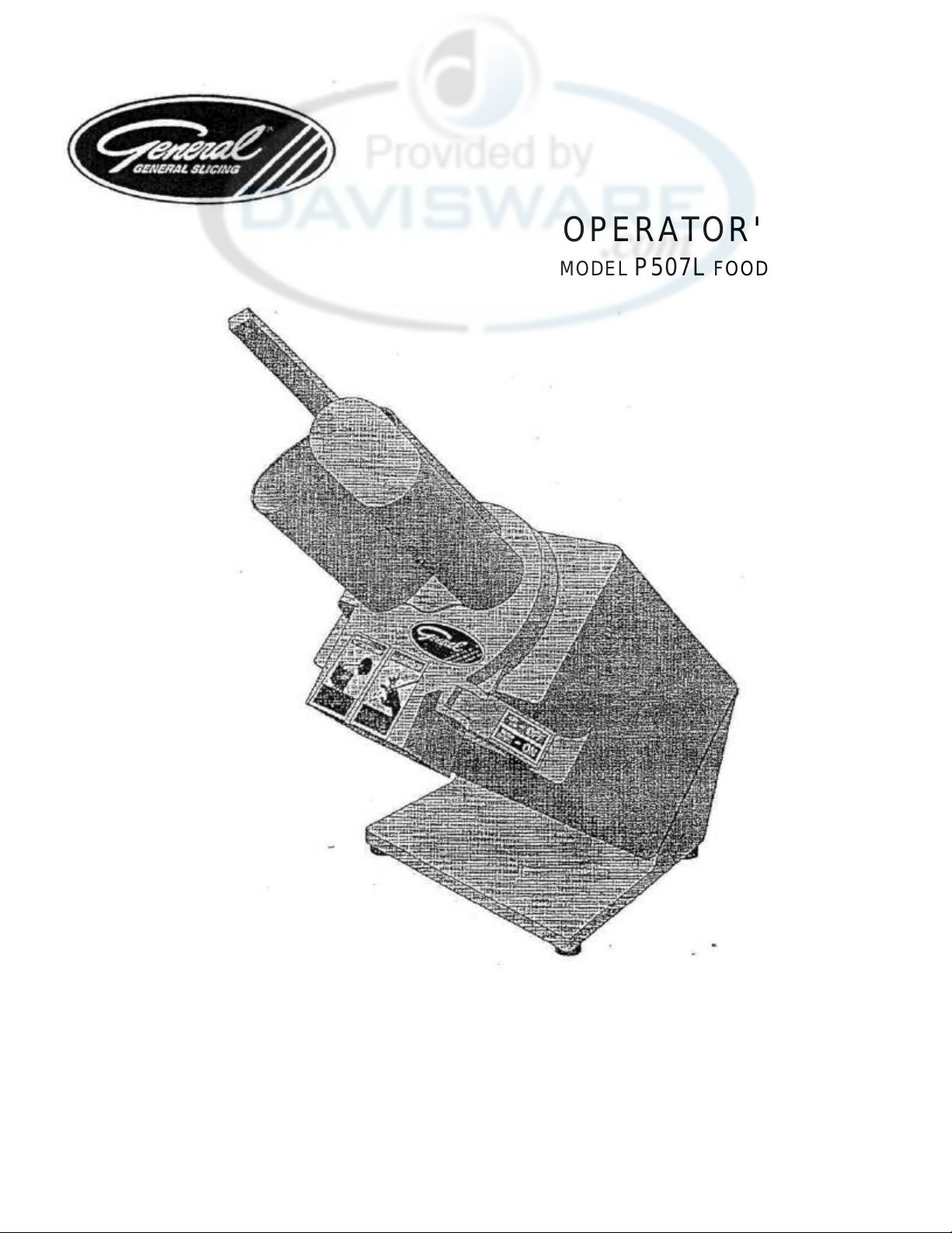
OPERATOR'S GUIDE
MODEL P507L FOOD PROCESSOR
Safety...............................................….............
General Description .........................…............
Unpacking and Handling .................….............
Cleaning ...........................................…............
Electrical Requirements...................….............
2
3
4
4
6
Disc Installation and Removal.…........................
Operation ...............................….........................
Lubrication .............................….........................
Parts Replacement and Service ........................
Replacement Parts...................….......................
6
8
9
9
9
Page 2
SAFETY
2
12.15.96
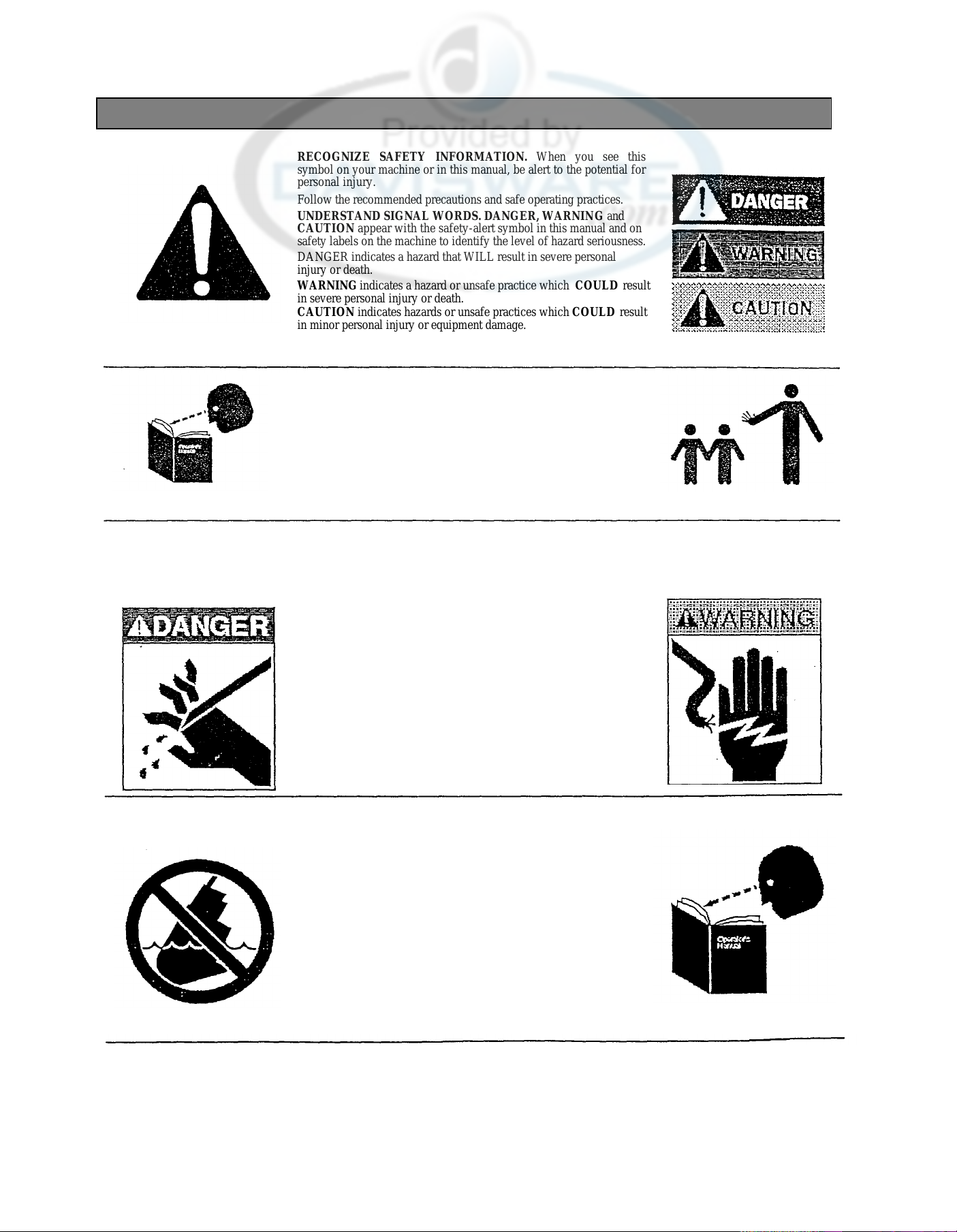
RECOGNIZE SAFETY INFORMATION. When you see this
symbol on your machine or in this manual, be alert to the potential for
personal injury.
Follow the recommended precautions and safe operating practices.
UNDERSTAND SIGNAL WORDS. DANGER, WARNING and
CAUTION appear with the safety-alert symbol in this manual and on
safety labels on the machine to identify the level of hazard seriousness.
DANGER indicates a hazard that WILL result in severe personal
injury or death.
WARNING indicates a hazard or unsafe practice which COULD result
in severe personal injury or death.
CAUTION indicates hazards or unsafe practices which COULD result
in minor personal injury or equipment damage.
READ ALL INSTRUCTIONS
Read this operator's manual before using the machine. Failure to follow the
instructions provided could result in personal injury or equipment damage.
KEEP OUT OF REACH OF CHILDREN
This processor is intended for commercial use only.
DO NOT FEED FOOD BY HAND.
Always use the foodpusher.
DO NOT OPERATE IF DAMAGED
Do not operate this processor with a damaged cord or plug, or if the
processor has been dropped or damaged in any manner. Contact the
nearest factory-authorized service center for examination, repair or
adjustment. (Refer to the service center list included in the Owner's
Information Packet.)
Do not allow the cord to touch hot surfaces.
Do not allow the cord to hang over the edge of a table or counter.
Do not allow the cord near cutting board.
DO NOT LEAVE PROCESSOR UNATTENDED.
UNPLUG PROCESSOR
Set the switch to OFF and unplug the processor from the
outlet when not in use and before cleaning or removing jams.
KEEP MACHINE AWAY FROM WATER
Do not let machine base stand in water.
Do not immerse the processor in water or any other liquid.
ATTACHMENTS
Do not use attachments not recommended by the
manufacturer.
Follow the manufacturer's instructions for use of
attachments.
SAVE THESE INSTRUCTIONS.
Keep this booklet in a convenient location for future
reference.
Page 3
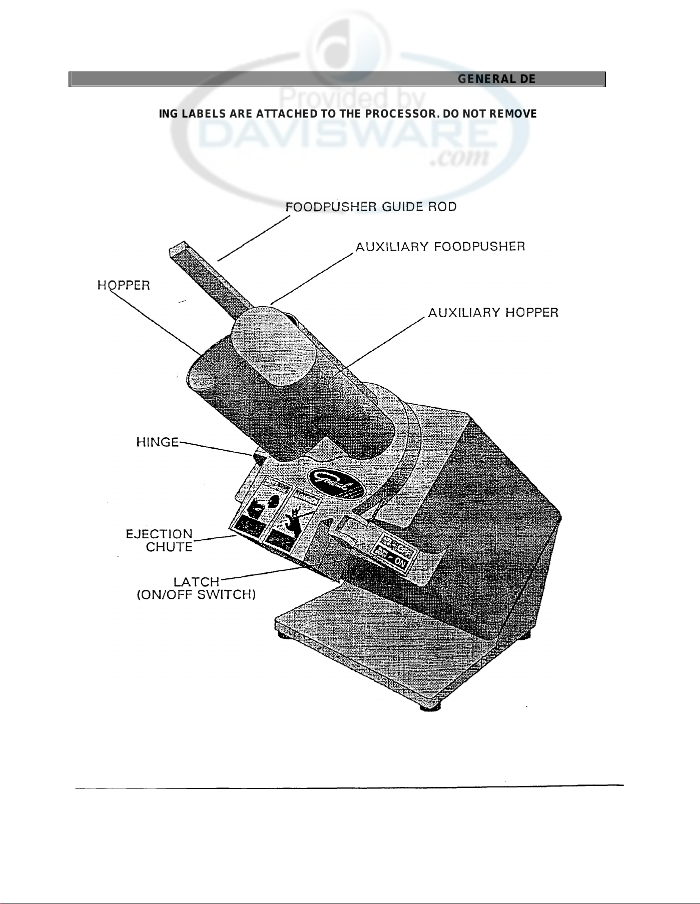
GENERAL DESCRIPTION
3
STD. EDITION 12.15.95
WARNING LABELS ARE ATTACHED TO THE PROCESSOR. DO NOT REMOVE THEM
Page 4
UNPACKING AND HANDLING
4
STD. EDITION
12.15.95
UNPACKING
The processor comes fully assembled and ready for use; however, inspect the
shipping carton and its contents for shipping damage. If you detect shipping
damage to any of the contents of the carton, notify your carrier.
If there are any parts missing, notify us immediately at 1-800-251-4232 or 615-
893-4820.
The processor should be thoroughly cleaned and sanitized before using to
ensure sanitary conditions. (See Cleaning Section.)
CAUTION: The processor should be installed on a level counter top
strong enough to safely support its weight.
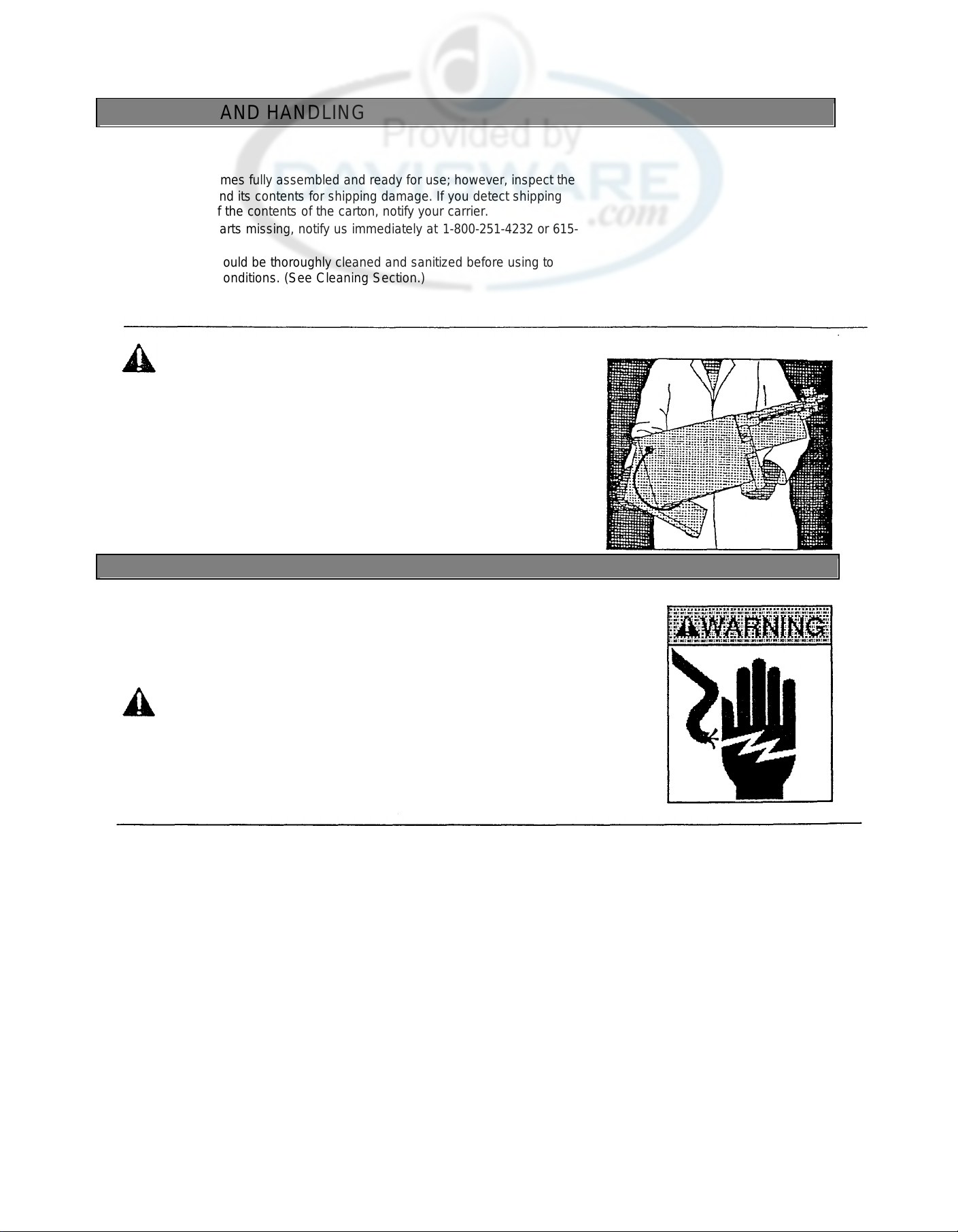
HANDLING AND MOVING
NOTE: Before moving, always unplug the machine, wind up the cord, and remove
cutting disc. Be sure that the latch is locked (in the ON position).
If possible, use a utility cart to transfer machine.
Carry the machine by grasping it with one hand under the ejection chute and one
hand under the housing.
CLEANING
DISASSEMBLY FOR CLEANING
Clean and sanitize the processor before using the first time, after each use, and before processing
different types of food products. Follow company, local, and state health/sanitation codes.
WARNING: Unplug the processor before cleaning or handling.
Do NOT use caustic or abrasive cleaners.
Do NOT wash the hopper head or discs in the dishwasher.
Hopper Head Assembly
1. Unplug the machine.
2. Unlock the hopper head latch by lifting it upward to OFF position and raise the
hopper head to full open position.
3. Pull out hinge pin.
4. Lift the head up and off machine.
5. Wash the hopper head in hot, soapy water. Remove all food particles and
juices from foodpusher guide rod. Apply a light coat of non-toxic mineral oil to
the foodpusher guide rod.
NOTE: Do not leave the hopper head soaking in water.
Page 5

STD. EDITION
12.15.95
5
Cutting Discs
WARNING: When handling discs, keep fingers and hands away
from the cutting edges.
NOTE: Always clean the cutting discs immediately after each use. (See the
Disc Installation and Removal Section for instructions on removing discs.)
NOTE: Before washing the cubing grid, remove the knife and cubing grid together,
then reinstall only the cubing grid. Press the cleaning brush into the grids to push
excess food into the hopper.
Use the brush supplied with the machine to wash cutting discs. Always brush
away from the cutting edges.
Wash the cutting discs and. cleaning brush in hot, soapy water.
CLEANING ... continued
Food Ejector and Housing
1. Grasp the food ejector by the hub and lift it off the disc drive shaft.
Wash the food ejector in hot, soapy water.
2. Wash the auxiliary foodpusher in hot, soapy water.
3. Clean all surfaces of the housing and cutting area with hot, soapy water and
a clean cloth.
REASSEMBLY
WARNING: Unplug the processor before handling.
1. Reinstall the hopper head by aligning the hinge with the
housing.
2. Replace the hinge pin.
3. Place the food ejector over the disc drive shaft and rotate it slightly back
and forth until the hub seats over the lower pin on the shaft.
4. Close the hopper head.
Page 6

ELECTRICAL REQUIREMENTS
6
STD. EDITION
12.15.95
Plug the processor into a properly grounded three-prong outlet. DO NOT use an
extension cord.
Use a 115 Volt, A.C., 60 Hz power source, as indicated on the Data Plate on the
back of the unit. To operate the unit on other volta ges, the processor must be
returned to the factory for modification.
All electrical connections must be made in compliance with all applicable local
electrical codes, as well as the latest edition of the National Electrical Code
(NFPA 70).
DISC INSTALLA TION AND REMOVAL
Tips for proper disc use:
• Keep the drive shaft and disc mounting hubs clean or the discs will not seat
correctly.
• Be sure the food ejector is seated correctly on the drive shaft before installing
cutting discs.
• Do not use force or tools to install and remove discs.
CAUTION: Keep fingers away from cutting edges of discs.
INSTALLING SINGLE DISCS
1. Open the latch and raise the hopper head to its full open position.
2. Place the disc, with hub down, on the drive shaft (on top of the food ejector), and
rotate it back and forth slightly until the upper drive pins engage in the slot on the
disc hub and the disc is fully seated.
NOTE: The ON switch will not engage if the disc is not installed correctly. If the ON
switch does not engage, reinstall the disc.
REMOVING SINGLE DISCS
1. Open the latch and raise the hopper head to its full open position.
2. Carefully place one hand (palm up) under disc and lift up at disc hub.
Page 7

DISC INSTALLATION AND REMOVAL... continued
INSTALLING DOUBLE DISCS
NOTE: The disc numbers are stamped on the under sides of the discs, except for the
cubing knife. The cubing knife number is stamped on top of the disc. Always use the
discs with corresponding numbers on the upper and lower discs; otherwise, the
processor will not function properly and may cause damage to the machine.
Installing Cubing Discs
1. Open the latch and raise the hopper head to its full open position.
2. Place the cubing grid (with the hub down) over the drive shaft. The disc will
rest on the circular shelf of the housing.
CAUTION: Keep fingers away from the cutting edge of the upper disc
(knife). Handle the knife by the thick side only.
3. Place the knife (with the hub down) on the drive shaft and rotate it slightly until
the pins engage in the hub and the knife is fully seated.
NOTE: The ON switch will not engage if the discs are not installed correctly. If the
ON switch does not engage, reinstall the cubing grid and knife.
Removing Cubing Discs
1. Open the latch and raise the hopper head to its full open position.
CAUTION: Keep fingers away from the cutting edge of the knife.
Handle the knife by the thick side only.
2. With right hand, turn the knife counter-clockwise so that the flat edge is
in the 3 o'clock position, as shown, and hold in that position.
3. Carefully place left hand (palm up) under cubing grid and lift up at disc
hub, removing cubing grid and knife at the same time.
7 STD. EDITION 12.15.95
Page 8

OPERATION
Clean and sanitize the processor before using the first time, after each use, and before
processing different types of food products. Follow company, local and state
health/sanitation codes. (See Cleaning Section.)
1. Install the cutting disc. (See Disc Installation and Removal Section.)
2. Place a container under the ejection chute.
3. Plug the power cord into a grounded three-prong outlet. (See Electrical
Requirements, Page 6.)
4. Trim the product to fit into the hopper. Food must not extend above top of hopper.
5. Slide the foodpusher up to its highest position and tilt it to the left.
NOTE: Feed carrots, cucumbers, and similar vegetables pointed end first. Feed
leafy foods such as lettuce, celery, and green onions leafy end first.
6. Place the product in the hopper (before engaging ON switch).
DO NOT FEED FOOD BY HAND.
Always use the foodpusher.
7. Slide the foodpusher up and to the right until the
foodpusher covers the hopper opening.
NOTE: Foodpusher must fully cover hopper
opening or processor will not start.
NOTE: The latch will not close and engage the ON switch if the disc is not
installed correctly. Do not use force. If the latch does not close, unplug
processor and reinstall the disc.
8. Engage the ON switch by closing the latch.
NOTE: Do not apply heavy pressure with the foodpusher while processing
or food will not maintain a uniform cut.
9. Press the foodpusher firmly to hold the product and keep it from rotating.
10. Repeat this procedure until all product is cut.
8 STD. EDTION 12.15.95
Page 9

LUBRICATION
…….1
…….1
LUBRICATION
The unit has permanently lubricated bearings. Do not add oil or grease.
Add a few drops of mineral oil to the foodpusher guide rod to keep it moving freely.
PARTS REPLACEMENT AND SERVICE
PARTS REPLACEMENT
Use the replacement parts list on Pages 9-11, and the parts distributors list included in
the Owner's Information Packet to order spare parts. Specify the model and serial
numbers, part number, and part name.
SERVICE
For repair consult the factory -authorized service centers list included in the Owner's
Information Packet for the closest service center.
REPLACEMENT PARTS
DISC AND ACCESSORY PARTS
QTY
KEY
NO. PART NO. NAME: DESCRIPTION MACH
1
SL1.5 SLICING DISC:1/16", 1.5MM ............... ....... 1
SL4.5 SLICING DISC:3/16", 4.5MM ........…... …… 1
2
12-GSM -631 BRUSH:DISC CLEANING ...........…..... …….1
3
SH4.5 SHREDDING DISC:3/16", 4.5MM........ ....... 1
4
JU2.0 JULIENNE DISC:5/64", 2.0MM ............ ....... 1
JU4.0 JULIENNE DISC:5/32", 4.0MM ...……. …….1
5
30-P -7200 CUTTERBEAM ASSY: JU2.0...............
30-P -7204 CUTTERBEAM ASSYJU4.0................ …….1
6
08-P -7203 SCREW, CUTTERBEAM:JU2.0, JU4.0
7
CU8.0 CUBING DISC:5/16", 8.0MM................ …….1
8
30-P -7208 CUBING KNIFE ASSY:CU8.0............... …….1
9
30-P -7207 CUBING GRID ASSY:CU8.0 …............ ....…1
STD. EDITION 12.15.95
9
PER
Page 10

REPLACEMENT PARTS
STD. EDITION 12.15.95
Page 11

REPLACEMENT PARTS PRICE LIST
5
30-P-7065 MAIN HOUSING ASSY........................
………………….…...1 786.00
NO. PART NO.
NAME: DESCRIPTION
EACH
1
**
2
631
**
3
**
4
**
**
5
6
7
8
9
MODEL: P507L
QTY. LIST
KEY
NO. PART NO. NAME: DESCRIPTION MACH. EACH
1 09-P-7037 EJECTOR PLATE……………………………………………...1 64.00
2 30-P-7024 DISC DRIVE SHAFT ASSY…………………………………..1 111.00
3 06-P-7C3a THRUST WASHER, UPPER ………………………………….1 11.00
4 09-P-7007 BEARING:DlSC DRIVE SHAFT……………………………...1 4.00
(INC:2-5,11-13 & 15-25)
6 05-P-7001 CORDSET ……………………………………………………...1 18.00
7 09-MM-2099 BUSHlNG:STRAlN RELIEF ……………………………….1 6.00
8 05-GSM-414 REED SWITCH ASSY:W/WlRE TERM…………………...2 25.00
9 30-P-7405 CONTACTOR ASSY:0.5HP/115V/1PH 1…………………….1 93.00
9A 05-P-7405 CONTACTOR, MINIIEC:9.6 AMP/AC3 ……………………...1 58.00
9B 05-P-7407 JUMPER ASSY:P507 CONTACTOR …………………………2 2.00
9C 05-P-7406 TERM BLOCK:2 POLE………………………………………..1 6.00
9D 04-P-7408 PLATE, MTG:CONTACTOR ASSY………………………….1 16.00
9E 08-6-250 SCREW:PHP HD.SLFTPG 8-32 X ½…………………………...2 1.00
9F 08-6-251 SCREW-.PHP HD.SLFTPG 8-32 X ¾….....………………..…...2 1.00
10 08-QSM-173 SCREW:ELEC. SUB. PLATE..............………………….….2 1.00
11 08-P-7066 KEY:DISC DRIVE SHAFT ..................…………………..…...1 1.00
12 08-P-7053 PIN:GEARBOX COVER ....................…………………..…….1 1.00
13 08-SM-1012 SCREW-.PN HD 4MA X 10 ..................……………………4 1.00
14 05-P-7003 TERMINAL, WIRE...............................…………………….…4 2.00
15 &8-P-7054 PIN:LATCH LOCK..............................………………….……1 4.00
16 07-P-7004 SEAL-12 X 22X7..................................………………………..1 7.00
17 06-P-7039 THRUST WASHER, LOWER ..............………………….……1 11.00
18 09-P-7040 GEAR. DRIVEN ...................................…………………...…..1 90.00
19 04-P-7041 SPACER:DISC DRIVE SHAFT, 3.9MM ………………...…. 1 6.00
04-P-7042 SPACER:DISC DR IVE SHAFT, 4.CMM …………………… 1 6.00
04-P-7043 SPACER:DISC DRIVE SHAFT, 4.1MM ………………….... 1 6.00
04-P-7C44 SPACER:DISC DRIVE SHAFT, 4.2MM .………………….. 1 6.00
04-P-7045 SPACER:DISC DRIVE SHAFT, 4.3MM ………………….... 1 6.00
04-P-7046 SPACER:DISC DRIVE SHAFT, 4.4MM ………………….... 1 6.00
04-P-7047 SPACER:DISC DRIVE SHAFT, 4.5MM ………………….... 1 6.00
20 07-P-7048 GASKET:GEARBOX COVER ..............……………………... 1 11.00
21 04-P-7050 GEARBOX COVER ...............................…………………….. 1 43.00
22 07-P-7049 SEAL-GEARBOX COVER ...................……………………... 1 9.00
23 09-P-7C08 BEARlNG:9X26X8. 2RS .....................…………………….... 1 7.00
PER PRICE
QTY. LIST
KEY
NO. PART NO. NAME: DESCRIPTION MACH. EACH
24 08-P-7067 NUT:HEX JAM M8 ..............................…………..... 2 2.00
25 06-P-7051 PLUG:GEARBOX COVER ..................…………..... 1 11.00
26 08-SM-1261 SCREW:CSK HD 8MA X 15 ................…………..... 4 2.00
27 04-P-7052 ADAPTOR PLATE:MOTOR................…………...... 1 35 .00
28 08-GSM-170 SCREW:SCKT HD 8MA X 20, BLK OX ………….. 4 2.00
29 30-P-7000 MOTOR ASSY:0.5HP, 115V/60HZ 1 429.00
(INC:29 & 29A)
29A 30-P-7055 PINION ASSY .....................................…………….... 1 70.00
30 30-P-7031 FOODPUSHER ASSY......................………………... 1 75.00
(INC:30&31)
31 06-P-7032 BUSHlNG:FOODPUSH ER ................…………….….1 4.00
32 30-P-7029 SHAFT:FOODPUSHER (GUIDE ROD)…………..…1 42.00
33 07-P-7005 SEAL-PLUNGER .................................………………1 4.00
34 30-P-7022 PLUNGER ASSY ..................................………………1 43.00
35 09-P-7006 BEARlNG:PLUNGER ..........................…………...….1 .00
36 08-P-7028 SPRING:PLUNGER...........................……………...…1 3 .00
37 08-P-7030 PIN, PIVOT-.FOODPUSHER SHAFT....………….…1
38 04-P-7026 HINGE PIN...........................................…………….…1 15.00
39 06-P-7036 BUSHING:HlNGE PIN ..........................………….….2 4.00
40 30-P-7023 FOODPUSHER:AUXILIARY...............…………...…1 37.00
41 30-P-7021 LATCH ASSY......................................…………….…1 90.00
(INC:41,43,44 & 53)
42 08-P-7027 PIN:LATCH PIVOT..............................………………1 13.00
43 08-P-7035 PIN:LATCH ROLLER..........................…………....…1 4.00
44 06-P-7034 ROLLER:LATCH ...................................………….….1 6.00
45 08-GSM-743 SCREW:PN HD M4 X 8 .......................…………...…4 1.00
46 04-P-7009 VENT PLATE .......................................…………...….1 26.00
47 08-P-7068 SCREW: RND HDM10X20...............……………...…4 2.00
48 07-P-7025 GASKET:SLANT BASE ........................…………..…1 11.00
49 50-P-7057 SLANT BASE .......................................…………….…1 179.00
50 06-P-7058 FOOT....................................................…………….…4 5.00
51 08-SM-1066 SCREW:CSK HD 5MA X 16 .............…………......…4 1.00
52 30-P-7020 HEAD ASSY. COMPLETE …………..........................1 536.00
(INC:30-37,39,41-44 & 53)
53 12-GSM-719 LABEL-SWITCH ON/OFF ........…………..................1 1.00
PER PRICE
7.00
DISC AND ACCESSORY PARTS
QTY. LIST
KEY
SL1.5 SLICING DISC:1/16-,1.5MM ................………………...1 **
SL4.5 SLICING DISC:3/16'. 4.5MM ..................…………….…1
12-GSM-
SH4.5 SHREDDING DISC:3/16", 4.5MM ...........………………1
JU2.0 JUUENNE DISC-.5/64', 2.CMM ...............………………1
JU4.0 JUUENNE DISC-.5/32', 4.0MM ...............……………….1
30-P-7200 CUTTERBEAM ASSY:JU2.0..................………………..1 28.00
30-P-7204 CUTTERBEAM ASSY-.JU4.0 ..................………………1 28.00
08-P-7203. SCREW, CUTTERBEAM:JU20, JU4.0 …………………1
CU8.0 CUBING DISC:5/16", 8.0MM...................…………….…1 9.00
30-P-72C8 CUBING KNIFE ASSY:CU8.0 ................………………..1 164.00
30-P-7207 CUBING GRID ASSY:CU8.0 ................………………...1 11 00
BRUSH:DISC CLEANING .....................………………..1
PER PRICE
** Refer to current equipment Price List for pricing of these items.
General Slicing/Red Goat Disposers • 1152 Park Ave • P.O. Box 428 • Murfreesboro, Tennessee 37133-0428 • (615) 893-4820
9.00
12.12.97
 Loading...