

Page 1
Ordering Instructions.......................................2
Safety..............................................................3
General Installation.........................................4
“H” Series Installation & Connection ...............5
“A” Series Installation & Connection...............6
“B” Series Installation & Connection...............7
“C” Series Installation & Connection ...............8
Typical Installation/Start-up & Run..................9
Operation/Troubleshooting............................10
Troubleshooting.............................................11
Maintenance .................................................12
Parts Replacement .......................................14
Motor Test Results........................................15
“H” Replacement Parts.................................16
“A” Replacement Parts .................................18
“B” Replacement Parts .................................20
“C” Replacement Parts.................................22
“RAC1” Replacement Parts..........................24
“RAC2” Replacement Parts..........................25
Warranty........................................................26
Red Goat Disposers
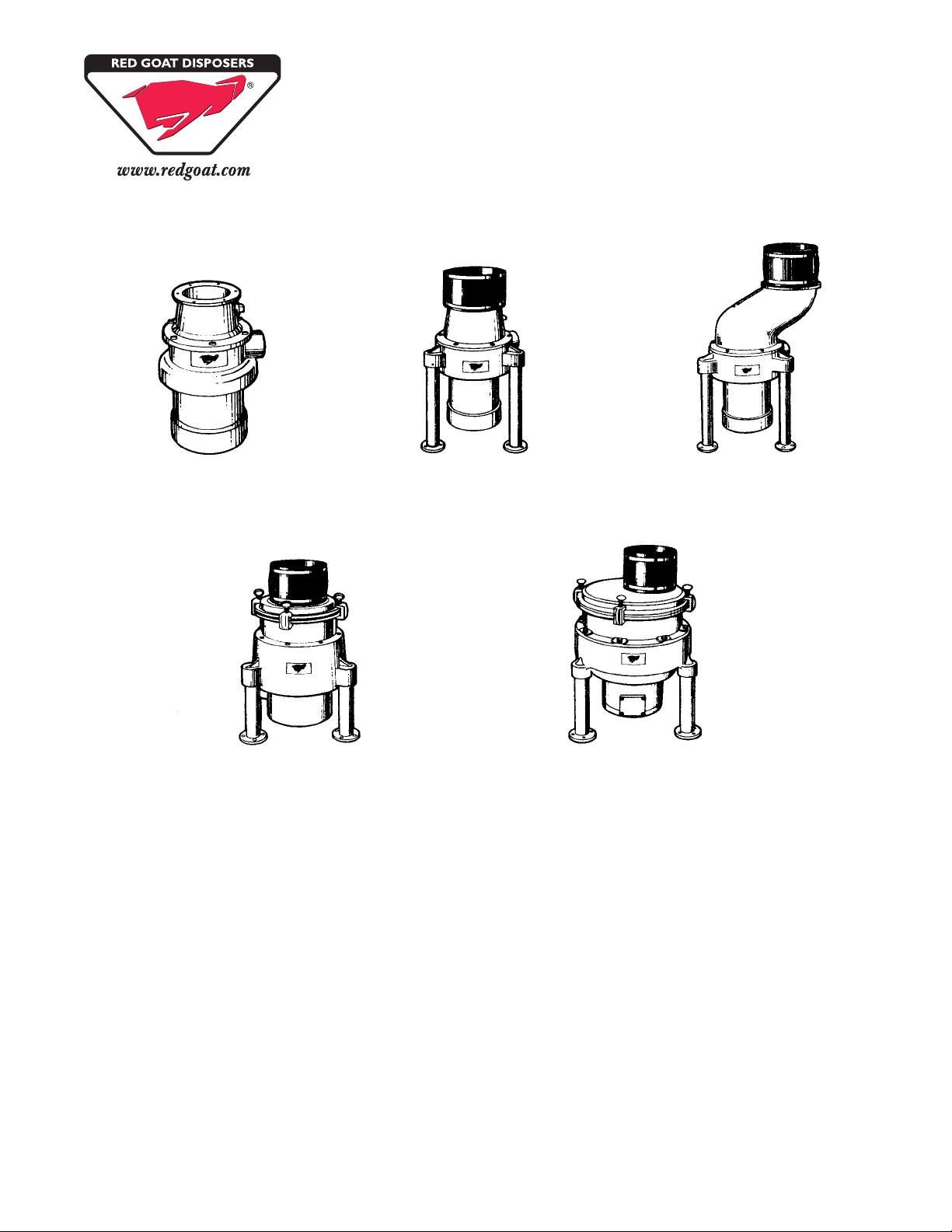
RED GOAT DISPOSERS
Installation • Operation • Maintenance
“H” Series “A” Series “A” Offset
“B” Series “C” Series
165 Independence Court • Lancaster, PA 17601
800.237.6628 • 717.397.5100 • FAX 717.397.1997
www.redgoat.com
Page 2

ORDERING INSTRUCTIONS
Contact the Factory-authorized Parts Distributor for all parts orders or contact us directly for the name and phone
number of the parts distributor nearest you:
Page 2
Call Toll Free: 800-237-6628
FAX: 717-397-1997
Red Goat Disposers 02/08
Page 3
Page 3
SAFETY
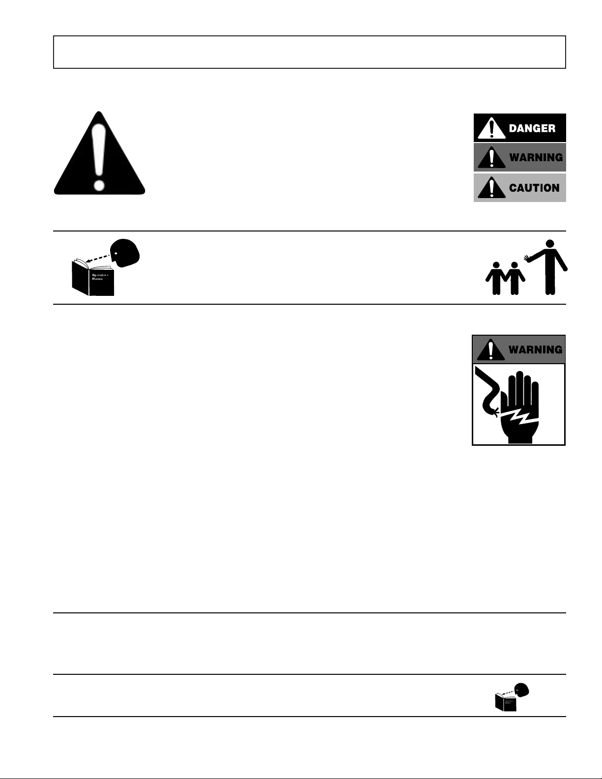
RECOGNIZE SAFETY INFORMATION. When you see this symbol on
your machine or in this manual, be alert to the potential for personal
injury.
UNDERSTAND SIGNAL WORDS. DANGER, WARNING and CAUTION
appear with the safety-alert symbol in this manual and on safety labels on
the machine to identify the level of hazard seriousness.
DANGER indicates a hazard that WILL result in severe personal injury or
death.
WARNING indicates a hazard or unsafe practice which COULD result in
severe personal injury or death.
CAUTION indicates a hazard or unsafe practice which COULD result in
minor personal injury or equipment damage.
READ ALL INSTRUCTIONS
Read this owner’s manual before using the machine. Failure to follow the
instructions provided could result in personal injury or equipment damage.
KEEP OUT OF REACH OF CHILDREN
This disposer is intended for commercial use only.
DO NOT PUT HANDS OR ANY IMPLEMENT IN THE DISPOSER
WHILE IN OPERATION.
NEVER FEED WASTE BY HAND PAST VINYL SILVER TRAP
SCRAPPING RING.
DO NOT OPERATE IF DAMAGED.
Do not install or operate this disposer if the disposer has been dropped
or damaged in any manner. Contact the nearest factory-authorized
service center for examination, repair or adjustment. (Refer to the service
center list included in the Owner’s Information Packet.)
DO NOT LEAVE DISPOSER UNATTENDED.
SET THE POWER SWITCH TO OFF BEFORE CLEARING JAMS OR
REMOVING OBJECTS FROM DISPOSER.
When the disposer is wired to a Manual Control or Model RAC1 Control
Center, SHUT OFF the branch circuit main switch or disconnect.
When disposer is wired to a RAC2 Control Panel, TURN OFF emergency
disconnect.
Use long-handled tongs or pliers to remove objects.
TO REDUCE THE RISK OF INJURY BY MATERIALS THAT MAY BE
EXPELLED BY DISPOSER, DO NOT PUT THE FOLLOWING INTO
DISPOSER: drain cleaner; glass, china or plastic; large, whole bones;
metal (bottle cas, tin cans, aluminum foil, etc.); whole cornhusks.
ALWAYS KEEP VINYL SILVER TRAP SCRAPPING RING OR SINK
STOPPER IN PLACE ON SERIES “H-RSA”, EVEN WHEN NOT IN USE.
This reduces the risk of objects falling into the disposer.
WHEN CLEANING KITCHEN AND DISPOSER AREA, ONLY DAMP
WIPE OUTSIDE OF DISPOSER AND CONTROLS. DO NOT AT ANY
TIME HOSE DOWN THE EXTERIOR SURFACES OF THE DISPOSER
AND CONTROLS.
SAVE THESE INSTRUCTIONS.
Keep this booklet in a convenient location for future reference.
Red Goat Disposers 02/08
Page 4

Page 4
GENERAL INSTALLATION
FABRICATING
1. Consult installation and connection data and installation diagrams on following pages for regular cone or regular
sink attachment dishtable cutout sizes.
2. For cone attachment, position cone so water swirl inlet fitting is nearest to operator.
3. Weld the total circumference of cone or sink attachment to prevent leakage.
4. Smooth grind and polish to match and blend weld seams.
NOTE: DO NOT PLACE CONTROL MOUNTING BRACKETS IN DIRECT WATER SPLASH AREAS.
PLUMBING
1. Consult installation and connection data and installation diagrams on following pages for mounting, hookups and
pipe sizes.
2. “H” Series is mounted by suspending from dishtable.
3. “A”, “B” and “C” Series use a floor leg support system with a neoprene connecting sleeve and two (2) stainless
steel clamps. Supplied sleeve (8” length) should be cut to required length for connection of disposer to dishtable.
4. Slide in, or position, disposer to connect to waste line, avoiding as many bends, elbows and tees as possible.
5. Flexible drain connection should be installed as follows:
A. Slip coupling over disposer outlet, then onto drain pipe.
B. Using a 5⁄16” nut driver, tighten to a torque of 60 in-lbs.
6. Perform power-rotor reaming of waste line whether connection is made to a new or old waste line. New lines
often contain foreign items left in the lines accidentally during construction.
7. Blow new water feed lines out before connections are made. Dirt, solder, or other foreign matter can lodge itself
in the flow controls, solenoid valve and vacuum breaker, causing malfunction.
8. Install solenoid valve. Check that inlet and outlet ports are in proper direction.
9. Check that disposer and dishtable opening are in line, level and true. This is visible when neoprene sleeve is
not kinked or partially collapsed. If level and in line adjustment is required, turn feet on bottom of legs.
10. Secure disposer to floor using the holes provided in the feet.
ELECTRICAL
NOTE: FOLLOW GUIDELINES SET FORTH BY NEC STANDARD AND LOCAL CODES.
1. Consult installation and connection data and diagrams on following pages for control placement and motor
wiring.
NOTE: DO NOT PLACE CONTROL IN DIRECT WATER SPLASH AREAS.
2. Follow supplied wiring schematics for all controls, solenoid valves and pre-wired custom control centers.
3. Size and fuse disposer branch circuit or use circuit breakers as required by motor nameplate rating.
4. Check that motor voltage wiring matches incoming voltage.
NOTE: ALL CONDUIT AND FITTINGS SHALL BE OF THE NEMA 4 WATERTIGHT TYPE.
5. All “H” and “A” disposers have thermal protection of the manual reset type, in motor. Check that reset button is
not jammed.
6. All “B” and “C” disposers must have thermal protection (heaters) in control. Check that heaters are sized properly
to prevent either motor burnout or nuisance tripping.
7. Check that all connections are tight, secure and well-grounded.
NOTE: Disposers are designed to operate in both a clockwise and counter-clockwise direction. Direction of rotation
does not have to be considered when wiring motor.
GROUNDING
Connect disposer to a grounded metal permanent wiring system or run a disposer grounding conductor with the circuit
conductors and connect it to the disposer grounding terminal or lead on the disposer.
Red Goat Disposers 02/08
Page 5

Page 5
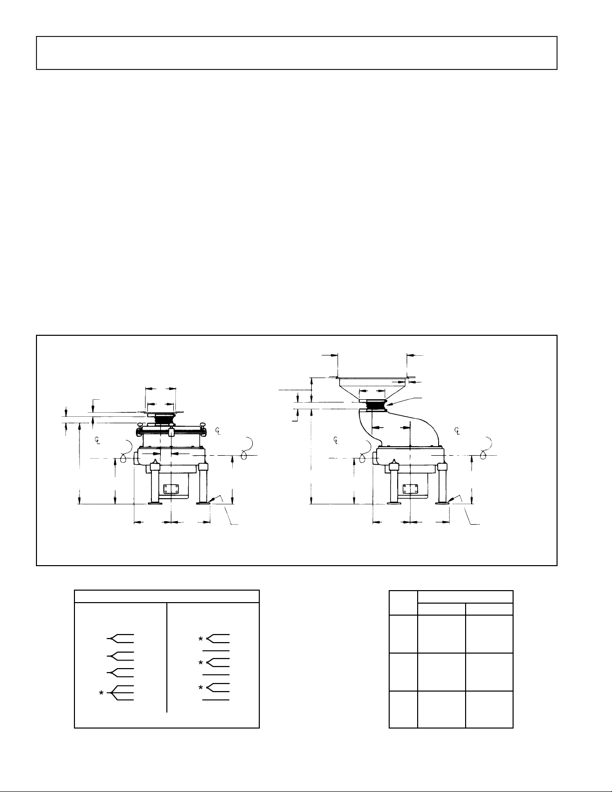
“H” SERIES - Installation and Connection
NOTE: PLUMBING AND ELECTRICAL CONNECTIONS SHALL BE MADE IN COMPLIANCE WITH APPLICABLE
LOCAL CONSTRUCTION CODES.
PLUMBING
Inlet: Cold water supply to disposer shall be 1⁄2" service line with a minimum of 20 lbs. flow pressure, piped as close to
disposer as possible. All disposer and control connections shall be 1⁄2" pipe size.
Sewer Outlet: 11⁄2" waste line should have trap with conveniently located clean out. Do not connect through a grease trap.
Avoid bends, elbows, tees, etc., to reduce the possibility of plumbing stoppage. Aglobe valve, used for metering flow, must
be installed between solenoid valve and cone or sink. Water swirl inlet valves should be located nearest operator.
See Typical Installation Diagram.
ELECTRICAL
Follow guidelines set forth by NEC standards. Disposer branch circuit shall be sized and fused (circuit breakers) as
required by motor. The disposer must be connected to a grounded, metal, permanent wiring system; or a disposergrounding conductor must be run with the circuit conductors and connected to the disposer-grounding terminal or lead
on disposer. All connections, junction boxes and conduits must be watertight (NEMA 4).
TESTING See Start-up and Run Section.
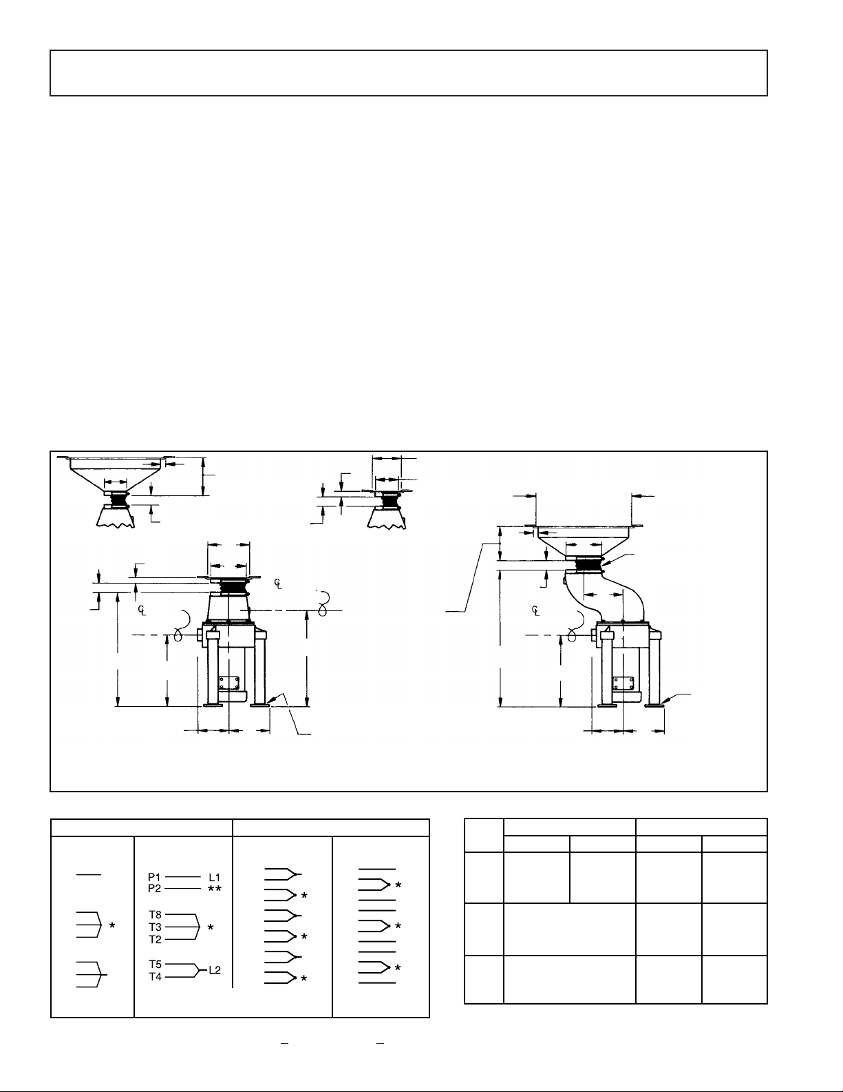
INSTALLATION DIAGRAM
MOTOR WIRING DIAGRAM VOLTAGE-AMPERAGE TABLE
31⁄4” INSIDE
DIAMETER
SINK MOUNTING ASSEMBLY
WILL FIT STANDARD 3
1
⁄2
”
TO 4” DIAMETER OPENING
TABLE CUTOUT
13” FOR 12” CONE
16” FOR 15” CONE
19” FOR 18” CONE
6” FOR 12” CONE
5” FOR 15” CONE
7” FOR 18” CONE
6
5
⁄8”
DRAIN
WATER INLET
3
1
⁄4”
9”
5
1
⁄2”
DRAIN
7
7
⁄8”
65⁄8
”
DISPOSER SHOWN WITH SINK MOUNTING ASSEMBLY DISPOSER SHOWN WITH CONE MOUNTING ASSEMBLY
SINGLE PHASE THREE PHASE
115 Volt, 60 Hz 230 Volts, 60 Hz 208/230 Volt, 60 Hz 460 Volt, 60 Hz
110 Volt, 50 Hz 220 Volts, 50 Hz 190-220 Volts, 50 Hz 380-440 Volts, 50 Hz
Tied Together and Insulated
Insulated
**
**
T1
T4
P4
T2
T8
T5
P5
T3
T9
T6
P6
T7
L1
L2
L3
L1
L2
L3
T1
T4
P4
T2
T8
T5
P5
T3
T9
T6
P6
T7
*
**
P1
T8
P2
T3
T5
T2
T4
L2
L1
SINGLE PHASE THREE PHASE
HP
Volts Amps* Volts Amps*
115 12.8 208 3.4
1 230 16.4 230 3.4
——460 1.7
*Ratings are for 60 Hz operation
193⁄8
” (WITH 3 PHASE MOTOR)
19
7
⁄8” (WITH 1 PHASE MOTOR)
18
1
⁄8” (WITH 3 PHASE MOTOR)
18
5
⁄8
” (WITH 1 PHASE MOTOR)
Red Goat Disposers 02/08
6 = Six 9 = Nine
Page 6
Page 6
“A” SERIES - Installation and Connection
NOTE: PLUMBING AND ELECTRICAL CONNECTIONS SHALL BE MADE IN COMPLIANCE WITH APPLICABLE
LOCAL CONSTRUCTION CODES.
PLUMBING
Inlet: Cold water supply to disposer shall be 1⁄2" service line with a minimum of 20 lbs. flow pressure, piped as close to
disposer as possible. All disposer and control connections shall be 1⁄2" pipe size.
Sewer Outlet: 2" waste line should have trap with conveniently located clean out. Do not connect through a grease trap.
Avoid bends, elbows, tees, etc., to reduce the possibility of plumbing stoppage. A globe valve, used for metering flow,
must be installed between solenoid valve and cone or sink. Water swirl inlet valves should be located nearest operator.
See Typical Installation Diagram.
ELECTRICAL
Follow guidelines set forth by NEC standards. Disposer branch circuit shall be sized and fused (circuit breakers) as
required by motor. The disposer must be connected to a grounded, metal, permanent wiring system; or a disposergrounding conductor must be run with the circuit conductors and connected to the disposer-grounding terminal or lead
on disposer. All connections, junction boxes and conduits must be watertight (NEMA 4).
TESTING See Start-up and Run Section.
INSTALLATION DIAGRAM
MOTOR WIRING DIAGRAM VOLTAGE-AMPERAGE TABLE
SINGLE PHASE THREE PHASE
HP
Volts Amps* Volts Amps*
115 17.2 208 5.1
1
1
⁄2 230 8.6 230 4.6
——460 2.3
208 6.9
2 N.A. 230 6.2
460 3.1
208 9.7
3 N.A. 230 8.8
460 4.4
*Ratings are for 60 Hz operation
41⁄2
” INSIDE
DIAMETER
TABLE CUTOUT
13” FOR 12” CONE
16” FOR 15” CONE
19” FOR 18” CONE
6” FOR 12” CONE
5” FOR 15” CONE
7” FOR 18” CONE
6
1
⁄4”
DRAIN
14
1
⁄2”
19”
27”
6
1
⁄4”
DRAIN
7”
141⁄2”
CUTOUT 5
1
⁄2”
6” FOR 12” CONE
5” FOR 15” CONE
7” FOR 18” CONE
ADJUSTABLE 0” TO 2”
23”
1” MIN.
6” MAX.
1” MIN.
6” MAX.
1” MIN.
6” MAX.
41⁄2” REGULAR DRUM WITH
CONE MOUNTING ASSEMBLY
41⁄2” REGULAR DRUM WITH
SINK MOUNTING ASSEMBLY
1”
1”
1”
8”
8”
8”
CUTOUT
WATER
INLET
4
1
⁄2”
1” MIN.
6” MAX.
1”
7”
8”
ADJUSTABLE
0” TO 2”
8” LENGTH OF NEOPRENE
CONNECTOR SLEEVE FURNISHED.
MAYBE CUT TO DESIRED LENGTH.
SINGLE PHASE THREE PHASE
115 Volt, 60 Hz 230 Volts, 60 Hz 208/230 Volt, 60 Hz 460 Volt, 60 Hz
110 Volt, 50 Hz 220 Volts, 50 Hz 190-220 Volts, 50 Hz 380-440 Volts, 50 Hz
Tied Together and Insulated
Insulated
**
**
T1
T4
P4
T2
T8
T5
P5
T3
T9
T6
P6
T7
L1
L2
L3
L1
L2
L3
T1
T4
P4
T2
T8
T5
P5
T3
T9
T6
P6
T7
*
**
P1
T8
P2
T3
T5
T2
T4
L2
L1
DISPOSER SHOWN WITH REGULAR 7” DRUM
AND SINK MOUNTING ASSEMBLY
DISPOSER SHOWN WITH OFFSET DRUM
AND CONE MOUNTING ASSEMBLY
NOTE: All dimensions shown at 0” foot height adjustment.
6 = Six 9 = Nine
Red Goat Disposers 02/08
Page 7
Page 7
“B” SERIES - Installation and Connection
NOTE: PLUMBING AND ELECTRICAL CONNECTIONS SHALL BE MADE IN COMPLIANCE WITH APPLICABLE
LOCAL CONSTRUCTION CODES.
PLUMBING
Inlet: Cold water supply to disposer shall be 1⁄2" service line with a minimum of 20 lbs. flow pressure, piped as close to
disposer as possible. All disposer and control connections shall be 1⁄2" pipe size.
Sewer Outlet: 2" waste line should have trap with conveniently located clean out. Do not connect through a grease trap.
Avoid bends, elbows, tees, etc., to reduce the possibility of plumbing stoppage. A globe valve, used for metering flow,
must be installed between solenoid valve and cone or sink. Water swirl inlet valves should be located nearest operator.
See Typical Installation Diagram.
ELECTRICAL
Follow guidelines set forth by NEC standards. Disposer branch circuit shall be sized and fused (circuit breakers) as
required by motor. The disposer must be connected to a grounded, metal, permanent wiring system; or a disposergrounding conductor must be run with the circuit conductors and connected to the disposer-grounding terminal or lead
on disposer. All connections, junction boxes and conduits must be watertight (NEMA 4).
TESTING See Start-up and Run Section.
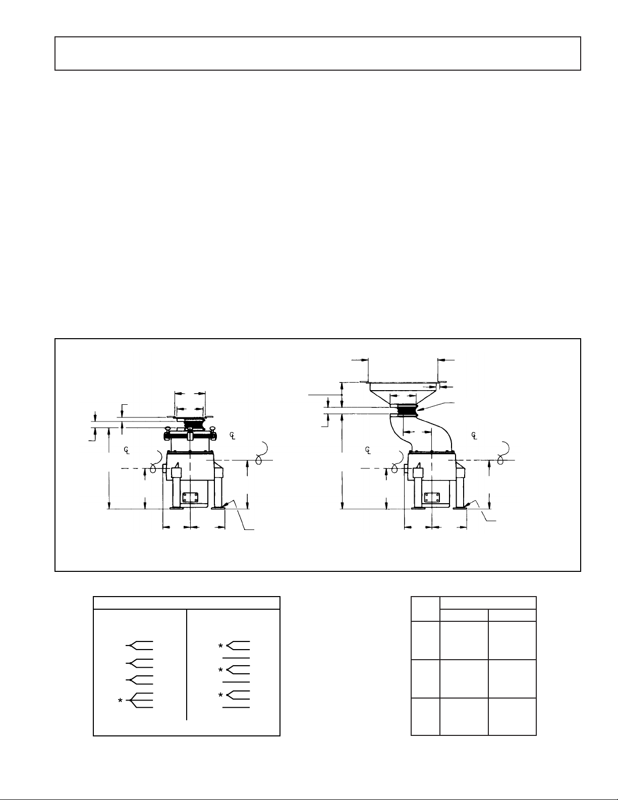
INSTALLATION DIAGRAM
MOTOR WIRING DIAGRAM VOLTAGE-AMPERAGE TABLE
THREE PHASE
HP
Volts Amps*
208 15.8
3 230 15.8
460 7.9
208 15.8
5 230 15.8
460 7.9
208 24.0
7
1
⁄2 230 23.0
460 12.0
TABLE CUTOUT
13” FOR 12” CONE
16” FOR 15” CONE
19” FOR 18” CONE
43⁄4” FOR 12” CONE
5
1
⁄2” FOR 15” CONE
6
1
⁄4” FOR 18” CONE
DRAIN
13
1
⁄2”
*
(141⁄2
”)
DRAIN
DISPOSER SHOWN WITH REGULAR DRUM
AND SINK MOUNTING ASSEMBLY
DISPOSER SHOWN WITH OFFSET DRUM
AND CONE MOUNTING ASSEMBLY
ADJUSTABLE 0” TO 2”
ADJUSTABLE 0” TO 2”
1” MIN.
6” MAX.
1” MIN.
6” MAX.
1” MIN.
6” MAX.
1”
7”
8”
8”
CUTOUT
WATER
INLET
7
3
⁄8”
1”
7”
8” LENGTH OF NEOPRENE
CONNECTOR SLEEVE FURNISHED.
MAYBE CUT TO DESIRED LENGTH.
NOTE: All dimensions shown at 0” foot height adjustment.
221⁄2”
(23
1
⁄2”)
*
111⁄2”
(12
1
⁄2”)
*
131⁄2”
(14
1
⁄2
”)
*
27”
(28)
*
111⁄2”
(12
1
⁄2”)
*
95⁄8”
7
3
⁄8”
9
5
⁄8”
WATER
INLET
THREE PHASE
208-230 Volts, 60 Hz 460 Volts, 60 Hz
190-220 Volts, 50 Hz 380 Volts, 50 Hz
Tied Together and Insulated
*
L1
L2
L3
1
7
2
8
3
9
4
5
6
4
7
1
5
8
2
6
9
3
L1
L2
L3
Red Goat Disposers 02/08
Page 8
Page 8
“C” SERIES - Installation and Connection
NOTE: PLUMBING AND ELECTRICAL CONNECTIONS SHALL BE MADE IN COMPLIANCE WITH APPLICABLE
LOCAL CONSTRUCTION CODES.
PLUMBING
Inlet: Cold water supply to disposer shall be 1⁄2" service line with a minimum of 20 lbs. flow pressure, piped as close to
disposer as possible. All disposer and control connections shall be 1⁄2" pipe size.
Sewer Outlet: 3" waste line should have trap with conveniently located clean out. Do not connect through a grease trap.
Avoid bends, elbows, tees, etc., to reduce the possibility of plumbing stoppage. A globe valve, used for metering flow,
must be installed between solenoid valve and cone or sink. Water swirl inlet valves should be located nearest operator.
See Typical Installation Diagram.
ELECTRICAL
Follow guidelines set forth by NEC standards. Disposer branch circuit shall be sized and fused (circuit breakers) as
required by motor. The disposer must be connected to a grounded, metal, permanent wiring system; or a disposergrounding conductor must be run with the circuit conductors and connected to the disposer-grounding terminal or lead
on disposer. All connections, junction boxes and conduits must be watertight (NEMA 4).
TESTING See Start-up and Run Section.
INSTALLATION DIAGRAM
MOTOR WIRING DIAGRAM VOLTAGE-AMPERAGE TABLE
TABLE CUTOUT
13” FOR 12” CONE
16” FOR 15” CONE
19” FOR 18” CONE
4
3
⁄4” FOR 12” CONE
5
1
⁄2” FOR 15” CONE
6
1
⁄4” FOR 18” CONE
DRAIN
13
1
⁄2”
DRAIN
DISPOSER SHOWN WITH REGULAR DRUM
AND SINK MOUNTING ASSEMBLY
DISPOSER SHOWN WITH OFFSET DRUM
AND CONE MOUNTING ASSEMBLY
ADJUSTABLE 0” TO 2”
ADJUSTABLE 0” TO 2”
1” MIN.
6” MAX.
1” MIN.
6” MAX.
1”
7”
10
1
⁄2”
8”
CUTOUT
WATER
INLET
10
1
⁄4”
1”
7”
8” LENGTH OF NEOPRENE
CONNECTOR SLEEVE FURNISHED.
MAYBE CUT TO DESIRED LENGTH.
NOTE: All dimensions shown at 0” foot height adjustment.
221⁄2”
(26
1
⁄2
”)
*
121⁄2”
13
1
⁄2”
27”
12
1
⁄2”
11”
10
1
⁄4”
11”
WATER
INLET
THREE PHASE
208-230 Volts, 60 Hz 460 Volts, 60 Hz
190 Volts, 50 Hz 380 Volts, 50 Hz
Tied Together and Insulated
*
L1
L2
L3
1
7
2
8
3
9
4
5
6
4
7
1
5
8
2
6
9
3
L1
L2
L3
THREE PHASE
HP
Volts Amps*
208 15.8
5 230 15.8
460 7.9
208 24.0
7
1
⁄2 230 23.0
460 12.0
208 29.2
10 230 28.6
460 14.3
Red Goat Disposers 02/08
Page 9
Page 9
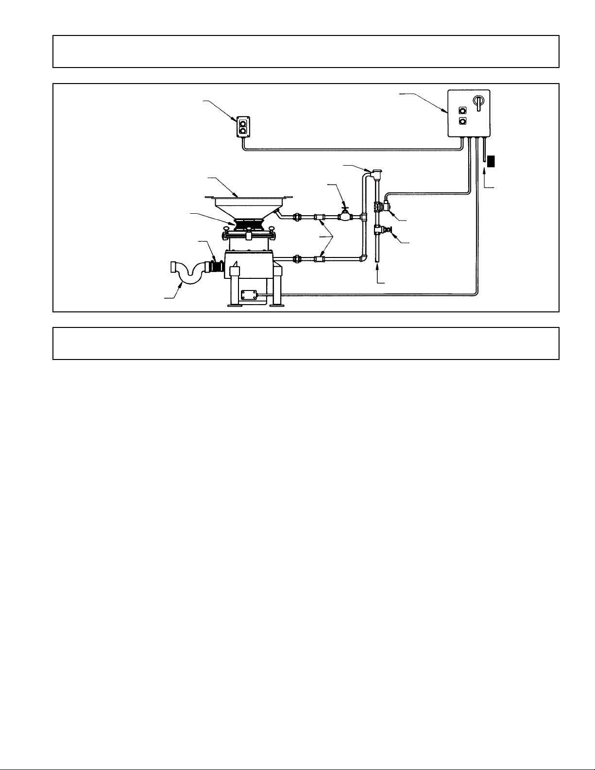
TYPICAL INSTALLATION
START-UP AND RUN CHECK
OPTIONAL REMOTE START/STOP SWITCH
POWER SUPPLY
SOLENOID VALVE
1
⁄2” COLD WATER
SUPPLY
FLOW
CONTROL
VALVE
3” FLEXIBLE DRAIN
CONNECTOR
VACUUM BREAKER
TYPICAL CONTROL PANELINSTALLATION:
AUTOMATIC REVERSING, NEMA 4X WITH
DISCONNECT SWITCH (MODEL RAC2)
CONE ASSEMBLYWITH WATER INLET VAL VE
CONNECTOR SLEEVE
TRAP
GLOBE VALVE
GATE VALVE
1. Check that vinyl silver trap scrapping ring is fully seated.
2. Check that all connections are secure.
3. Check that disposer is secured to floor.
4. Open terminal wiring box on motor; pull out and separate motor leads to permit ampere reading on each leg.
Leave all connections and insulation in place.
5. Clamp ammeter over input feed lead.
6. Turn on disposer.
7. Take ampere readings on each leg and verify against factory-checked motor test results (copy attached to
disposer and should be attached to Page 15 in this Owner’s Manual).
8. Check for leaks, water flow, excessive noise or vibration, and regulate water flow if required.
NOTE: Before checking rotation reversal, be sure disposer is empty. Wear safety glasses or goggles. BE SURE
POWER SWITCH IS OFF SHOULD ADJUSTMENTS ON DISPOSER BE NECESSARY. NEVER REACH INTO
DISPOSER WHEN DISPOSER IS RUNNING.
9. If disposer is connected to a reversing control, whether automatic or manual, check reversing.
10. If disposer is connected to a manual reversing drum switch or contactor, START motor in forward position and
note rotation through top opening as motor coasts to a stop. RESTART motor in reverse position. Verify that
disposer restarted in opposite direction.
11. If disposer is connected to a control center with automatic reversing (Model RAC1), verify if disposer reverses.
NOTE: Motor must be stopped or 30 seconds must have elapsed before pushing START; otherwise, motor will
not reverse. This is a safety cycle feature. Should START button be pressed earlier, motor will just run in same
direction. Push START. When disposer runs, press STOP and note coast down direction. When motor has
stopped, push START and note reversing of rotation.
12. If disposer is wired with a RAC2, rotation reversing is done the same as #1 1 above, except that the control panel
will first switch over to a 2-minute clean-out cycle, as shown by the green light. Verify this time, keeping the
solenoid valve open and motor running. When the 2 minutes have elapsed and motor has stopped, turn ON
disposer and note rotation.
13. In all shutdown phases, be sure water is being shut off by the closing of the solenoid valve.
14. Reinsert all wiring, close all covers and shut all doors that were open during run check.
Red Goat Disposers 02/08
Page 10

Page 10
OPERATION
1. Check that disposer is empty and clean from previous use.
2. Check that vinyl silver trap scrapping ring is in place and properly seated over throat opening in cone or sink.
3. Turn disposer ON. Note that water is flowing into top cone or into sink via the water swirl fitting.
WARNING: Never feed waste by hand past vinyl silver trap ring or reach inside running disposer.
NOTE: Do not feed metal, wood, cloth, rubber, corn husks, plastics, plastic sheets of bags, styrofoam, or other foreign
matter. A periodic clean out of such material from the disposer is advisable.
4. Proceed with dish cleanup, feeding waste gradually. DO NOT pack waste into disposer waste chamber.
5. After each use, if disposer is wired with manual controls, allow disposer to run (motor and water) for at least 2
minutes. This clean-out cycle will empty the disposer and flush the waste line, preventing potential drain
stoppage.
6. Should motor stop during use cycle, SHUT OFF POWER IMMEDIATELY, via ON-OFF switch. If disposer is
connected to Model RAC2 Control Center, shut OFF power at black emergency disconnect handle; on manual
switches, turn branch circuit disconnect to OFF.
A. Remove vinyl silver saver scrapping ring and check waste chamber through top opening and remove foreign
objects that may have caused stoppage.
B. Check to see if rotor turns freely.
C. If rotor turns freely, replace vinyl silver saver scrapping ring and turn disposer ON.
If disposer fails to start and run, an obstruction may still be binding the rotor.
A. Turn disposer OFF. Using a wooden bar or wooden handle, pry and push against the impact bars on the
rotor to break it free; then remove object.
B. Turn disposer ON and if motor fails to start, the thermal protector, either in the motor (“H” and “A” Series) or
in the controls, may have tripped.
C. Push reset button on thermal protector.
If disposer still fails to start, check for blown fuses or tripped circuit breakers in the branch circuit (especially on
three-phase installations) to be sure that all power legs are feeding motor.
TROUBLESHOOTING
DISPOSER DOES NOT START WHEN NEW
Manual reset button of thermal protector is tripped. On “H” and “A” Series, reset button is on motor; on “B” and “C”
Series, reset button is in control box.
Fuses or circuit breaker on branch circuit feed line have tripped.
Electrical connectionf on motor, in panel or feed lines not tight.
Headers have not been installed in starter, if starter is used in circuit.
DISPOSER DOES NOT START AFTER STANDING UNUSED FOR A PERIOD OF TIME
Clean out cycle too short. When disposer is stopped too early, the remaining water slowly drains out carrying the
shattered waste particles into the very close clearance opening between sizing ring and rotor, where it hardens and
solidifies, acting as a binding agent between the two parts. The motor at start-up is unable to overcome the dried
blockage (usually on low horsepower disposers).
DISPOSER STALLS WHEN IN OPERATION
Large quantities of foreign material (rags, wood pieces, rubber bands, strings, pieces from floor mops, cellophane
and polyethylene) which will not disintegrate, cause the motor to overheat and the thermal protector to trip.
Not enough water volume flow (GPM) causing thermal protector to trip.
Thermal protectors (heaters) sized too small, causing nuisance tripping.
Red Goat Disposers 02/08
Page 11

Page 11
TROUBLESHOOTING
(continued)
DISPOSER OPERATES BUT DISINTEGRATION AND DISCHARGE IS SLOW
Not enough water volume flow (GPM).
Worn shattering mechanism (impact bars, sizing ring, rotor).
Large amounts of foreign material in waste chamber.
DISPOSER MOVES WHEN STARTED
Large amounts of unshattered waste in chamber.
Rotor unbalanced due to loose impact bar.
Disposer not anchored to floor.
DRAIN LINE CLOGS
Worn shattering mechanism (impact bars, sizing ring, rotor) permitting large waste particles to flow through.
Large amount of paper and non-food particles being fed into disposer.
Not enough water volume flow (GPM).
DISPOSER DOES NOT TURN OFF (AFTER CLEAN OUT CYCLE, IF WIRED WITH RAC2)
Stop button in switch or control defective.
Timer in Model RAC2 control center defective.
DISPOSER DOES NOT REVERSE
Contacts in manual reversing switch burned.
Contactor in auto reversing control center defective.
Reversing circuit in auto reversing control center defective.
Time lapse safety circuit in auto reversing control center defective.
Motor not wired as indicated in wiring diagram.
SEVERE VIBRATION DURING OPERATION
Loose or broken impact bars.
Unshattered waste lodged in rotor.
Severe rotor damage from metal objects being fed into disposer.
MOTOR RUNS BUT NO WATER FLOW
Solenoid valve improperly wired.
Defective solenoid valve coil.
No water flow in main feed line.
MOTOR NUT TURNING AT PROPER RPM
Low voltage on incoming feed line.
On three-phase hookups, no voltage on one feeder line (leg).
Motor not wired as indicated in wiring diagram (low to high, high to low voltsO.
LOUD NOISE FROM MOTOR AREA
Upper or lower or both bearings worn.
Leakage of disposer seals.
SMOKE OR BURNING ODOR FROM MOTOR
Incoming voltage not correct.
On three-phase hookups, no voltage on one feeder line (leg).
Water leaking into motor through faulty seals.
Disposer being overloaded, especially with foreign material.
Improper motor connections.
Red Goat Disposers 02/08
Page 12

Page 12
TROUBLESHOOTING
MOTOR BURNS OUT
Internal winding short.
Water leaking into motor through faulty seals.
Disposer being overloaded.
Incoming voltage not correct.
Thermal protectors (heaters) not tripping, sized too large.
WATER LEAKING FROM BASE OR DISPOSER
Defective seals.
Hole worn in base.
Motor mounting screws not sealed on “H” and “A” Series units.
Leaking plumbing connections or leaking sink mounts.
WATER SPLASHING UP FROM DISPOSER
Building water pressure too high.
Globe valve not installed or needs adjustment.
WATER FLOWS BUT MOTOR DOES NOT RUN
Thermal protectors (heaters) not installed in starter.
Motor not wired as indicated on wiring diagram.
Control not wired correctly.
MAINTENANCE
Waste disposer troubles usually involve plumbing. Apreventative maintenance program is advisable to keep waste line
stoppage and disposer repair at a mininum. Any sewer problem occurring shortly after your disposer has begun
operation cannot be caused by the new machine. It will be the result of connecting to either an inadequate waste line,
or to one that has not been properly cleared before use. On the other hand, if waste line clogging occurs after the
disposer has been running trouble-free for a year or more, this indicates probable need for servicing.
The slurry leaving a new disposer contains no discernible solids, so there is nothing to clog the waste line. In regular
use, however, wearing of the working parts is to be expected. As the gradual wear occurs, the solid particles passing
through the wider gaps in the shatter mechanism will grow increasingly larger, until waste line stoppage may result.
See Figures.
MONTHLY WEAR CHECK
NOTE: The following should be performed every two weeks if waste is of a highly abrasive consistency.
1. Shut OFF branch circuit power, or emergency disconnect on control panel when disposer has completed its
clean out cycle.
2. Loosen stainless steel clamps on neoprene connector sleeve.
3. Twist neoprene sleeve loose and remove.
4. On “B” and “C” Series, loosen Quick-Release body clamps and lift off aluminum lid.
5. Remove any foreign objects (rubber bands, metal, wood, plastics, etc.) from waste chamber.
6. Check free movement of rotor.
7. The two points of probable wear are the leading edges of the impact bars and the spacing between the outer
edges of the rotor and the inner diameter of the sizing ring teeth (Figure 1, Page 13). When one end of each
impact bar is worn rounded, as shown in Figure 2, Page 13, they need to be reversed (if disposer is wired to an
automatic reversing control).
A. Loosen four hex socket head cap Allen screws to release the bars. Should it be necessary, use liquid wrench
or a mixture of oil and kerosene to help loosen the screws.
(continued)
Red Goat Disposers 02/08
Page 13

Page 13
MAINTENANCE
B. Reverse bars and reinstall Allen screws.
C.
8. The second point of wear is the clearance between the outer edge of the rotor and the inner diameter of the
sizing ring teeth (Figure 3).
If the space between the rotor and sizing ring has grown to 3⁄32”, (.094) and the impact bars are worn (rounded)
as shown in Figure 3, replacement of total rotor and sizing ring is advisable. See below and Page 14.
NOTE: If 3⁄32” space between rotor sna sizing ring is left to continue to increase, waste line stoppage may result as
increasingly large whole sections of waste will pass through sizing ring without breaking up.
When the rotor and sizing ring are new,
this spacing is 0.12” (less then 1⁄64”).
POINTS OF WEAR
FIG. 1
When these impact bars are reversed,
presenting new working sides, this
disposer will function well even though
this space may have grown to 3⁄32”.
At this stage of wear, no new parts
are needed.
With uniform wear on the rotor and the
teeth, spacing between has increased,
but the new faces of the reversed bars
restore efficiency.
These bars are badly worn and need reversing. FIG. 2
Remove Allen screws and reverse bars.
At this stage of double wear on bars,
this space may be 3⁄32” (.094). Check
with feeler gauge or U.S. Std. #13 gauge
wire.
At this stage, bars only may be
renewed–provided spacing between
rotor and teeth has not grown to 3⁄32”
and if waste line appears capable of
handling the slurry output.
These bars have had their double life. FIG. 3
With both sides well worn, it is evident that this disposer was
properly cared for, getting maximum length of service from all parts.
When the edges of the reversed impact bars become rounded (Figure 3), the bars must be replaced.
See below and Page 14.
(continued)
Red Goat Disposers 02/08
Page 14

Page 14
PARTS REPLACEMENT
WARNING: ALWAYS SHUT OFF MAIN POWER DISCONNECT BEFORE PERFORMING
MAINTENANCE OR PARTS REPLACEMENT.
IMPACT BARS (Series A, B and C)
1. Shut off main power disconnect.
2. Disconnect water line feeding into waste chamber, if applicable.
3. Loosen stainless steel clamps and remove neoprene sleeve.
4. On Series “A” disposers, remove 41⁄2” or 7” waste chamber by loosening and removing the six hex head bolts
holding chamber to base.
On Series “B” and “C” disposers, remove aluminum lid by loosening quick-release head clamps.
5. Insert wedge at impact bar between rotor and sizing ring to prevent rotor rotation.
6. Loosen hex socket head cap Allen screws and remove impact bars. Use liquid wrench or a solution of oil and
kerosene if necessary.
7. Install new impact bars in milled slots, after cleaning slots of foreign materials. Be sure new bars fit tightly into
slots and sit flatly, making metal to metal contact.
8. Remove anti-rotation wedge.
9. Replace removed components and reconnect disposer to sink or dishtable.
ROTOR AND/OR SIZING RING
1. Shut off main power disconnect.
2. Disconnect water line feeding into waste chamber, if applicable.
3. Loosen and disconnect disposer from sink or dishtable.
4. Remove waste chamber by loosening and removing the hex head bolts holding chamber to base.
5. Remove center cover bolt and plate.
6. Remove the two centering hold down studs from sizing ring and lift off sizing ring.
7. Remove old gaskets from base sizing ring or waste chamber.
8. Lift off rotor. On “B” and “C” Series, provisions for use of a wheel puller are cast into rotor. When using wheel
puller, thead back cover bolt onto motor shaft 1⁄2”. This will protect the threaded motor shaft.
9. Remove key from shaft.
10. Clean and inspect keyway.
11. Inspect motor seal system. If replacement is necessary, do so now. See Instructions on Page 13.
12. Oil motor shaft and slide on new rotor. Be sure rotor has seated fully on motor shaft shoulder and that shaft is
below machined surface on rotor.
13. Reinsert key. Series “B” and “C” use two keys. BE SURE the keys make metal to metal contact on all surfaces
in the rotor and motor shaft keyways and that the key is the full length of the keyway. Short keys will shear at
peak loads. Rotate rotor slightly to be sure there is no radial play between the rotor and motor shaft.
14. Insert cover gasket, plate and bolt to lock down rotor.
15. Torque cover bolt to 34 ft-lbs.
16. Install one new gasket on base.
17. Place sizing ring over gasket on base and thread in new centering studs.
18. Center sizing ring on rotor, turning rotor several complete turns. There should now be approximately 1⁄64” running
clearance between rotor and sizing ring.
19. Lock sizing ring into place with the centering studs. BE SURE sizing ring did not move and that running
clearance has been maintained.
20. Place the second gasket over centering studs and install waste chamber.
21. Lock waste chamber into place and reconnect parts removed earlier.
Red Goat Disposers 02/08
Page 15

Page 15
PARTS REPLACEMENT
MOTOR SEALS AND/OR MOTOR
1. Shut off main power disconnect.
2. Disconnect disposer from dishtable and waste line; remove floor mount and disconnect electric line feeding
motor.
3. Slide out disposer.
4. Remove rotor and sizing ring, as described on Page 14.
5. Series “H” and “A”: Remove four (4) motor bolts.
Series “H” and “A”: Turn disposer over resting base, especially sizing ring clamping surface, on wooden blocks.
6. Series “B” and “C”: Remove four (4) motor bolts and lift off motor.
Series “B” and “C”: Drive out the lip seal and cartridge seal; clean seal seating area.
Series “B” and “C”: Turn base over and set in the new lip seal (open side of seal facing up) and oil with SAE 30
oil.
7. Install cartridge seal.
A. Place light application of Permatex adhesive gasket sealant or equivalent in seal bore in base.
B. Fully immerse new cartridge seal in SAE 30 oil.
C Install new cartridge seal (rubber seal ring up), using installation tool (available separately) making sure seal
is fully seated in bore.
8. Turn base back onto the wooden blocks.
9. Clean motor shaft and oil shaft well with SEA 30 oil.
10. Slide motor back over seals and fasten motor. BE SURE motor is in same position as before for electrical
connections.
11. Turn base with motor back over and make sure rubber seal ring on cartridge seal is in place.
12. Re-install components, as listed on Page 14 and reconnect disposer.
TEST RESULTS
ATTACH FACTORY CHECKED MOTOR TEST RESULTS HERE
(continued)
Red Goat Disposers 02/08
Page 16

“H” SERIES REPLACEMENT PARTS LIST
Page 16
QTY.
KEY PER
NO. PART NO. NAME: DESCRITION MACH.
1 30-H-RSA RSA Head Assy ...................................1
(includes 2-9)
2 06-H-8 Sink Stopper: “H” Series RSA.............1
3 27-H-15 Sink Mount: Threaded.........................1
4 07-H-19 Gasket: RSA Rubber...........................1
5 07-H-20 Gasket: RSA Fiber...............................1
6 08-H-21 Screw, Hxhd 5/16-18 x 3/4..................6
7 08-HA-311 Washer: Lock Split 5/16.....................13
8 51-H-17 RSA Head............................................1
9 07-H-18 Gasket: Splash Guard.........................1
10 06-HA-ST4 Silver Saver: 4
1
⁄2”.................................1
11 07-H-34 Gasket: “H” Series Cone.....................1
12 08-HA-22 Screw: Hxhd 5/16-18 x 1, SS..............4
13 51-H-12LD Drum....................................................1
14 08-HA-17 Nut: Hex 6116-18.................................2
15 10-5-27 Pipe Plug:
1
⁄2”.......................................1
16 Gasket: Sizing Ring.............................2
17 08-HA-16 Centering Stud.....................................2
18 Sizing Ring ..........................................1
19 08-6-276 Nut: Hex Jam Nyloc, 5/8 x 18, SS.......1
20 08-6-277 Washer: Flat, H D.5/8 x .134 thick ......1
21 07-6-98 Gasket: Turntable Mounting ................1
22 Rotor: With Cast-On Impact Bars........1
23 07-HA-83 Cartridge Seal......................................1
04-HA-263 Install. Tool: HA Cartridge Seal............1
24 08-5-24 Screw: Skhd 3/8-16 x 3/4 Nyloc SS....4
25 30-H-1140 Base Assy: Includes Seals Installed....1
26 06-5-849 Drain Coupling: “H” Series ..................1
27 07-HA-5 Gasket: Motor/Base.............................1
28 30-H-431 Motor: 3/4 HP, 1PH..............................1
(includes 19-21 & 28)
29 02-H-479 Thermal Protector ................................1
30 02-MC-7500 Capacitor: 540-648MF, 120V...............1
28 30-H-432
(includes 19-21 & 28)
29 02-H-326 Thermal Protector: #MWJ69KB...........1
28 30-H-523 Motor: 1 HP, 1PH.................................1
29 02-MC-6068 Thermal Protector: #CEJ53CB............1
30 02-MC-7500 Capacitor: 540-648MF, 120V...............1
28 30-H-524 Motor: 1 HP, 3PH.................................1
(includes 19-21 & 28)
29 02-H-303 Thermal Protector: #MWJ66KB...........1
28 30-H-433 Motor: 1.25 HP, 1PH............................1
(includes 19-21 & 28)
29 Thermal Protector: #CEJ50CA............1
30 02-MC-7500 Capacitor: 540-648MF, 120V...............1
28 30-H-434 Motor: 1.25 HP, 3PH............................1
(includes 19-21 & 28)
29 Thermal Protector: #MWJ64KB...........1
28 30-H-435 Motor: 1.5 HP, 1PH..............................1
(includes 19-21 & 28)
29 02-MC-6070 Thermal Protector: #CEJ38CA............1
30 02-A-477 Capacitor: 460-552MF, 120V...............1
02-A-476 Capacitor: 17.5MF, 240V.....................1
QTY.
KEY PER
NO. PART NO. NAME: DESCRITION MACH.
28 30-A-436-524 Motor: 1.5 HP, 3PH..............................1
(includes 19-21 & 28)
29 02-H-462 Thermal Protector: #MWJ57KB...........1
28 30-A-480 Motor: 2 HP, 1PH.................................1
(includes 19-21 & 28)
29 02-H-463 Thermal Protector: #CWJ54KF ...........1
30 02-A-332 Capacitor: 590-708MF, 120V...............1
02-5-487 Capacitor: 50MF, 240V ........................1
28 30-A-437 Motor: 2 HP, 3PH.................................1
(includes 19-21 & 28)
29 02-5-486 Thermal Protector: #BEJ44DB............1
31 06-5-505 Rubber Boot: Thermal Protector .........1
32 30-HA-506 Conduit Box Assy................................1
33 08-HA-282 Key: Woodruff 1606 .............................1
34 02-HA-521 V-Ring Seal..........................................1
35 02-HA-522 Seal: Motor Shaft, “H” & “A” Series.....1
36 02-5-400 Bearing: #205......................................1
37 02-HA-508 Capacitor Housing...............................1
38 02-HA-520 Clamp: Fan..........................................1
39 02-H-466 Fan, Ext: Leeson 145 Frame...............1
40 02-H-467 Fan Guard: Leeson 145 Frame...........1
41 08-SN-1219 Bearing: #203......................................1
42 02-H-016 Cast Endshield “H” Leg Kit..................1
43 Nut: Hex
1
⁄2” - 13..................................1
44 08-C-1095 Washer: Lock Split
1
⁄2” .........................1
45 04-H-287 Mounting Plate “H” Leg Kit..................1
46 09-A-931 Leg Assembly “H” Series.....................1
47
48 08-BC-312 Washer, Lock Split
3
⁄8”..........................1
40-H-504 A-Complete Renewal Kit .....................1
(S/N 060185H01 forward)
40-H-500 H-Complete Renewal Kit.....................1
(Thru S/N 060185h29)
40-H-1DA H-Rotor Kit (includes 19-22) ................1
40-H-9DA H-Sizing Ring Kit .................................1
(includes 14-17 & 16-18)
40-HA-507 H-Motor Seal Kit (includes 23 & 27) ....1
(S/N 060185H011 forward)
40-HA-12A H-Motor Seal Kit ..................................1
(Thru S/N 060185H011)
*** 08-HA-23 Screw: Hxhd 5/16 x 3/4 SS Nyloc.......1
*** 09-HA-2 Coverplate...........................................1
*** 07-HA-3 Gasket: Coverplate..............................1
*** 02-HA-100 Key ......................................................1
*** PARTS FOR OLD STYLE DISPOSERS
07-H-10
30-H-9D
30-H-1D
Motor: 3/4 HP, 3PH..............................1
02-HA-459
08-C-1093
08-MM-2255 Screw...................................................1
02-HA-460
Red Goat Disposers 02/08
Page 17

Page 17
“H” SERIES REPLACEMENT PARTS DIAGRAM
Red Goat Disposers 02/08
Page 18

“A” SERIES REPLACEMENT PARTS LIST
KEY PER
NO. PART NO. NAME: DESCRITION MACH.
QTY.
1 06-HA-ST4 Silver Saver: 41⁄2”.................................1
06-ABC-ST7 Silver Saver: 7”....................................1
2 06-A-818 Connector Sleeve: 4
06-A-414 Connector Sleeve: 4
1
⁄2” dia. x 8”..........1
1
⁄2” dia. x 4”..........1
06-ABC-834 Connector Sleeve: 7” dia. x 8”.............1
06-ABC-434 Connector Sleeve: 7” dia. x 4”.............1
3 08-A-19 Clamp: Connector Sleeve 4
1
⁄2”............2
08-ABC-33 Clamp: Connector Sleeve 7” ...............2
4 51-A-11AS Drum: 4
1
⁄2” Throat................................1
51-A-11S Drum: 7” Throat ...................................1
51-A-81 Offset Drum: 7” Throat.........................1
5 08-HA-22 Screw: Hxhd 5/16-18 x 1, SS..............4
6 08-HA-311 Washer: Lock Split 5/16.......................7
7 08-HA-17 Nut: Hex 5/16-18 .................................2
8 10-5-27 Pipe Plug:
1
⁄2”.......................................1
9 07-A-10 Gasket: Sizing Ring.............................2
10 08-HA-16 Centering Stud.....................................2
11
30-A-9 Sizing Ring ..........................................1
*
12 08-5-24 Screw: Skhd 3/8-16 x 3/4 Nyloc SS....6
13
30-A-27 Impact Bar...........................................2
*
14 08-6-276 Nut: Hex Jam Nyloc, 5/8-18, SS .........1
15 08-6-277 Washer: Flat, HD, 5/8 x .134 thick ......1
16 07-6-98 Gasket: Turntable Mounting ................1
17
51-A-1 Rotor....................................................1
*
30-A-1 Rotor Assy: w/Impact Bars..................1
*
(includes 12, 13 & 17)
18 08-5-24 Screw: Skhd 3/8-16 x 3/4 Nyloc SS....4
19 07-HA-83 Cartridge Seal......................................1
07-HA-263 Install. Tool: HA Cartridge Seal............1
20 30-A-1141 Base Assy: Includes Seals Installed....1
21 06-5-851 Drain Coupling: “A” & “B” Series.........1
22 07-HA-5 Gasket: Motor/Base...............................
23 30-A-435 Motor: 1.5 HP, 1PH..............................1
(includes 14-16 & 23)
24 02-MC-6070 Thermal Protector: #CEJ38CA............1
25 02-A-477 Capacitor: 460-552MF, 120V...............1
02-A-476 Capacitor: 17.5MF, 240V.....................1
26 02-5-400 Bearing: #205......................................1
27 08-SM-1219 Bearing: #203......................................1
23 30-A-436 Motor: 1 HP, 3PH.................................1
(includes 14-16 & 23)
24 02-A-462 Thermal Protector: #MWJ57KB...........1
26 02-5-400 Bearing: #205......................................1
27 08-SM-1219 Bearing: #203......................................1
23 30-A-480 Motor: 2 HP, 1PH.................................1
(includes 14-16 & 23)
24 02-5-486 Thermal Protector: #BEJ44DB............1
25 02-A-332 Capacitor: 590-708MF, 120V...............1
02-A-487 Capacitor: 50MF, 240V........................1
26 02-5-400 Bearing: #205......................................1
27 08-SM-1219 Bearing: #203......................................1
KEY PER
NO. PART NO. NAME: DESCRITION MACH.
QTY.
23 30-A-437 Motor: 2 HP, 3PH.................................1
(includes 14-16 & 23)
24 02-A-463 Thermal Protector: #CWJ54KF ...........1
02-A-465 Thermal Protector: #CWJ58KX ...........1
26 02-5-400 Bearing: #205......................................1
27 08-SM-1219 Bearing: #203......................................1
23 30-A-438 Motor: 3 HP, 3PH.................................1
(includes 14-16 & 23)
24 02-A-464 Thermal Protector: #BYJ36KF ............1
26 02-BC-401 Bearing: #206 ......................................1
27 08-SM-1418 Bearing: #204......................................1
23 30-A-481 Motor: 5 HP, 3PH.................................1
(includes 14-16 & 23)
29 02-A-523 Seal: V-Ring 5HP Leeson....................1
30 02-A-524 Seal: Motor Shaft 5 HP Leeson...........1
24 02-A-488 Thermal Protector: #BYJ32KB ............1
26 02-BC-401 Bearing: #206 ......................................1
27 08-SM-1418 Bearing: #204......................................1
28 Key, Woodruff: #606............................1
08-HA-282
29 02-HA-521 V-Ring Seal..........................................1
30 02-HA-522 Seal: Motor Shaft, “H” & “A” Series....1
31 02-HA-508 Capacitor Housing...............................1
32 06-5-505 Rubber Boot: Thermal Protector .........1
33 30-HA-506 Conduit Box Assy................................1
34 09-A-928 Leg Assy w/Foot: 2” x 13.5, SS...........3
35 09-ABC-930 Foot, Flanged: SS ...............................1
36 02-HA-520 Clamp: Fan..........................................1
37 02-H-466 Fan, Ext: Leeson 145 Frame...............1
02-A-474 Fan: Leeson 180 Frame......................1
38 02-H-467 Fan Guard: Leeson 145 Frame...........1
02-A-473 Fan Guard: Leeson 180 Frame...........1
40-A-500 A-Complete Renewal Kit .....................1
(Thru S/N 053185A02)
40-A-503 A-Complete Renewal Kit .....................1
(S/N 060185H01 forward)
40-A-1A A-Rotor Kit...........................................1
40-A-9A A-Sizing Ring Kit .................................1
40-HA-507 H-Motor Seal Kit..................................1
(S/N 060185H01 forward)
40-HA-12A H/A-Motor Seal Kit...............................1
(Thru S/N 053185A02)
*** 08-HA-23 Screw: Hxhd 5/16 x 3/4 SS Nyloc.......1
*** 09-HA-2 Coverplate...........................................1
*** 07-HA-3 Gasket: Coverplate..............................1
*** 02-HA-100 Key ......................................................1
*** PARTS FOR OLD STYLE DISPOSERS
Page 18
Red Goat Disposers 02/08
Page 19

Page 19
“A” SERIES REPLACEMENT PARTS DIAGRAM
Red Goat Disposers 02/08
Page 20

Page 20
“B” SERIES REPLACEMENT PARTS LIST
QTY.
KEY PER
NO. PART NO. NAME: DESCRITION MACH.
1 06-ABC-ST7 Silver Saver: 7”....................................1
2 06-ABC-834 Connector Sleeve: 7” dia. x 8”.............1
06-ABC-434 Connector Sleeve: 7” dia. x 4”.............1
3 08-ABC-33 Clamp: Connector Sleeve 7” ...............2
4 01-B-36L Lid: 7” Aluminum..................................1
5 07-B-39 Gasket: Lid ..........................................1
6 51-B-36 Drum....................................................1
51-B-80 Offset Drum.........................................1
30-B-36 Drum Assy (includes 6 & 10-12...........1
7 08-BC-71 Screw: Hxhd 3/8-16 x 1-1/2.................6
8 08-BC-312 Washer: Lock Split 5/16.....................13
9 08-BC-1029 Nut: Hex 3/8-16...................................6
10 08-BC-67 Thumb Screw: Lid Clamp....................4
11 51-BC-65 Lid Clamp ............................................4
12 08-BC-285 Screw: Hxhd 3/8-15 x 1-1/2 .................4
13 07-B-32 Gasket: Sizing Ring.............................2
14 08-BC-1028 Centering Stud.....................................2
15 30-B-31 Sizing Ring ..........................................1
16 10-5-27 Pipe Plug:
1
⁄2”.......................................1
17 08-5-24 Screw: Skhd 3/8-16 X 3/4, Nyloc SS ..4
18 30-B-6 Impact Bar ...........................................2
19 08-6-280 Nut: Hex Jam Nyloc, 7/8-14, SS .........1
20 08-6-281 Washer: Flat, HD, 7/8 x .134 thick ......1
21 07-BC-99 Gasket: Turntable Mounting................1
22 51-B-1 Rotor....................................................1
30-B-1 Rotor Assy: w/Impact Bars..................1
(includes 17, 18 & 22)
23 07-BC-84 Cartridge Seal......................................1
04-BC-2634 Install. Tool: BC Cartridge Seal ...........1
24 07-B-14 Lip Seal................................................1
25 30-B-1142 Base Assy: Includes Seals Installed....1
26 06-5-851 Drain Coupling: “A” & “B” Series.........1
27 30-B-141 Motor: 3 HP, 3PH Baldor.....................1
(includes 19-21 & 28)
02-B-471 Rotor & Shaft Assy: 3 HP Baldor.........1
QTY.
KEY PER
NO. PART NO. NAME: DESCRITION MACH.
30-BC-151 Motor: 5 HP, 3PH Baldor.....................1
(includes 19-21 & 28)
02-BC-470 Rotor & Shaft Assy: 5 HP Baldor.........1
30-BC-161 Motor: 7.5 HP, 3PH Baldor..................1
(includes 19-21 & 28)
02-BC-469 Rotor & Shaft Assy: 7.5 HP Baldor......1
30-C-171 Motor: 10 HP, 3PH Baldor...................1
(includes 19-21 & 28)
02-C-468 Rotor & Shaft Assy: 10 HP Baldor.......1
28 02-BC-472 End Plate, Upper: Baldor 3-10 HP ......1
29 08-BC-72 Screw: ckt Hd 3/8-16 x 1.....................4
30 08-HA-283 Key, Woodruff: #808............................1
31 07-B-14 Lip Seal................................................1
07-BC-903 Lip Seal: 1
7
⁄8” OD Baldor .....................1
07-WM-0066 Seal: V-Ring Baldor.............................1
32 02-BC-403 Bearing: #306 ......................................1
33 Conduit Box Assy: Baldor N/A.............1
34 02-BC-465 End Plate, Lower: Baldor 3-10 HP ......1
35 02-BC-401 Bearing: #206 ......................................1
36 09-BC-927 Leg Assy w/Foot: 2” x 9.6, SS .............3
37 09-ABC-930 Foot, Flanged: SS ...............................3
40-B-501 B-Complete Renewal Kit .....................1
(S/N 060185B01 forward)
40-A-500 B-Complete Renewal Kit .....................1
(Thru S/N 053185B05)
40-B-1A B-Rotor Kit (includes 17-22)................1
40-B-31A B-Sizing Ring Kit .................................1
(includes 8-9 & 13-15)
40-B-502 B-Motor Seal Kit (includes 23-24) .......1
(S/N 060185B01 forward)
40-B-12A B-Motor Seal Kit ..................................1
(Thru S/N 053185B05)
*** 08-BC-25 Screw: Hxhd 3/8 - 16 X 1 SS Nyloc....1
*** 09-B-4 Coverplate ...........................................1
*** 07-B-5 Gasket: Coverplate..............................1
*** 02-BC-200 Key ......................................................1
Red Goat Disposers 02/08
Page 21

Page 21
“B” SERIES REPLACEMENT PARTS DIAGRAM
Red Goat Disposers 02/08
Page 22

Page 22
“C” SERIES REPLACEMENT PARTS LIST
QTY.
KEY PER
NO. PART NO. NAME: DESCRITION MACH.
1 06-ABC-ST7 Silver Saver: 7”....................................1
2 06-ABC-834 Connector Sleeve: 7” dia. x 8”.............1
06-ABC-434 Connector Sleeve: 7” dia. x 4”.............1
3 08-ABC-33 Clamp: Connector Sleeve 7” ...............2
4 01-C-1136 Lid: 7” Offset Opening .........................1
4A 07-C-1039 Gasket: Lid ..........................................1
5 51-C-1036 Drum....................................................1
51-C-1080 High Drum ...........................................1
51-C-80 Offset Drum .........................................1
30-C-1036 Drum Assy (includes 9-11) ..................1
6 08-BC-71 Screw: Hxhd 3/8-16 x 1-1/2.................6
7 08-BC-312 Washer: Lock Split
3
⁄8” .......................13
8 08-BC-1029 Nut: Hex 3/8-16...................................2
9 08-BC-67 Thumb Screw: Lid Clamp....................4
10 51-BC-65 Lid Clamp ............................................4
11 08-BC-285 Screw: Hxhd 1/4-20 x 1-3/4, SS..........4
11A 08-BC-286 Nut: Hex Nyloc, 1/4-20, SS.................4
12 07-C-1032 Gasket: Sizing Ring.............................2
13 08-BC-1028 Centering Stud.....................................2
14 30-C-1031 Sizing Ring Assy..................................1
15 08-5-24 Screw: Skhd 3/8-16 x 3/4, Nyloc SS...4
16 30-C-1006 Impact Bar...........................................2
17 08-6-280 Nut: Hex Jam Nyloc, 7/8-14, SS .........1
18 08-6-281 Washer: Flat, HD, 7/8 x .134 thick ......1
19 07-BC-99 Gasket: Turntable Mounting................1
20 51-C-1001 Rotor....................................................1
30-C-1001 Rotor Assy: w/Impact Bars..................1
(includes 15, 16 & 20)
21 07-BC-84 Cartridge Seal......................................1
22 07-B-14 Lip Seal (S/N 010191 forward)............1
04-BC-264 Install. Tool: BC Cartridge Seal ...........1
23 30-C-1143 Base Assy: Includes Seals Installed....1
24 10-5-27 Pipe Plug:
1
⁄2”.......................................1
25 06-5-851 Drain Coupling: “C” Series ..................1
26 30-BC-151 Motor: 5 HP, 3PH.................................1
(includes 17-19 & 33)
02-BC-470 Rotor & Shaft Assy: 5 HP Baldor.........1
QTY.
KEY PER
NO. PART NO. NAME: DESCRITION MACH.
30-BC-161 Motor: 7 HP, 3PH.................................1
(includes 17-19 & 33)
02-BC-469 Rotor & Shaft Assy: 7.5 HP Baldor......1
30-C-171 Motor: 10 HP, 3PH...............................1
(includes 17-19 & 33)
02-C-468 Rotor & Shaft Assy: 10 HP Baldor.......1
27 08-BC-283 Key, Woodruff: #808............................1
28 07-B-14 Lip Seal................................................1
07-BC-903 Lip Seal: 1
7
⁄8” OD Baldor .....................1
07-WM-0066 Seal: V-Ring Baldor.............................1
29 02-BC-403 Bearing: #306 ......................................1
31 02-BC-465 End Plate, Lower: Baldor 3-10 HP ......1
32 02-BC-401 Bearing: #206 ......................................1
34 08-BC-72 Screw: Sckt Hd 3/8-16 x 1...................4
35 09-BC-927 Leg Assy w/Foot: 2” x 9.6, SS .............3
36 09-ABC-930 Foot, Flanged: SS ...............................3
40-C-505 C-Complete Renewal Kit.....................1
(S/N 060185C01 forward)
40-C-500 C-Complete Renewal Kit.....................1
(Thru S/N 053185C17)
40-C-1001A C-Rotor Kit (includes 15-20)................1
40-C-1031A C-Sizing Ring Kit.................................1
(includes 7-8 & 12-14)
40-C-1012A C-Motor Seal Kit..................................1
(Thru S/N 053185C17)
40-B-502 B-Motor Seal Kit ..................................1
(S/N 010191 forward)
*** 08-BC-25 Screw: Hxhd 3/8 - 16 X 1 SS Nyloc....1
*** 09-C-1004 Coverplate ...........................................1
*** 07-C-1005 Gasket: Coverplate ..............................1
*** 02-BC-200 Key ......................................................1
Red Goat Disposers 02/08
Page 23

Page 23
“C” SERIES REPLACEMENT PARTS DIAGRAM
Red Goat Disposers 02/08
Page 24

Page 24
QTY.
KEY PER
NO. PART NO. NAME: DESCRIPTION MACH.
1 03-5-988 Pushbutton Assy: Red (N.C.)..............1
2 03-5-987 Pushbotton Assy: Black (N.O.) ............1
3 03-5-1023 Legend Plate: “STOP”.........................1
4 03-5-1025 Legend Plate: “RUN”...........................1
5 03-5-1042 Enclosure: Non-Metallic, RAC1 & 2 ....1
6 03-5-1034 Control Module....................................1
7 08-6-258 Screw: Php HD, Slf Tpg 8-32 x 1........2
8 03-5-1000 Wiring Harness: RAC1 ........................1
9 03-HAB-940 Fuse: 2.5 Amp .....................................1
10 03-HA-995
Transformer: 24V/115, 230V 50VA
..........1
03-HAB-911
Transformer: 24V/208, 230, 460V 50VA ...
1
11 08-6-250 Screw, Php HD, Slf Tpg 8-32 x 1/2.....1
12 03-HAB-906
Contactor: Rev, 10A, 24V, 50/60HZ ........1
(Use w/ 0H, 2L, 2H & 5H)
03-BC-907
Contactor: Rev, 17.5A, 24V, 50/60HZ .....1
(Use w/ 0L, 1H, 5L, 7H & 10H)
03-C-909
Contactor: Rev, 32A, 24V, 50/60HZ ........1
(Use w/ 1L, 7L & 10L)
QTY.
KEY PER
NO. PART NO. NAME: DESCRIPTION MACH.
13 08-5-949 Screw, Php HD, 10-32 x 1/2................4
14 03-5-983 Base Plate: RAC1 & RAC2 .................1
15 03-5-1067 Track: Contactor Mounting..................1
16 03-5-1097 Grounding Lug .....................................1
17 03-5-1002 Terminal Strip: 9 Position.....................1
03-5-1001 Terminal Strip: 6 Position.....................1
03-5-1085 Terminal Strip: 13 Position...................1
18 08-6-251 Screw, Php HD, Slf Tpg 8-32 x 3/4.....4
19 03-BC-935 Overload Relay: 12-18 Amp................1
03-B-936 Overload Relay: 5.5-8 Amp.................1
03-C-937 Overload Relay: 17-25 Amp................1
03-BC-938 Overload Relay: 23-32 Amp................1
03-5-1124 Overload Relay: 5.5-7.5 Amp (GE) .....1
(Use with 5H)
03-5-1125 Overload Relay: 10-16 Amp (GE) .......1
03-5-1126 Overload Relay: 17.5-22 Amp (GE) ....1
(Use with 7L)
Overload Relay: 25-32 Amp (GE) .......1
(Use with 10L)
SPECIFY HP, VOLTAGE, PHASE AND SERIAL NUMBER WHEN ORDERING CONTACTORS AND OVERLOAD RELAYS.
RAC1 REPLACEMENT PARTS LIST
03-5-1127
(Use with 5L, 7H & 10H)
Red Goat Disposers 02/08
Page 25

Page 25
QTY.
REPYEK
NO. PART NO. NAME: DESCRIPTION MACH.
1 03-5-1036 Pushbutton Assy: Lighted, Red ...........1
(RAC2)
2 03-5-1037 Pushbotton Assy: Lighted, Amber .......1
(RAC2)
3 03-5-1023 Legend Plate: “STOP” .........................1
4 03-5-1025 Legend Plate: “RUN” ...........................1
5 03-5-1049 Handle: Disconnect Switch..................1
(w/Shaft) (RAC2)
6 03-5-1042 Enclosure: Non-Metallic, RAC1 & 2 ....1
7 03-5-1034 Control Module ....................................1
8 08-6-258 Screw: Php HD, Slf Tpg 8-32 x 1 ........2
9 03-5-999 Wiring Harness: RAC2 ........................1
10 03-HAB-940 Fuse: 2.5 Amp .....................................1
11 03-HA-995
Transformer: 24V/115, 230V 50VA
..........1
03-HAB-911
Transformer: 24V/208, 230, 460V 50VA...
1
12 08-6-250 Screw, Php HD, Slf Tpg 8-32 x 1/2 .....6
13 03-5-1120 Shaft: Disconnect Switch: RAC2 .........1
14 08-6-251 Screw, Php HD, Slf Tpg 8-32 x 3/4 .....4
15 03-5-1041
Disconnect Switch: 40 Amp...................1
(RAC2)
QTY.
REPYEK
NO. PART NO. NAME: DESCRIPTION MACH.
03-C-909
Contactor: Rev, 32A, 24V, 50/60HZ........1
(Use w/ 7L & 10L)
NOTE: Must Order Overload P/N 03-05-1124, 25, 26
& 27 with Contactors For Sizes 5L/H through 10L/H.
17 08-5-949 Screw, Php HD, 10-32 x 1/2................4
18 03-5-983 Base Plate: RAC1 & RAC2 .................1
19 03-5-1067 Track: Contactor Mounting ..................1
20 03-5-1097 Grounding Lug.....................................1
21 03-5-1002 Terminal Strip: 9
Position.....................1
03-5-1001 Terminal Strip: 6 Position.....................1
03-5-1085 Terminal Strip: 13 Position...................1
22 03-BC-935 Overload Relay: 12-18 Amp................1
03-B-936 Overload Relay: 5.5-8 Amp .................1
03-C-937 Overload Relay: 17-25 Amp ................1
03-BC-938 Overload Relay: 23-32 Amp................1
NOTE: Overload Relays Thru S/N 111995
03-5-1124 Overload Relay: 5.5-7.5 Amp (GE) .....1
(Use with 5H)
03-5-1125 Overload Relay: 10-16 Amp (GE) .......1
03-5-1126 Overload Relay: 17.5-22 Amp (GE) ....1
(Use with 7L)
Overload Relay: 25-32 Amp (GE) .......1
(Use with 10L)
NOTE: Overload Relays S/N 112095 Forward
SPECIFY HP, VOLTAGE, PHASE AND SERIAL NUMBER WHEN ORDERING CONTACTORS AND OVERLOAD RELAYS.
03-HAB-90616
Contactor: Rev, 10A, 24V, 50/60HZ........1
(Use w/ 2L, 2H & 5H)
03-BC-907
Contactor: Rev, 17.5A, 24V, 50/60HZ.....1
(Use w/ 1L, 1H, 5L, 7H & 10H)
RAC2 REPLACEMENT PARTS LIST
03-5-1127
(Use with 5L, 7H & 10H)
Red Goat Disposers 02/08
Page 26

Page 26
WARRANTY
STANDARD ONE YEAR WARRANTY
All RED GOAT disposer components,
shown above in BLOCK print, are
guaranteed against all defects for the
initial ONE YEAR period of use, as
stated in the Warranty.
RED GOAT TEN YEAR WARRANTY
All RED GOAT basic body components,
shown above in italicized print, are
guaranteed to remain serviceable for at
least TEN YEARS, as stated in the
Warranty.
RUBBER
HEAD GASKET
SLOTTED
SIZING RING
MOTOR SHAFT
SEAL SYSTEM
ROTOR WITH
IMPACTBARS
MOTOR
Heavy Cast
Aluminum Cover
Quick Release
Head Clamps
Cast Alloy
Waste Chamber
Cast Alloy
Base
Stainless
Steel Legs
Stainless Steel
Adjustable Feet
All products (and parts) manufactured and sold by RED GOAT DISPOSERS (the “Manufacturer”) are warranted to be
free from defects in material and workmanship for a period of one year following the date of its initial installation or
eighteen months from the date of shipment from the factory or factory warehouse, whichever expires first. Notice of a
claim under this Warranty must be received by the Manufacturer at its offices before the expiration of such period in
order for Warranty coverage of PARTS AND LABOR toapply.
If notice of a claim is timely made, the Manufacturer will repair or replace the product or part which is defective either
at the user’s facility or at the Manufacturer’s plant, as the Manufacturer shall decide. In addition, the Manufacturer
warrants that the basic body components of every Red Goat Disposer will remain serviceable for a period of at least
TEN YEARS. Should any of these basic body components require replacement during the first ten years of normal
usage following installation the Manufacturer will furnish new duplicate parts to the original user at no charge.
Manufacturer cannot warrant products returned to the factory not properly packaged, causing additional damage.
This Warranty shall not apply to the extent that products or parts have been used other than in conformance with
operating and maintenance instructions, subjected to misuse or abuse or damage by accident, act of God, abnormal
use or stress or any other matter unrelated to the Manufacturer, and beyond its reasonable control or otherwise altered
or modified by third parties. In addition, this Warranty does not cover normal wear items, such as sizing rings, impact
bars and rotors. THIS WARRANTY IS EXCLUSIVE AND IS IN LIEU OF ALL OTHER WARRANTIES, EXPRESSED
AND IMPLIED, INCLUDING THE IMPLIED WARRANTIES OF MERCHANTABILITYAND FITNESS FOR PURPOSE.
In no event shall the Manufacturer be liable for loss of use, revenue or profit or for indirect or consequential damages.
THE RED GOAT EXCLUSIVE ONE AND TEN YEAR WARRANTY
Red Goat Disposers 02/08
Page 27

Page 28

Red Goat Disposers
165 Independence Court • Lancaster, PA 17601
800.237.6628 • 717.397.5100 • FAX 717.397.1997
www.redgoat.com
 Loading...