

Page 1
COMMERCIAL MIXERS
R
MODEL:GEM110
INSTRUCTION MANUAL
3355 Enterprise Avenue, Suite 160
Fort Lauderdale, Florida 33331
Tel: 954.202.7419 Fax: 954.202.7337
www.asburyfoodservice.com
PLEASE READ THESE INSTRUCTIONS CAREFULLY BEFORE USING YOUR MIXER
Page 2
GEM110 Mixer operation instruction edition a
GEM110 Mixer Operation Instruction
Index
1、 General description ..………….……………………………………………. 1
2、 Technical parameters .……………………………………………………. 2
3、 Main External Parts of Mixer …….……………………………………… 2
Operation Instruction ..………………………………………………………. 2
4、
5、
Accessories and Functions ………….……………………………………. 3
Notes ………………………..………………………………………………... 3
6、
7、 Maintenances ………………………….……………………………………. 4
8、 Problems and solutions …………………… ..…………………………….. 4
9、 exploded assembly drawing …………………….………………………... 5
10、 electrical diagram ………………………………..……………………… 5
11、 list of part number ………………………….…….……………………. 6
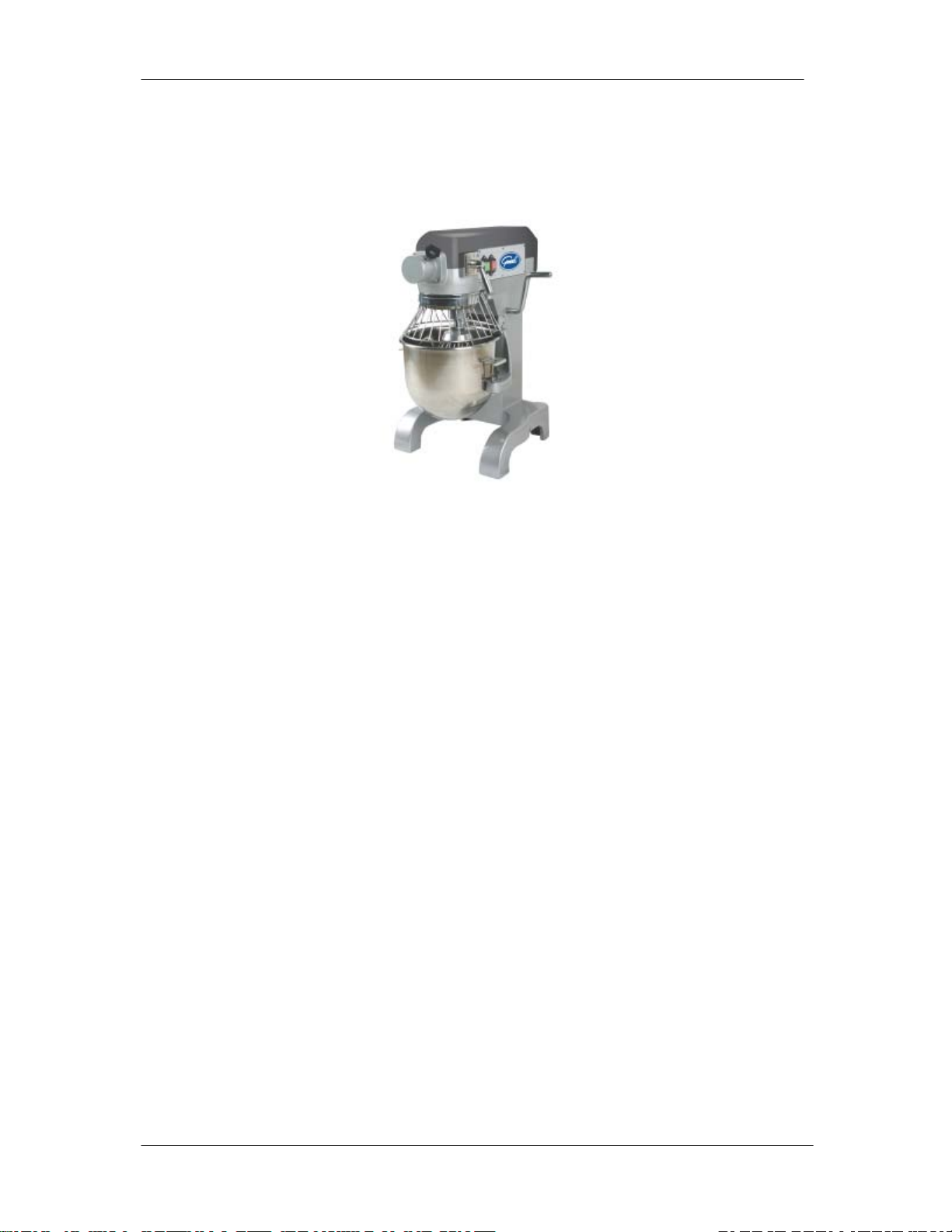
1、 General Description
This is a kind of three-speed gear mixer. With its planetary stirring design, it
has a compact structure, high efficiency, power saving and easy operation. It
will be provided to you as an ideal assistant for bread and cake making.
Page 1 of 1
Page 3
G E M110 Mixer operation instruction edition a
2 Technical parameters
Name Barrel
Volume
(L)
SM-10 10 0.5 75 108 195 355
Power
(KW)
Weight
(Kg)
Speed Of Stirring Shaft
(r/min)
2ndSpeed 3
rd
Speed
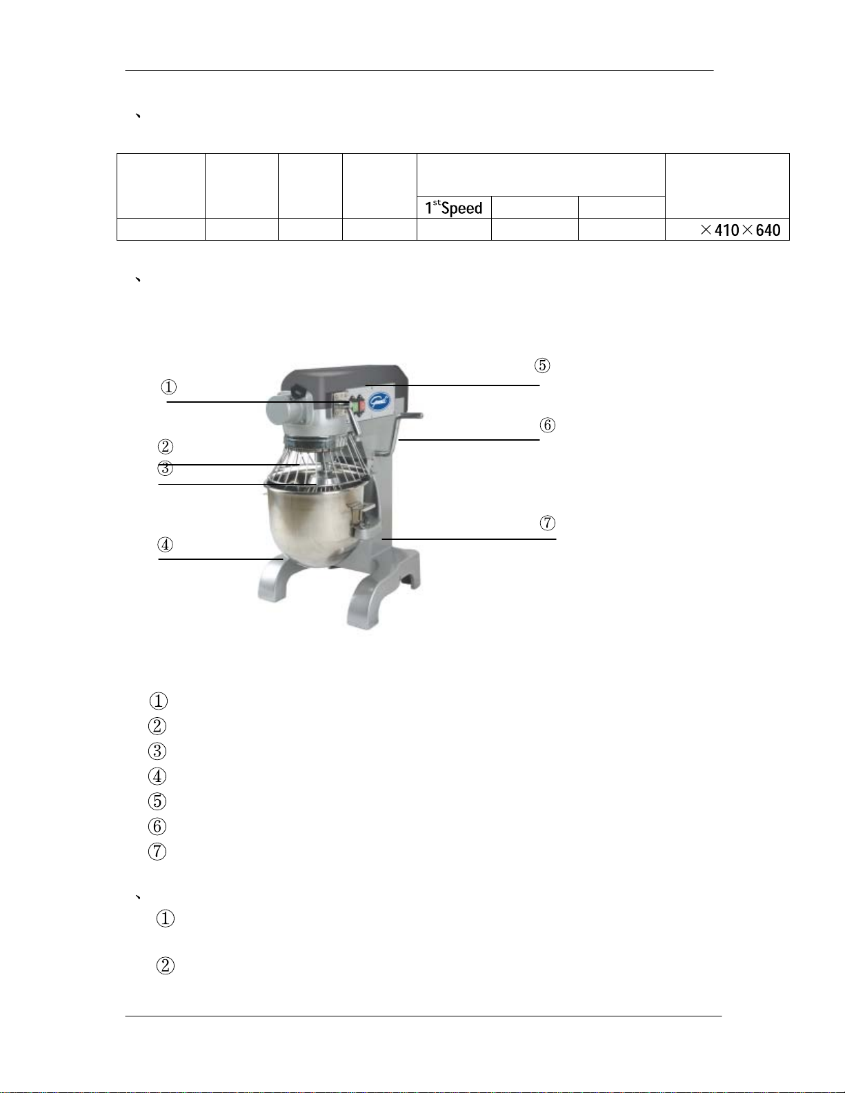
3 Main External Parts of Mixer
.
.
Overall
Dimensions
(mm)
490
Gear change hand lever
Stirring shaft
Mixer
Stainless bowl
Power switch
Bent lever
Support
Operation Instruction
4
Standard power supply 110V/60Hz AC.(Please use a plug with 3
wide contacts and good grounding.)
Installation of Mixer: Put the stirring shaft 2 in Mixer 3 and rotate it
Page 2 of 2
Page 4

GEM110 Mixer operation instruction edition a
in clockwise direction.
③ Starting procedure: Pull the gear change hand lever 1 to position 1
before staring, Safe hood is in closed state. Then turn on the power
switch 5, after the mixer is in normal operation ,set the speed required.
④ Speed transformation: If you want to change the speed, please pull
the bent lever 6 to the lowest point ,after pull the gear change hand lever
1 to the position required, then pull the bent lever 6 to the highest point
and lift the support 7 to the highest position. The machine can be in
normal operation at this time.
⑤ Installation procedures for meat Mincer head : stop operation
first ,loose stud bolt and lift the top cover of its head. Then put on the
st
mincer and tighten the stud bolt.1
speed should be used for mincing
meat.
⑥Shutting down: When the operation is completed, turn off the power
switch 5 first, then pull the gear change hand lever 1 to position 1, and
pull back the hand lever 6 to the lowest point and finally disconnect
power supply.
5、Accessories and Functions
① Spherical mixer: Used for stirring of liquid materials, such as cream
and egg.
② Plate mixer: Used for stirring of paste, powder, and fragmental
materials, such as stuffing.
③ Hook mixer: Used for stirring of more sticky materials, such as
dough .
6、Notes
① The power socket must be provided with a good ground wire to
guarantee the mixer’s good grounding through it. There will be a electric
shock if no ground wire or an improper grounding mounted. The ground
wire can never be connected with gas pipe, water pipe, lightning rod or
telephone line. Electric leakage should be checked after installation.
② Don’t put your hand into the stirring barrel during operation. Power
supply should be disconnected before the mixer is going to be installed.
③ Don’t operate the mixer beyond the time limit to prevent reduction
of its service life.
④ The mixer should be mounted on a stable and clean place. Keep it
away from overheated or overwet places and away from equipment
which has strong electromagnet or can produce strong electromagnet.
⑤ Keep the machine clean constantly. Disconnect power supply before
Page 3 of 3
Page 5

GEM110 Mixer operation instruction edition a
maintenance. Clean it with a piece of soft and a bit wet cloth. Don’t
clean it with liquid or spraying detergent
*** Warning: Do not use medium or high speed for kneading dough.
7、 Maintenances
a. After using, you should clean the bowl and agitator ect, make sure to
keep the machine clean.
b. The transmission gear box is packed with special grease, it could be used
for six mouths in normal condition. If it need to add or replace the
grease, please open the top cover ,then pour the grease from aperture or
replace the grease directly.
8、Problems and solutions
Problems Causes Solutions
The mixing shaft doesn’t
rotate after starting the
Electric connectors are
loose
machine
Oil leakage The oil seals are worn
out
Too low voltage
The temperature of the motor
becomes higher and the
Over-load Lessen the quantity
rotating speed becomes
lower
The speed of mixing is
too high or the mixing
is not suitable
The mixing knocks with the
bowl
The noise of the gearbox is
serious, its temperature is too
The mixing or the
bowl is deformed
Lubrication is
insufficient
high
Check the electric
circuit, tighten
those loose
connects
Replace those oil
seals
Check the power
supply
of the mixture
Select a suitable
speed and mixing
repair or replace the
mixing or bowl
Add or replace the
grease
9. exploded assembly drawing
Page 4 of 4
Page 6

GEM110 Mixer operation instruction edition a
10. electrical diagram
Page 5 of 5
Page 7

GEM110 Mixer operation instruction edition a
7
8
SER.NO. PART.NO. PART NAME
1
2
3
4
5
6
7
8
9
SM10-DQ-01 Distance switch
SM10-DQ-02 Power cord
SM10-DQ-03 Contact switch
SM10-DQ-04 Green button
SM10-DQ-05 Red Button
SM10-DQ-06 Overload switch
SM10-DQ-07 Capacitor100uf
SM10-DQ-08 Capacitor 20 uf
SM10-DQ-09
motor
11. list of part number
Page 6 of 6
Page 8

GEM110 Mixer operation instruction edition a
SM-10 Mixer Spare Parts List
SER.NO. PART.NO. PART NAME Remark SER.N
O.
1 SM10-01-06
2 GB6171-M14x1.5
3 GB9385-14
4 6003
5 SM10-01-07
6 SM10-01-05-01
7 SM10-01-05-03 Taper gear wheel 50 SM20-01-38 Locking bolt
8 SM10-01-05-02
9 SM10-01-05-11
10 SM10-01-05-04
11 SM10-01-05-06
12 SM10-01-05-05
13 SM10-01-05-09
14 SM10-01-18-03
15 SM10-01-18-04
16 SM10-01-18-02
17 SM10-01-05-06
18 SM10-01-05-07
19 6204
20 HG692-25x47x7
21 6001
22 SM10-01-03-01
23 SM10-01-03-02
24 6001
25 GB6171-M14x1.5
26 GB6171-M10x1
27 6001
28 SM10-01-04-01
29 SM10-06-03-00
30 SM10-01-04-02
31 SM10-01-04-05
32 SM10-01-04-03
33 6001
34 SM10-06-02
35 SM10-06-01 Flat Beater 78 GB879-5x30 Pin
36 SM10-05-00 Bowl assembly 79 SM10-03-02-00Z Bowl hold kits
37 SM10-01-18-03
38 SM10-01-18-04 Spring 101 SM10-DQ-01 Distance switch
39 SM10-01-18-02
40 SM10-01-18-01
41 SM10-01-17
42 GB6170-M8
43 SM10-01-02
Top cover
Nut
Clamp plate
Bearing
Transmission
shaft support 48 SM20-01-01 Back Cover
Spacer-lower
Tooth gear
Gear
Gear
Bushing
Sleeve
Main shaft
Plunger-sgifter
yoke
Spring
Retainer-spring
Bushing
Gear
Bearing
Oil seal
Bearing
Shaft worm gear
Gear
Bearing
Nut
Nut
Bearing
Gear shaft
Wire whip
Gear
Bushing
Gear
Bearing
Spiral dough
hook 77 SM10-04-13
Plunger-shifter
yoke
Retainer-spring
Shifting yoke
Declutch shift
shaft 104 SM10-DQ-04 Green button
Nut
Case
44 SM10-01-19
45 GB879-6x30 Pin
46 SM10-DQ-09 Motor
47 SM10-01-01
49 SM10-01-25 Plug
51 SM10-01-11 Attachment hub
52 SM10-01-08
53 SM10-01-09 Taper gear wheel 2
54 SM10-01-13 Front Housing
55 SM10-01-14
56 SM15-02-15
57 SM15-03-00 Safety guard
58 GB894.1-15
59 SM10-01-15-03
60 6202
61 SM10-04-03
62 SM10-01-15-02
63 SM10-01-15-01
64 6203
65 HG692-20x40x7
66 SM10-01-16-01
67 SM10-01-16-02
68 SM10-01-16-06
69 SM10-04-01
70 SM10-04-04
71 SM10-04-12
72 GB848-14
73 GB848-10
74 SM10-04-10
75 SM10-04-08
76 GB6170-M10
80 SM10-03-02-00Y Bowl hold kits
102 SM10-DQ-02 Power cord
103 SM10-DQ-03 Contact switch
105 SM10-DQ-05 Red Button
106 SM10-DQ-06 Overload switch
107 SM10-DQ-07 Capacitor 100uf
108 SM10-DQ-08 Capacitor 20 uf
PART.NO. PART NAME Remark
Worm wheel
Back housing
Ring
Internal gear
Hood ring
Circlips for shaft
Gear
Bearing
Support
Operating shelf
Working shaft
Bearing
Oil seal
Cam-gear shifter
Plate-shifter index
Handle-shifter
Stud
Base
Crank lever
Ring
Ring
Connecting rod
Spring
Nut
Lift handle
Page 7 of 7
 Loading...