

Page 1
OPERATOR'S MANUAL
General Description
3
Cleaning
4
Electrical Requirements
7
Maintenance
11
Parts Replacement
and Service
12
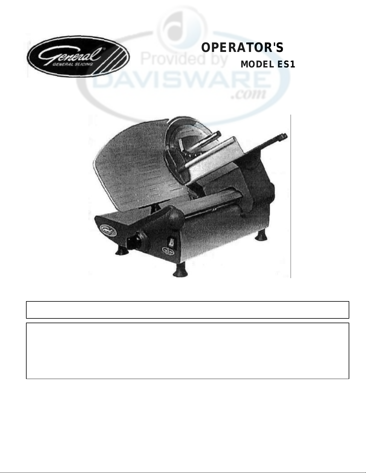
MODEL ES12L SLICER
INTRODUCTION
The Model ES12L Slicer is designed for counter top use. It slices boneless products such as ham, poultry, beef and
cheese to desired thickness.
IMPORTANT: READ THIS MANUAL BEFORE USING THE SLICER.
It is important to read this manual thoroughly before using the slicer. This will help you obtain the full benefits of the
quality, convenience and safety built into this product. Used and maintained according to the following instructions,
the slicer will provide years of trouble-free service. Keep this booklet in a convenient location for future reference.
Safety
Unpacking 4
2
Operation 8
Lubrication 10
Page 2

SAFETY
RECOGNIZE SAFETY INFORMATION. This is the safety-alert symbol.
When you see this symbol on your machine or in this manual, be alert to
the potential for personal injury.
Follow the recommended precautions and safe operating practices.
UNDERSTAND SIGNAL WORDS. Signal words (DANGER, WARNING
and CAUTION) appear with the safety-alert symbol in this manual and on
safety labels on the machine to identify the level of hazard seriousness.
DAN GER indicates a hazard that WILL result in severe personal injury or
death.
WARNING indicates a hazard or unsafe practice which COULD result in
severe personal injury or death.
CAUTION indicates hazards or unsafe practices which COULD result in
minor personal injury or equipment damage.
READ ALL INSTRUCTIONS
Read this operator's manual before using the machine. Failure to follow
the instructions provided could result in personal injury or equipment
damage.
KEEP OUT OF REACH OF CHILDREN
This slicer is intended for commercial use only.
DO NOT OPERATE WITHOUT KNIFE COVER. Do not turn the machine
on unless the knife cover is in place.
DO NOT FEED FOOD BY HAND. Always use the foodpusher.
KEEP HANDS AWAY FROM KNIFE. Never touch the knife with your hand.
DO NOT CATCH FOOD WITH YOUR HANDS. Let sliced food fall onto the
receiving area.
DO NOT OPERATE IF DAMAGED. Do not operate this slicer with a
damaged cord or plug, or if the slicer has been dropped or damaged in any
manner. Contact the nearest factory-authorized service center for
examination, repair or adjustment. (Refer to the service center list included
in the Owner's Information Packet.)
Do not allow the cord to touch hot surfaces. Do not allow the cord to hang
over the edge of a table or counter.
DO NOT LEAVE SLICER UNATTENDED. Never leave the slicer
unattended while the unit is operating.
UNPLUG SLICER. Set the regulator knob to "0" and unplug the slicer from
the outlet when not in use, before cleaning or removing jams, and before
attaching or removing this knife sharpener.
DO NOT IMMERSE
Do not place the slicer in water or any other liquid.
ATTACHMENTS
Do not use attachments not recommended by the manufacturer.
Follow the manufacturer's instructions for use of attachments.
SAVE THESE INSTRUCTIONS
Keep this manual in a convenient location for future reference.
2
Page 3
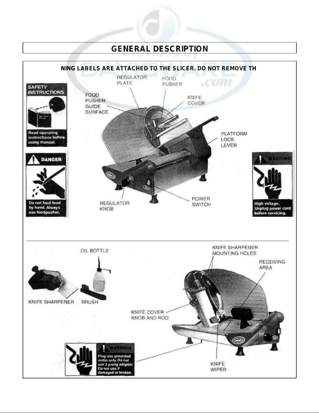
GENERAL DESCRIPTION
THESE WARNING LABELS ARE ATTACHED TO THE SLICER. DO NOT REMOVE THEM.
3
Page 4
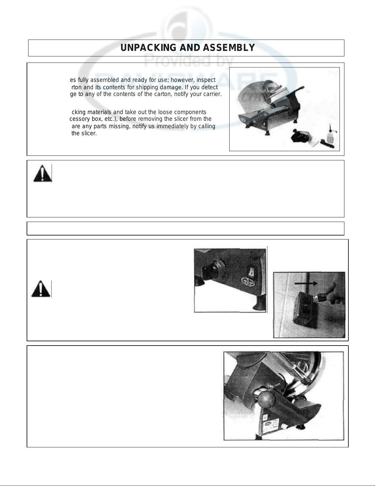
UNPACKING AND ASSEMBLY
UNPACKING
The slicer comes fully assembled and ready for use; however, inspect
the shipping carton and its contents for shipping damage. If you detect
shipping damage to any of the contents of the carton, notify your carrier.
Remove the packing materials and take out the loose components
(sharpener, accessory box, etc.), before removing the slicer from the
carton. If there are any parts missing, notify us immediately by calling
the number on the slicer.
CAUTION: The slicer should be installed on a level counter
top strong enough to safely support its weight.
The slicer should be thoroughly cleaned and sanitized (See below) before using to
ensure sanitary conditions.
CLEANING
Clean and sanitize the slicer before using the first time,
after each use, and before slicing different types of food
products. Follow company, local, and state
health/sanitation codes.
WARNING: Set the regulator knob to "0" and
unplug the slicer before cleaning or handling.
Do NOT use caustic or abrasive cleaners.
Do NOT spray cleaning materials or water toward the
power switch, the regulator knob, or the openings of the
machine.
DISASSEMBLY FOR CLEANING
Platform Assembly
1. Rotate cam lock lever clockwise.
4
Page 5

2.
Pull off platform and food pusher assembly.
CLEANING (continued)
Knife Wiper
1. Remove the thumbscrew by turning counter-clockwise.
2. Remove the knife wiper.
Knife Cover
1. Loose n the knife cover knob and rod assembly by turning it 2 turns
counter-clockwise.
2. Push the knob and rod assembly in against the knife cover to dislodge it.
3. Support the knife cover with the left hand.
4. Unscrew and remove the knob and rod assembly by continuing to turn it
counter-clockwise.
5. Remove the knife cover.
CAUTION: Always use protective cut -resistant gloves when
knife is exposed.
5
Page 6

CLEANING (continued)
WASH ALL SURFACES
1. Clean all surfaces and parts of the slicer with hot, soapy water and a
clean cloth.
2. Clean the foodpusher shaft to remove food juices and ensure smoot h
operation.
3. Clean the knife front and back with hot, soapy water and a clean cloth
by wiping outward from the center.
REASSEMBLY
Knife Wiper
1. Re-install the knife wiper by positioning it as close to the knife as
possible (the wiper should not touch the knife). Replace and
tighten the thumbscrew.
Knife Cover
1. Re-install the knife cover by positioning the space on the back
of the knife cover in the center of the knife hub.
Note: The grooves on the front of the knife cover should be
horizontal, as on the regulator plate.
2. Replace the knob and rod assembly, and tighten by turning it
clockwise.
6
Page 7

2.
Rotate cam lock level counter
-
clockwise until tight.
CLEANING (continued)
Platform Assembly
1. Slide on platform and food pusher assembly until positive stop is
reached.
ELECTRICAL REQUIREMENTS
Use a properly grounded three-prong outlet to reduce the hazard of
electrical shock.
The slicer should be placed close enough to the electrical power supply
so that an extension cord will not be needed. It is designed to be used
on 115 Volt, A.C., 60 Hz power source, as indicated on the Data Plate
affixed to the back of the unit. Be sure that the voltage is the same
before plugging the slicer into the outlet. To operate the unit on other
voltages, the slicer must be returned to the factory for modification.
All electrical connections must be made in compliance with all
applicable local electrical codes, as well as the latest edition of the
National Electrical Code (NFPA 70).
7
Page 8

OPERATION
Clean and sanitize the slicer before using the first time, after each
use, and before slicing different types of food products. Follow
company, local, and state health/sanitation codes. (See Page 4.)
CAUTION: Do not cut products that contain bone or frozen
product.
1. Plug the power cord into a grounded three-prong outlet. (See
Electrical Requirements, Page 7).
2. Pull the platform assembly to the front of the slicer (toward you).
3. Raise the foodpusher to its open position.
4. Place the product to be sliced on the platform against the
regulator plate and lower the foodpusher against the product.
5. Set the regulator knob to the desired slice thickness.
8
Page 9

6. Set the power switch to ON. (I)
OPERATION (continued)
DANGER: Do not feed food by hand. Always use the
foodpusher.
DANGER: Keep your hands away from the back of the
cutting edge of the knife.
7. Holding the food pusher handle with your right hand, move the
platform forward to complete the slice, and back until the product
clears the cutting edge of the knife. Repeat until desired quantity
is cut. (The slicer is gravity-fed, so it is not necessary to exert
force or pressure against the foodpusher.)
8. Set the power switch to OFF (0), turn the regulator knob to
"0", and unplug the slicer.
Clean the slicer after each operation, as described in the
Cleaning Section.
9
Page 10

2.
Remove platform.
LUBRICATION
To ensure continued smooth operation of sliding parts, use the oil
supplied in the accessory box or a light non-toxic mineral oil.
1. Apply 2-3 drops of oil to the foodpusher glide surface after each
cleaning.
2. Apply 1-2 drops of oil to the knife cover rod threads after each
cleaning.
MAINTENANCE
SHARPENING THE KNIFE
CAUTION: Always use protective cut -resistant gloves when
attaching or removing the sharpener, as this will leave a
portion of the knife exposed. Do not touch expos ed knife
edge.
Note: Inspect the sharpening stones to be sure they are clean and free of
cracks or chips. Clean, if necessary, with the wire brush provided.
Replace the stones if they are cracked or chipped.
1. Clean the knife, as described in the Cleaning Section, to remove all
food particles and grease.
3. Set the regulator knob to "15".
10
Page 11

4.
Remove the sharpener lock knob from the sharpener by
MAINTENANCE (continued)
turning it counter-clockwise.
5. Holding the sharpener by the housing base, attach it to the front
of the regulator plate with the alignment pin in the hole closest to
the knife.
6. Screw the sharpener lock knob through the back of the
regulator plate into the sharpener by turning it clockwise.
7. Set the power switch to ON (I).
8. Turn the regulator knob to "12" for 5 seconds.
9. Turn the regulator knob to "17" for 2-3 seconds.
10. Set the regulator knob back to "15".
11. Set the power switch to OFF (0) and unplug the slicer.
11
Page 12

12
Remove the sharpener and replace the
sharpener lock knob in the sharpener.
13
Set the regulator knob to "O".
MAINTENANCE (continued)
14
Clean both sharpening and deburring stones with the wire brush.
15
Remove the knife cover and clean the knife, as described in the
Cleaning Section.
16
Remove and clean the knife wiper, as described in the Cleaning
Section.
NOTE: Before slicing again be sure that all steel particles from grinding have
been removed to prevent contamination of food.
PARTS REPLACEMENT AND SERVICE
PARTS REPLACEMENT
Use the replacement parts list and the parts distributors list included in
the Owner's Information Packet to order spare parts. Specify the part
number and part name.
SERVICE CENTER LIST
For repair consult the factory -authorized service center list included in the
Owner's Information Packet for the closest service center.
12
Page 13

KEY
QTY
2
3
4
5
6
7
8
08-SM-1080 NUT: HEX
6MM 3
8a
8b
8c
9
10
09-SM-6316 SPRING: SHORT
1 11
12
13
14
08-SM-6196 NUT: JAM HEX 3MM
2 15
16
23-SM-6323 PLATFORM
1
17
09-SM-6324 GUARD: PLATFORM KNIFE
1 18
19
09-SM-6326 HANDLE: FOOD PUSHER
1
20
21
09-SM-6327 SHAFT: FOOD PUSHER
1 22
23
24
25
09-SM-6331 CLIP: REGULATOR BRKT
1
25c 08-SM-1080 NUT: HEX
6MM 2
26
27
27a 08-SM-6127 WASHER: STAR 5MM
2
28
08-SM-1761 SCREW: HXHD 8MA X
35
BRASS
2
29
30
30d 08-SM-1055 WASHER: FLAT
6MM 1
31
32
33
34
35
36
37
38
39
40
23-SM-6344 REGULATOR PLATE
1 41
43
44
KEY
45 09-SM-6348 WEAR ST
RIP: PLATFORM ROLLER
1
46
46a 08-SM-1010 WASHER: FLAT
8MM 2 46b 08-SM-1515 NUT: HEX
8MM 2
47
48
48a 08-SM-6377 S
CREW: SET
4MA X 4 4
49
50
54
55 23-SM-6356 BODY PANEL: CARRIAGE SIDE.
1 57
58
08-SM-6380 SCREW: SET 5MA X
20 4
59
60
61
62
05-SM-1894 BUSHING: STRAIN RELIEF
1 63
64
65
08-SM-1514 WASHER: STAR
8MM 1
66
05-SM-6304 CAPACITOR: 20UF/
450V;
ES12L
1
67
68
69
70
71
72
09-SM-6361 SHELF: KNIFE BACK
1 73
74
75
76
08-SM-1340 SPACER: KNIFE PULLEY SHAFT
1 79
80
09-SM-6364 SPRING SHARPENING STONE
1
81
82
83
84
09-SM-6367 SPRING: DEBURRING STONE
1 85
86
87
88
89
90
91
92
93
09-SM-6372 ROD: THREADED
& FORMED
1 94
95
Effective: April
1, 1999
REPLACEMENT PARTS LIST
MODEL: ES12L
NO.
1 09-SM-6308 BRACKET: PLATFORM 1
13a 08-SM-6320 SCREW: PNHD 3MAX 45 2
19a 08-SM-1264 SOCKET SET SCREW: M10 X 2 1
25a 08-SM-6373 SCREW: HXHD 6MAX 60 2
25b 08-SM-6076 WASHER: STAR 6MM 2
27b 08-SM-1073 SCREW: HXHD 5MAX10 2
28a 08-SM-1515 NUT: HEX 8MM 2
29a 08-SM-6118 SCREW: SET 5MAX 6 2
30a 08-SM-6374 SCREW: SOC HD 5MAX 10 4
30b 08-SM-6076 WASHER: STAR 6MM 2
30c 08-SM-6101 SCREW: SOC HD 6MAX 15 1
30e 09-SM-6336 SPACER, REG BKT HSG 1
42 23-SM-6345 SUPPORT: REGULATOR PLATE 1
PART NO.
09-SM-6309 BLOCK: CAM LOCK 1
06-SM-6310 ROLLER: PLATFORM BRACKET 2
09-SM-6311 SHAFT: ROLLER 2
08-SM-1055 WASHER: FLAT 6MM 6
08-SM-6312 RETAINING RING: EXTERNAL 1
30-SM-6313 CAM ASSY (INC: 6 & 7) 1
06-SM-6314 GLIDE: NYLON 1
08-SM-1515 NUT: HEX 8MM 2
08-SM-6076 WASHER: STAR 6MM 1
09-SM-6315 SPRING: LONG 1
01-SM-6317 PLATFORM: CARRIAGE 1
09-SM-6318 SHAFT: PLATFORM CARRIAGE 1
09-SM-6319 BLOCK: SHAFT RETAINING 2
09-SM-6322 CAP: PLATFORM (LEFT) 1
30-SM-6323 PLATFORM ASSY (INC: 13-23, 32 & 33)
09-SM-6325 CAP: PLATFORM (RIGHT) 1
23-SM-6307 FOOD PUSHER W/SPIKES 1
30-SM-6307 FOOD PUSHER ASSY (INC: 19-23)
06-SM-6328 NYLON RIDER: FOOD PUSHER 1
09-SM-6384 BUMPER: FOOD PUSHER 1
09-SM-6330 SPRING, REGULATOR TENSION 1
09-SM-6332 REGULATOR BRKT 1
04-SM-6333 ROD: REG BRKT SPANNER 1
09-SM-6334 REGULATOR CAM 1
09-SM-6335 HOUSING: REG BRKT 1
05-SM-6337 SWITCH: ROCKER 1
08-SM-6375 SCREW: PHL PNHD 4MA X 15 ST 25
09-SM-6338 PLUG: SCREW COVER 25
09-SM-6339 PLUG: SCREW COVER 2
08-SM-6340 SCREW: CSK SOC HD 8MAX 25 2
09-SM-6321 LENS: KNOB NUMBER 1
09-SM-6341 REGULATOR KNOB 1
08-SM-6342 WASHER: REGULATOR KNOB 1
09-SM-6343 CAP: SHELF END (LEFT) 1
09-SM-6128 KNOB & ROD ASSY: SHARPENER ATTACH 1
06-SM-6346 BOOT: REG PL SUPPORT 1
23-SM-6347 BODY: CENTER SECTION 1
NAME: DESCRIPTION MACH
NO.
49a 08-SM-6378 SCREW: KNIFE WIPER 1
51 09-SM-6353 SUPPORT: KNIFE GUARD STANDOFF (TOP) 1
52 09-SM-6354 STANDOFF: KNIFE GUARD (RIGHT) 1
53 09-SM-6301 KNOB & ROD ASSY: KNIFE COVER 1
65a 08-SM-1515 NUT: HEX 8MA 1
80a 08-SM-1055 WASHER: SPRING STOP 1
81 a 09-SM-6365 GUARD: SHARPENER 1
81 b 08-SM-6381 SCREW: CSK PHLHD 4MAX 10 ST 1
86a 08-SM-6363 WASHER: FIBER 6MM 2
86b 08-SM-1016 NUT: JAM HEX 6MA 2
90a 08-SM-1055 WASHER: FLAT 6MM 7
90b 08-SM-1080 NUT: HEX 6MM 7
95a 08-SM-1055 WASHER: FLAT 6MM 2
General Slicing/Red Goat Disposers • 1152 Park Avenue • P.O. Box 428 • Murfreesboro, TN 37133-0428 • (615) 893-4820
PART NO.
09-SM-6349 CAP: SCREW (REG PL SUPPORT) 1
09-SM-6350 STANDOFF: KNIFE GUARD (STRAIGHT) 2
09-SM-6351 SUPPORT: KNIFE GUARD STANDOFF (LEFT) 1
09-SM-6306 KNIFE WIPER 1
09-SM-6352 STANDOFF: KNIFE GUARD (TOP) 1
09-SM-6355 SUPPORT: KNIFE GUARD STANDOFF (RIGHT) 1
08-SM-6379 BUSHING: EXPANSION 5MM BRASS 4
06-SM-1463 FOOT: 45MM HW/6MA STUD 4
23-SM-6357 SHELF SECTION 1
09-SM-6358 CAP: SHELF END (RIGHT) 1
05-GSM-756 CORDSET 1
09-SM-6359 PLATE: MOTOR MTG 1
05-SM-6384 CAPACITOR: 8UF/450V; ES12H 1
30-SM-6136 MOTOR ASSY: 115V/60HZ; ES12L 1
30-SM-6376 MOTOR ASSY: 220V/50/60H; ES12H 1
23-SM-6302 KNIFE COVER 1
08-SM-1032 SCREW: CSK HD 5MA SS 3
09-SM-6001 KNIFE: 12" 1
09-SM-6360 KNIFE GUARD 1
06-SM-6305 BELT: TB2-34-660 1
30-SM-6362 KNIFE PULLEY ASSY 1
08-SM-1218 SPACER: KNIFE PULLEY 2.3MM 1
30-SM-6060 KNIFE SHARPENER ASSY (INC: 79-86b) 1
08-SM-1021 RING: RETAINING 2
09-SM-6366 SHAFT: SHARPENING STONE 1
09-SM-850 STONE: SHARPENING 1
09-SM-6368 SHAFT: DEBURRING STONE 1
09-SM-851 STONE: DEBURRING 1
23-SM-6369 BACK SUPPORT 1
08-SM-1217 WASHER: FLAT 14MM X 1 1
08-SM-1216 NUT: HEX 14MM X 1 1
08-SM-6382 SCREW: SOC HD 6MAX 35 2
09-SM-6370 BOTTOM COVER 1
09-SM-6371 BLOCK: MOTOR MOUNT 1
08-SM-6383 NUT: HEX NYLOC 6MM 2
08-SM-6090 SCREW: HEXHD 8MA X 45 2
QTY
NAME: DESCRIPTION MACH
Page 14

MODEL ES12L
 Loading...