

Page 1
RED GOAT DISPOSERS
Installation • Operation • Maintenance
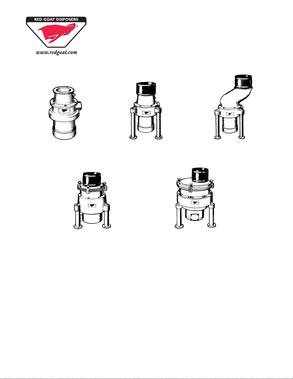
“H” Series “A” Series “A” Offset
“B” Series “C” Series
Ordering Instructions.......................................2
Safety..............................................................3
General Installation .........................................4
“H” Series Installation & Connection...............5
“A” Series Installation & Connection ...............6
“B” Series Installation & Connection ...............7
“C” Series Installation & Connection...............8
Typical Installation/Start-up & Run..................9
Operation/Troubleshooting............................10
Troubleshooting.............................................11
Red Goat Disposers
165 Independence Court • Lancaster, PA 17601
800.237.6628 • 717.397.5100 • FAX 717.397.1997
www.redgoat.com Red Goat Disposers 10/12
Maintenance .................................................12
Parts Replacement .......................................14
Motor Test Results ........................................15
“H” Replacement Parts .................................16
“A” Replacement Parts .................................18
“B” Replacement Parts .................................20
“C” Replacement Parts .................................22
“RAC1” Replacement Parts ..........................24
“RAC2” Replacement Parts ..........................25
Hostile Environment Table/Disposer.............26
Terms of Sale and Warranty..........................28
Page 2

ORDERING INSTRUCTIONS
Contact the Factory-authorized Parts Distributor for all parts orders or contact us directly for the name and phone
number of the parts distributor nearest you:
Call Toll Free: 800-237-6628
FAX: 717-397-1997
Page 2 Red Goat Disposers 10/12
Page 3
SAFETY
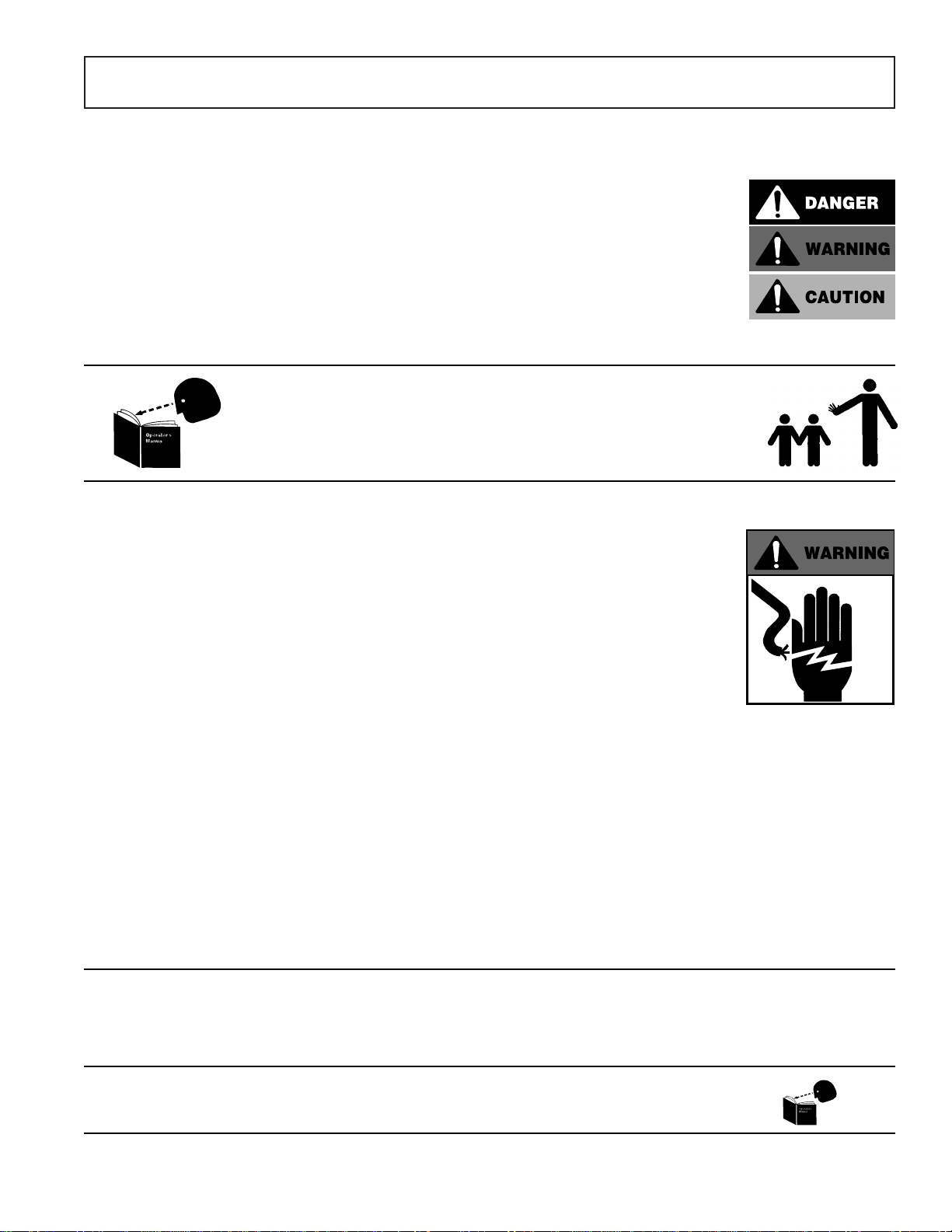
RECOGNIZE SAFETY INFORMATION. When you see this symbol on
your machine or in this manual, be alert to the potential for personal
injury.
UNDERSTAND SIGNAL WORDS. DANGER, WARNING and CAUTION
appear with the safety-alert symbol in this manual and on safety labels on
the machine to identify the level of hazard seriousness.
DANGER indicates a hazard that WILL result in severe personal injury or
death.
WARNING indicates a hazard or unsafe practice which COULD result in
severe personal injury or death.
CAUTION indicates a hazard or unsafe practice which COULD result in
minor personal injury or equipment damage.
READ ALL INSTRUCTIONS
Read this owner’s manual before using the machine. Failure to follow the
instructions provided could result in personal injury or equipment damage.
KEEP OUT OF REACH OF CHILDREN
This disposer is intended for commercial use only.
DO NOT PUT HANDS OR ANY IMPLEMENT IN THE DISPOSER
WHILE IN OPERATION.
NEVER FEED WASTE BY HAND PAST VINYL SILVER TRAP
SCRAPPING RING.
DO NOT OPERATE IF DAMAGED.
Do not install or operate this disposer if the disposer has been dropped
or damaged in any manner. Contact the nearest factory-authorized
service center for examination, repair or adjustment. (Refer to the service
center list included in the Owner ’s Information Packet.)
DO NOT LEAVE DISPOSER UNATTENDED.
SET THE POWER SWITCH TO OFF BEFORE CLEARING JAMS OR
REMOVING OBJECTS FROM DISPOSER.
When the disposer is wired to a Manual Control or Model RAC1 Control
Center, SHUT OFF the branch circuit main switch or disconnect.
When disposer is wired to a RAC2 Control Panel, TURN OFF emergency
disconnect.
Use long-handled tongs or pliers to remove objects.
TO REDUCE THE RISK OF INJURY BY MATERIALS THAT MAY BE
EXPELLED BY DISPOSER, DO NOT PUT THE FOLLOWING INTO
DISPOSER: drain cleaner; glass, china or plastic; large, whole bones;
metal (bottle cas, tin cans, aluminum foil, etc.); whole cornhusks.
ALWAYS KEEP VINYL SILVER TRAP SCRAPPING RING OR SINK
STOPPER IN PLACE ON SERIES “H-RSA”, EVEN WHEN NOT IN USE.
This reduces the risk of objects falling into the disposer .
WHEN CLEANING KITCHEN AND DISPOSER AREA, ONLY DAMP
WIPE OUTSIDE OF DISPOSER AND CONTROLS. DO NOT AT ANY
TIME HOSE DOWN THE EXTERIOR SURF ACES OF THE DISPOSER
AND CONTROLS.
SAVE THESE INSTRUCTIONS.
Keep this booklet in a convenient location for future reference.
Red Goat Disposers 10/12 Page 3
Page 4

GENERAL INSTALLATION
FABRICATING
1. Consult installation and connection data and installation diagrams on following pages for regular cone or regular
sink attachment dishtable cutout sizes.
2. For cone attachment, position cone so water swirl inlet fitting is nearest to operator .
3. Weld the total circumference of cone or sink attachment to prevent leakage.
4. Smooth grind and polish to match and blend weld seams.
NOTE: DO NOT PLACE CONTROL MOUNTING BRACKETS IN DIRECT WATER SPLASH AREAS.
PLUMBING
1. Consult installation and connection data and installation diagrams on following pages for mounting, hookups and
pipe sizes.
2. “H” Series is mounted by suspending from dishtable.
3. “A”, “B” and “C” Series use a floor leg support system with a neoprene connecting sleeve and two (2) stainless
steel clamps. Supplied sleeve (8” length) should be cut to required length for connection of disposer to dishtable.
4. Slide in, or position, disposer to connect to waste line, avoiding as many bends, elbows and tees as possible.
5. Flexible drain connection should be installed as follows:
A. Slip coupling over disposer outlet, then onto drain pipe.
B. Using a 5⁄16” nut driver, tighten to a torque of 60 in-lbs.
6. Perform power-rotor reaming of waste line whether connection is made to a new or old waste line. New lines
often contain foreign items left in the lines accidentally during construction.
7. Blow new water feed lines out before connections are made. Dirt, solder, or other foreign matter can lodge itself
in the flow controls, solenoid valve and vacuum breaker , causing malfunction.
8. Install solenoid valve. Check that inlet and outlet ports are in proper direction.
9. Check that disposer and dishtable opening are in line, level and true. This is visible when neoprene sleeve is
not kinked or partially collapsed. If level and in line adjustment is required, turn feet on bottom of legs.
10. Secure disposer to floor using the holes provided in the feet.
ELECTRICAL
NOTE: FOLLOW GUIDELINES SET FORTH BY NEC STANDARD AND LOCAL CODES.
1. Consult installation and connection data and diagrams on following pages for control placement and motor
wiring.
NOTE: DO NOT PLACE CONTROL IN DIRECT WATER SPLASH AREAS.
2. Follow supplied wiring schematics for all controls, solenoid valves and pre-wired custom control centers.
3. Size and fuse disposer branch circuit or use circuit breakers as required by motor nameplate rating.
4. Check that motor voltage wiring matches incoming voltage.
NOTE: ALL CONDUIT AND FITTINGS SHALL BE OF THE NEMA 4 WATERTIGHT TYPE.
5. All “H” and “A” disposers have thermal protection of the manual reset type, in motor . Check that reset button is
not jammed.
6. All “B” and “C” disposers must have thermal protection (heaters) in control. Check that heaters are sized properly
to prevent either motor burnout or nuisance tripping.
7. Check that all connections are tight, secure and well-grounded.
NOTE: Disposers are designed to operate in both a clockwise and counter-clockwise direction. Direction of rotation
does not have to be considered when wiring motor .
GROUNDING
Connect disposer to a grounded metal permanent wiring system or run a disposer grounding conductor with the circuit
conductors and connect it to the disposer grounding terminal or lead on the disposer .
Page 4 Red Goat Disposers 10/12
Page 5
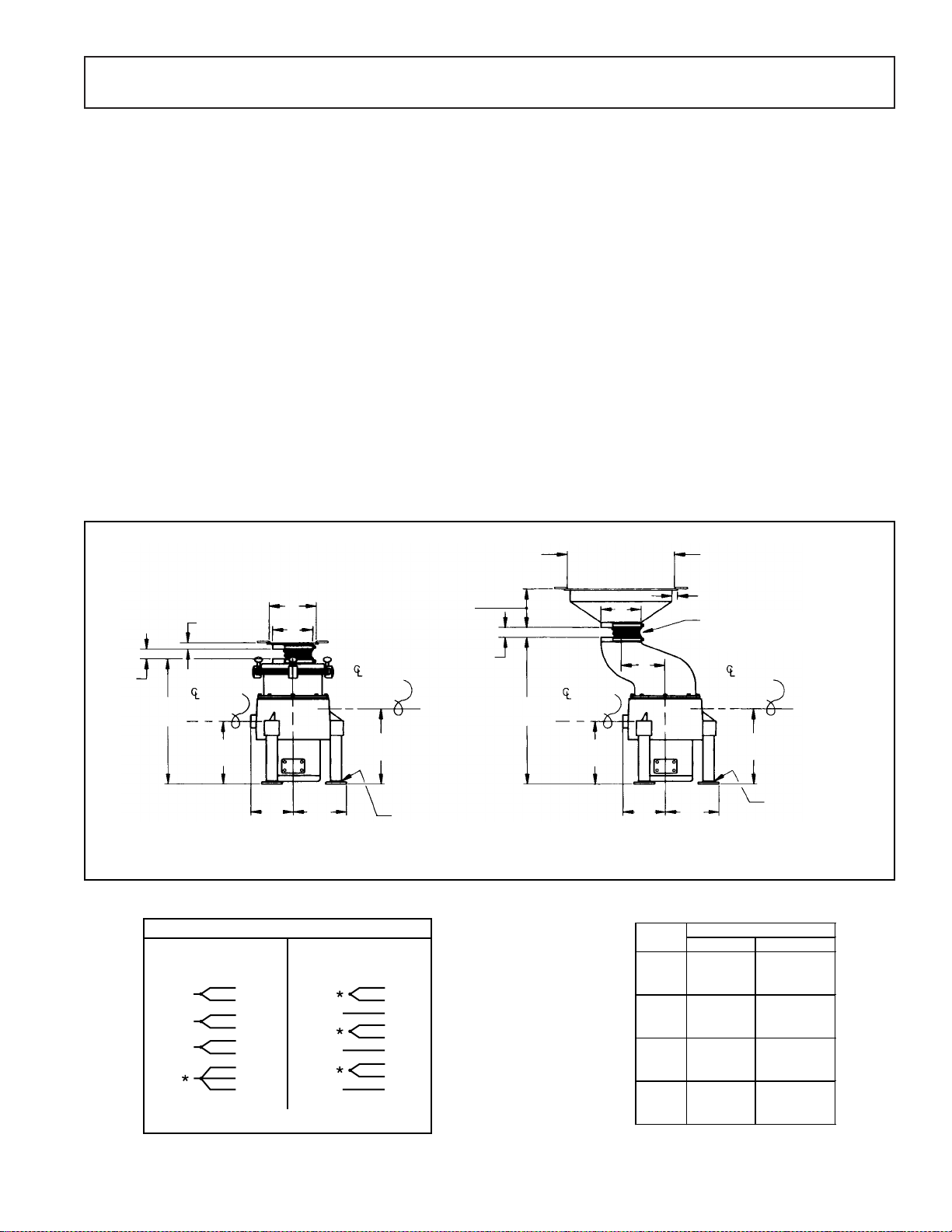
“H” SERIES - Installation and Connection
NOTE: PLUMBING AND ELECTRICAL CONNECTIONS SHALL BE MADE IN COMPLIANCE WITH APPLICABLE
LOCAL CONSTRUCTION CODES.
PLUMBING
Inlet: Cold water supply to disposer shall be 1⁄2" service line with a minimum of 20 lbs. flow pressure, piped as close to
disposer as possible. All disposer and control connections shall be 1⁄2" pipe size.
Sewer Outlet: 11⁄2" waste line should have trap with conveniently located clean out. Do not connect through a grease trap.
Avoid bends, elbows, tees, etc., to reduce the possibility of plumbing stoppage. . A globe valve, used for metering flow, must
be installed between solenoid valve and cone or sink. Water swirl inlet valves should be located nearest operator.
See Typical Installation Diagram.
ELECTRICAL
Follow guidelines set forth by NEC standards. Disposer branch circuit shall be sized and fused (circuit breakers) as
required by motor. The disposer must be connected to a grounded, metal, permanent wiring system; or a disposergrounding conductor must be run with the circuit conductors and connected to the disposer-grounding terminal or lead
on disposer. All connections, junction boxes and conduits must be watertight (NEMA 4).
TESTING See Start-up and Run Section.
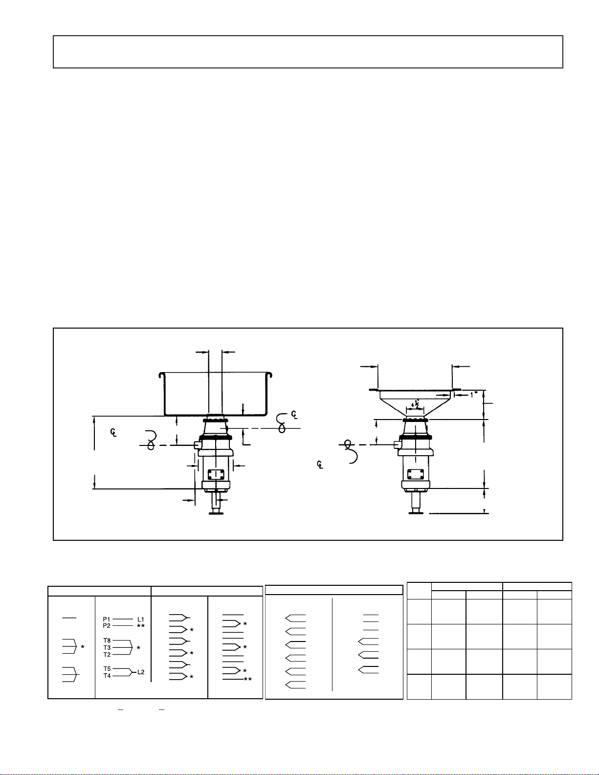
INSTALLATION DIAGRAM
31⁄4” INSIDE
DIAMETER
7
7
DRAIN
SEE SPEC SHEET FOR
MOTOR SPECIFIC SIZES
⁄8”
DISPOSER SHOWN WITH SINK MOUNTING ASSEMBLY DISPOSER SHOWN WITH CONE MOUNTING ASSEMBLY
MOTOR WIRING DIAGRAMS
)RUXVHZLWK/HHVRQPRWRUV
SINGLE PHASE THREE PHASE
115 Volt, 60 Hz 230 Volts, 60 Hz 208/230 Volt, 60 Hz 460 Volt, 60 Hz
110 Volt, 50 Hz 220 Volts, 50 Hz 190-220 Volts, 50 Hz 380-440 Volts, 50 Hz
P1
L1
T8
P2
T3
T5
L2
T2
T4
Tied Together and Insulated
*
Insulated
**
6 = Six 9 = Nine
T1
T7
T4
P4
T2
T8
T5
P5
T3
T9
T6
P6
T1
L1
T7
T4
P4
T2
L2
T8
T5
P5
T3
L3
T9
T6
P6
SINK MOUNTING ASSEMBLY
WILL FIT STANDARD 3
TO 4” DIAMETER OPENING
WATER INLET
1
3
⁄4”
9”
1
5
⁄2”
)RUXVHZLWK%DOGRUPRWRUV
208-230 Volts, 60 Hz
190-220 Volts, 50 Hz
L1
**
L2
**
L3
THREE PHASE WITH THERMAL
L1
L2
L3
*
*
*
Tied Together and Insulated
*
1
⁄2
”
DRAIN
TABLE CUTOUT
13” FOR 12” CONE
16” FOR 15” CONE
19” FOR 18” CONE
5
⁄8”
6
6” FOR 12” CONE
5” FOR 15” CONE
7” FOR 18” CONE
SEE SPEC SHEET FOR
MOTOR SPECIFIC SIZES
65⁄8
”
VOLTAGE-AMPERAGE TABLE
460 Volts, 60 Hz
380 Volts, 50 Hz
1
7
2
8
9
3
10
4
11
5
12
6
L1 1
L2 2
L3 3
4
7
*
5
8
*
6
*
9
**10 **11 **12
Insulated
**
HP Volts Amps* Volts Amps*
3/4
1 1/2
SINGLE PHASE THREE PHASE
115 5.4 208 2.8
230 10.8 230 2.8
460 1.4
115 12.8 208 3.6
1
230 6.4 230 3.6
460 1.8
115 17.2 208 4.9
230 8.6 230 4.4
460 2.2
115 20.0 208 6.9
2
230 10.0 230 6.2
460 3.1
*Ratings are for 60 Hz operation
Red Goat Disposers 10/12
Page 5
Page 6
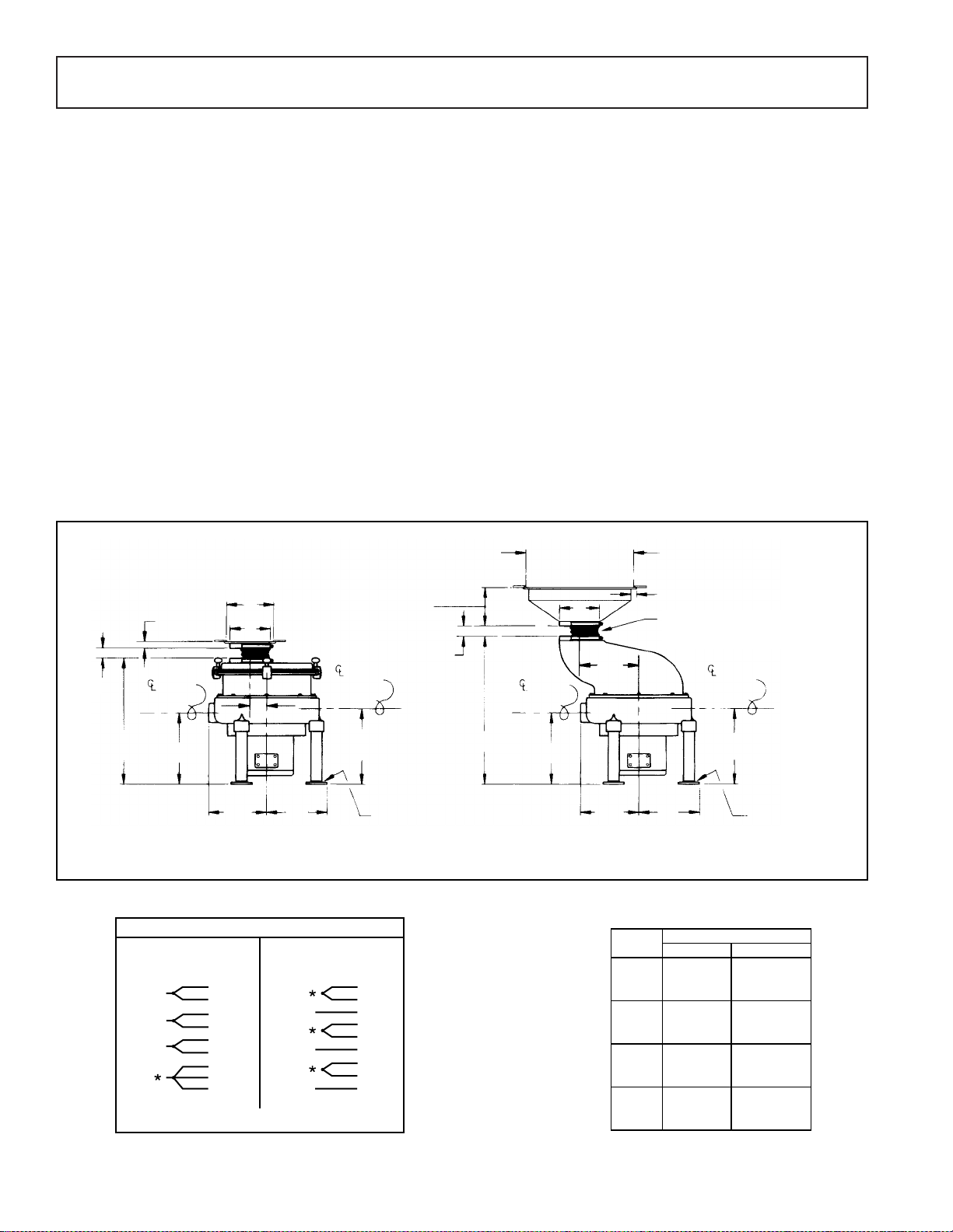
“A” SERIES - Installation and Connection
NOTE: PLUMBING AND ELECTRICAL CONNECTIONS SHALL BE MADE IN COMPLIANCE WITH APPLICABLE
LOCAL CONSTRUCTION CODES.
PLUMBING
Inlet: Cold water supply to disposer shall be 1⁄2" service line with a minimum of 20 lbs. flow pressure, piped as close to
disposer as possible. All disposer and control connections shall be 1⁄2" pipe size.
Sewer Outlet: 2" waste line should have trap with conveniently located clean out. Do not connect through a grease trap.
Avoid bends, elbows, tees, etc., to reduce the possibility of plumbing stoppage. A globe valve, used for metering flow,
must be installed between solenoid valve and cone or sink. Water swirl inlet valves should be located nearest operator.
See Typical Installation Diagram.
ELECTRICAL
Follow guidelines set forth by NEC standards. Disposer branch circuit shall be sized and fused (circuit breakers) as
required by motor. The disposer must be connected to a grounded, metal, permanent wiring system; or a disposergrounding conductor must be run with the circuit conductors and connected to the disposer-grounding terminal or lead
on disposer. All connections, junction boxes and conduits must be watertight (NEMA 4).
TESTING See Start-up and Run Section.
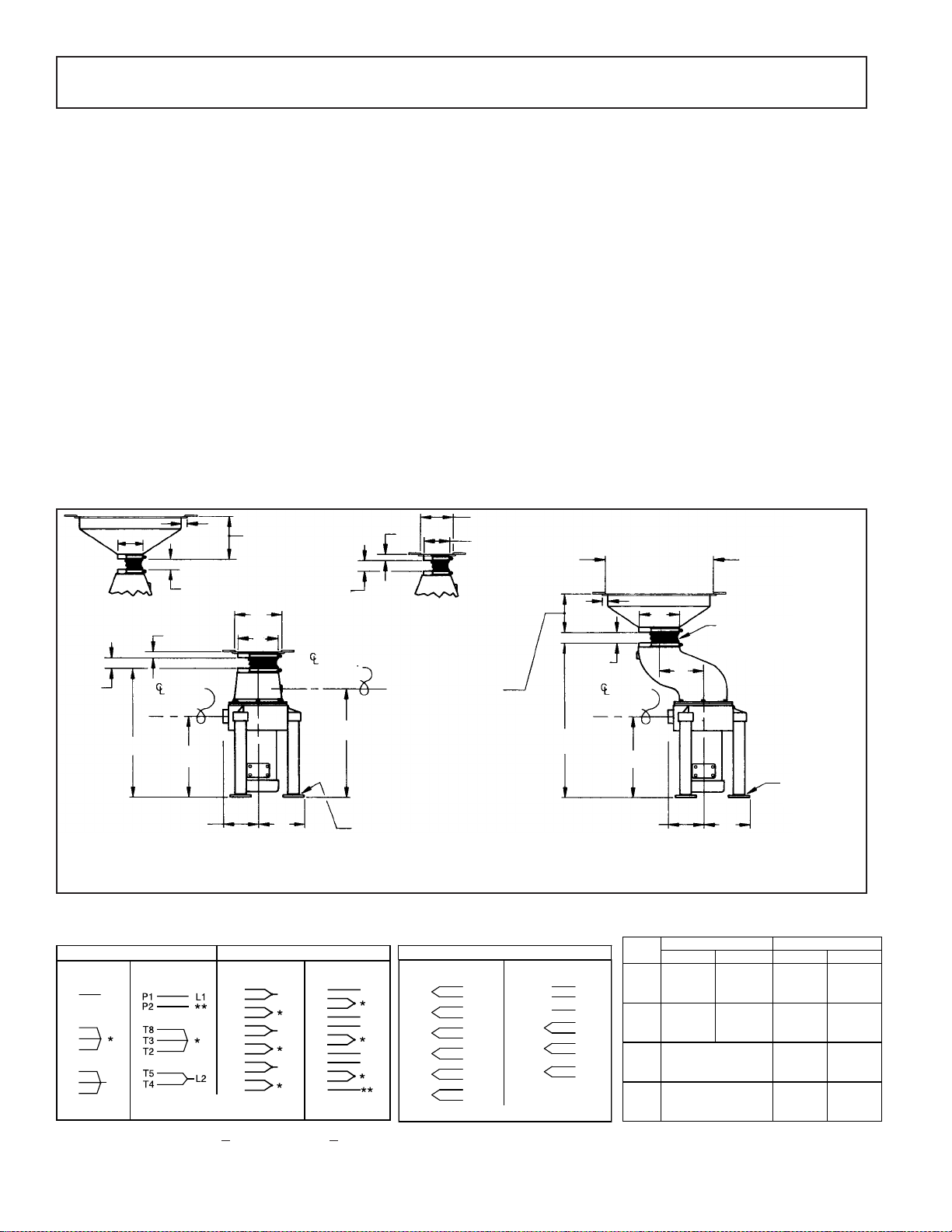
INSTALLATION DIAGRAM
1
1
⁄2”
4
1” MIN.
41⁄2” REGULAR DRUM WITH
6” MAX.
CONE MOUNTING ASSEMBLY
1”
1” MIN.
6” MAX.
DRAIN
1”
CUTOUT
6” FOR 12” CONE
5” FOR 15” CONE
7” FOR 18” CONE
1” MIN.
6” MAX.
8”
7”
WATER
1”
41⁄2” REGULAR DRUM WITH
SINK MOUNTING ASSEMBLY
INLET
6” FOR 12” CONE
5” FOR 15” CONE
7” FOR 18” CONE
CUTOUT 5
41⁄2
DIAMETER
” INSIDE
⁄2”
TABLE CUTOUT
13” FOR 12” CONE
16” FOR 15” CONE
19” FOR 18” CONE
1”
1” MIN.
6” MAX.
7”
8” LENGTH OF NEOPRENE
CONNECTOR SLEEVE FURNISHED.
MAY BE CUT TO DESIRED LENGTH.
8”
DRAIN
19”
23”
1
⁄2”
14
27”
141⁄2”
ADJUSTABLE
0” TO 2”
1
6
⁄4”
8”
ADJUSTABLE 0” TO 2 ”
DISPOSER SHOWN WITH REGULAR 7” DRUM
AND SINK MOUNTING ASSEMBLY
1
⁄4”
6
8”
DISPOSER SHOWN WITH OFFSET DRUM
AND CONE MOUNTING ASSEMBLY
NOTE: All dimensions shown at 0” foot height adjustment.
MOTOR WIRING DIAGRAMS
)RUXVHZLWK/HHVRQPRWRUV )RUXVHZLWK%DOGRUPRWRUV
SINGLE PHASE THREE PHASE
115 Volt, 60 Hz 230 Volts, 60 Hz 208/230 Volt, 60 Hz 460 Volt, 60 Hz
110 Volt, 50 Hz 220 Volts, 50 Hz 190-220 Volts, 50 Hz 380-440 Volts, 50 Hz
P1
L1
T8
P2
T3
T5
L2
T2
T4
Tied Together and Insulated
*
Insulated
**
T1
T7
T4
P4
T2
T8
T5
P5
T3
T9
T6
P6
T1
**
**
L1
L2
L3
L1
T7
T4
P4
T2
L2
T8
T5
P5
T3
L3
T9
T6
P6
6 = Six 9 = Nine
THREE PHASE WITH THERMAL
208-230 Volts, 60 Hz
190-220 Volts, 50 Hz
Tied Together and Insulated
*
1
L1
7
2
L2
8
9
L3
3
10
*
4
11
*
5
12
*
6
460 Volts, 60 Hz
380 Volts, 50 Hz
L1 1
L2 2
L3 3
4
7
*
5
8
*
6
*
9
**10 **11 **12
Insulated
**
VOLTAGE-AMPERAGE TABLE
HP Volts Amps* Volts Amps*
1 1/2
SINGLE PHASE THREE PHASE
115 17.2 208 4.9
230 8.6 230 4.4
115 18.4 208 6.9
2
230 9.2 230 6.2
3
N/A
5 N/A
*Ratings are for 60 Hz operation
460 2.2
460 3.1
208 9.7
230 8.8
460 4.4
208 14.8
230 13.4
460 6.7
Page 6 Red Goat Disposers 10/12
Page 7
“B” SERIES - Installation and Connection
THREE PHASE
208-230 Volts, 60 Hz 460 Volts, 60 Hz
190-220 Volts, 50 Hz 380 Volts, 50 Hz
Tied Together and Insulated
*
L1
L2
L3
1
7
2
8
3
9
4
5
6
4
7
1
5
8
2
6
9
3
L1
L2
L3
HP Volts Amps*
208 9.5
230 9.0
460 4.5
208 15.2
230 13.6
460 6.8
208 23
230 22
460 11
208 33
230 30
460 15
10
THREE PHASE
3
5
7 1/2
NOTE: PLUMBING AND ELECTRICAL CONNECTIONS SHALL BE MADE IN COMPLIANCE WITH APPLICABLE
LOCAL CONSTRUCTION CODES.
PLUMBING
Inlet: Cold water supply to disposer shall be 1⁄2" service line with a minimum of 20 lbs. flow pressure, piped as close to
disposer as possible. All disposer and control connections shall be 1⁄2" pipe size.
Sewer Outlet: 2" waste line should have trap with conveniently located clean out. Do not connect through a grease trap.
Avoid bends, elbows, tees, etc., to reduce the possibility of plumbing stoppage. A globe valve, used for metering flow,
must be installed between solenoid valve and cone or sink. Water swirl inlet valves should be located nearest operator.
See Typical Installation Diagram.
ELECTRICAL
Follow guidelines set forth by NEC standards. Disposer branch circuit shall be sized and fused (circuit breakers) as
required by motor. The disposer must be connected to a grounded, metal, permanent wiring system; or a disposergrounding conductor must be run with the circuit conductors and connected to the disposer-grounding terminal or lead
on disposer. All connections, junction boxes and conduits must be watertight (NEMA 4).
TESTING See Start-up and Run Section.
INSTALLATION DIAGRAM
TABLE CUTOUT
13” FOR 12” CONE
16” FOR 15” CONE
19” FOR 18” CONE
43⁄4” FOR 12” CONE
1
⁄2” FOR 15” CONE
5
1
⁄4” FOR 18” CONE
6
WATER
INLET
1
⁄2”
13
(141⁄2
”)
*
1” MIN.
6” MAX.
27”
(28)
7”
8”
DRAIN
1”
8” LENGTH OF NEOPRENE
CONNECTOR SLEEVE FURNISHED.
MAY BE CUT TO DESIRED LENGTH.
WATER
INLET
*
111⁄2”
(12
1
⁄2”)
*
131⁄2”
(14
1
⁄2
”)
*
1” MIN.
6” MAX.
221⁄2”
(23
⁄2”)
CUTOUT
8”
7”
*
1” MIN.
6” MAX.
1”
DRAIN
1
⁄2”)
*
111⁄2”
1
(12
Red Goat Disposers 10/12 Page 7
3
95⁄8”
⁄8”
7
DISPOSER SHOWN WITH REGULAR DRUM
AND SINK MOUNTING ASSEMBLY
ADJUSTABLE 0” TO 2 ”
3
7
DISPOSER SHOWN WITH OFFSET DRUM
AND CONE MOUNTING ASSEMBLY
5
9
⁄8”
⁄8”
ADJUSTABLE 0” TO 2 ”
NOTE: All dimensions shown at 0” foot height adjustment.
MOTOR WIRING DIAGRAM VOLTAGE-AMPERAGE TABLE
Page 8
“C” SERIES - Installation and Connection
THREE PHASE
208-230 Volts, 60 Hz 460 Volts, 60 Hz
190 Volts, 50 Hz 380 Volts, 50 Hz
Tied Together and Insulated
*
L1
L2
L3
1
7
2
8
3
9
4
5
6
4
7
1
5
8
2
6
9
3
L1
L2
L3
HP Volts Amps*
208 9.5
230 9.0
460 4.5
208 15.2
230 13.6
460 6.8
208 23
230 22
460 11
208 33
230 30
460 15
10
THREE PHASE
3
5
7 1/2
NOTE: PLUMBING AND ELECTRICAL CONNECTIONS SHALL BE MADE IN COMPLIANCE WITH APPLICABLE
LOCAL CONSTRUCTION CODES.
PLUMBING
Inlet: Cold water supply to disposer shall be 1⁄2" service line with a minimum of 20 lbs. flow pressure, piped as close to
disposer as possible. All disposer and control connections shall be 1⁄2" pipe size.
Sewer Outlet: 3" waste line should have trap with conveniently located clean out. Do not connect through a grease trap.
Avoid bends, elbows, tees, etc., to reduce the possibility of plumbing stoppage. A globe valve, used for metering flow,
must be installed between solenoid valve and cone or sink. Water swirl inlet valves should be located nearest operator.
See Typical Installation Diagram.
ELECTRICAL
Follow guidelines set forth by NEC standards. Disposer branch circuit shall be sized and fused (circuit breakers) as
required by motor. The disposer must be connected to a grounded, metal, permanent wiring system; or a disposergrounding conductor must be run with the circuit conductors and connected to the disposer-grounding terminal or lead
on disposer. All connections, junction boxes and conduits must be watertight (NEMA 4).
TESTING See Start-up and Run Section.
INSTALLATION DIAGRAM
TABLE CUTOUT
13” FOR 12” CONE
16” FOR 15” CONE
19” FOR 18” CONE
3
⁄4” FOR 12” CONE
4
1
⁄2” FOR 15” CONE
5
1
⁄4” FOR 18” CONE
6
WATER
INLET
1” MIN.
6” MAX.
DRAIN
7”
1”
8” LENGTH OF NEOPRENE
CONNECTOR SLEEVE FURNISHED.
MAY BE CUT TO DESIRED LENGTH.
1
10
⁄2”
WATER
INLET
1” MIN.
6” MAX.
1”
DRAIN
CUTOUT
8”
7”
221⁄2”
1
121⁄2”
⁄2
”)
(26
*
1
⁄4”
10
DISPOSER SHOWN WITH REGULAR DRUM
AND SINK MOUNTING ASSEMBLY
11”
1
⁄2”
13
ADJUSTABLE 0” TO 2 ”
27”
1
12
⁄2”
1
10
⁄4”
DISPOSER SHOWN WITH OFFSET DRUM
AND CONE MOUNTING ASSEMBLY
11”
1
13
⁄2”
ADJUSTABLE 0” TO 2 ”
NOTE: All dimensions shown at 0” foot height adjustment.
MOTOR WIRING DIAGRAM VOLTAGE-AMPERAGE TABLE
Page 8 Red Goat Disposers 10/12
Page 9

TYPICAL INSTALLATION
START-UP AND RUN CHECK
1. Check that vinyl silver trap scrapping ring is fully seated.
2. Check that all connections are secure.
3. Check that disposer is secured to floor.
4. Open terminal wiring box on motor; pull out and separate motor leads to permit ampere reading on each leg.
Leave all connections and insulation in place.
5. Clamp ammeter over input feed lead.
6. Turn on disposer.
8. Check for leaks, water flow, excessive noise or vibration, and regulate water flow if required.
7. Take ampere readings on each leg and verify against factory-checked motor test results.
NOTE: Before checking rotation reversal, be sure disposer is empty. Wear safety glasses or goggles. BE SURE POWER
SWITCH IS OFF SHOULD ADJUSTMENTS ON DISPOSER BE NECESSARY. NEVER REACH INTO DISPOSER WHEN DIS-
POSER IS RUNNING.
9. If disposer is connected to a reversing control, whether automatic or manual, check reversing.
10. If disposer is connected to a manual reversing drum switch or contactor, START motor in forward position and note rotation
through top opening as motor coasts to a stop. RESTART motor in reverse position. Verify that disposer restarted in opposite
direction.
11. If disposer is connected to a control center with automatic reversing (Model RAC1/ RAC2), verify if disposer reverses.
NOTE: Motor must be stopped or 30 seconds must have elapsed before pushing START; otherwise, motor will not reverse. This
is a safety cycle feature. Should START button be pressed prior to elapsed time, motor will run in same direction. Direction Test:
A.) Press Start- Disposer Run. B.) Press Stop (note coast down direction. C.) Wait 30 sec. after motor stops. D.) Press startDisposer should run is opposite direction.
12. If disposer is wired with a (RAC1/ RAC2), There are 3 trim-pots on the Control Module inside the controller that adjust operation. (To enable or disable clean out cycles) For more information about this Eco-Mizer: Electricity and Water Saver please
see the Instructions For Adjustable Timer With Auto Shut Down spec sheet in the control box. This timer is used to control the
shut down sequence of industrial garbage disposal units. When either the Stop input is activated or the Auto Shut Down timer
times out, the two stage shut down sequence begins. The first stage is Clean Out, where both the motor and water flow continue
for up to 2 minutes. The second stage is Positive Flush, where the motor is stopped, but the water flow is continued, also for up
to 2 minutes. The disposal may be restarted at any time, but if the motor has been off for more than 30 seconds, its direction will
be reversed.
13. In all shutdown phases, be sure water is being shut off by the closing of the solenoid valve.
14. Reinsert all wiring, close all covers and shut all doors that were open during run check.
Red Goat Disposers 10/12 Page 9
Page 10

OPERATION
1. Check that disposer is empty and clean from previous use.
2. Check that vinyl silver trap scrapping ring is in place and properly seated over throat opening in cone or sink.
3. Turn disposer ON. Note that water is flowing into top cone or into sink via the water swirl fitting.
WARNING: Never feed waste by hand past vinyl silver trap ring or reach inside running disposer .
NOTE: Do not feed metal, wood, cloth, rubber, corn husks, plastics, plastic sheets of bags, styrofoam, or other foreign
matter. A periodic clean out of such material from the disposer is advisable.
4. Proceed with dish cleanup, feeding waste gradually. DO NOT pack waste into disposer waste chamber .
5. After each use, if disposer is wired with manual controls, allow disposer to run (motor and water) for at least 2
minutes. This clean-out cycle will empty the disposer and flush the waste line, preventing potential drain
stoppage.
6. Should motor stop during use cycle, SHUT OFF POWER IMMEDIA TELY, via ON-OFF switch. If disposer is
connected to Model RAC2 Control Center , shut OFF power at black emergency disconnect handle; on manual
switches, turn branch circuit disconnect to OFF.
A. Remove vinyl silver saver scrapping ring and check waste chamber through top opening and remove foreign
objects that may have caused stoppage.
B. Check to see if rotor turns freely.
C. If rotor turns freely, replace vinyl silver saver scrapping ring and turn disposer ON.
If disposer fails to start and run, an obstruction may still be binding the rotor .
A. Turn disposer OFF. Using a wooden bar or wooden handle, pry and push against the impact bars on the
rotor to break it free; then remove object.
B. Turn disposer ON and if motor fails to start, the thermal protector, either in the motor (“H” and “A” Series) or
in the controls, may have tripped.
C. Push reset button on thermal protector.
If disposer still fails to start, check for blown fuses or tripped circuit breakers in the branch circuit (especially on
three-phase installations) to be sure that all power legs are feeding motor .
TROUBLESHOOTING
DISPOSER DOES NOT START WHEN NEW
Manual reset button of thermal protector is tripped. On “H” and “A” Series, reset button is on motor; on “B” and “C”
Series, reset button is in control box.
Fuses or circuit breaker on branch circuit feed line have tripped.
Electrical connectionf on motor, in panel or feed lines not tight.
Headers have not been installed in starter, if starter is used in circuit.
DISPOSER DOES NOT START AFTER STANDING UNUSED FOR A PERIOD OF TIME
Clean out cycle too short. When disposer is stopped too early, the remaining water slowly drains out carrying the
shattered waste particles into the very close clearance opening between sizing ring and rotor, where it hardens and
solidifies, acting as a binding agent between the two parts. The motor at start-up is unable to overcome the dried
blockage (usually on low horsepower disposers).
DISPOSER STALLS WHEN IN OPERATION
Large quantities of foreign material (rags, wood pieces, rubber bands, strings, pieces from floor mops, cellophane
and polyethylene) which will not disintegrate, cause the motor to overheat and the thermal protector to trip.
Not enough water volume flow (GPM) causing thermal protector to trip.
Thermal protectors (heaters) sized too small, causing nuisance tripping.
Page 10 Red Goat Disposers 10/12
Page 11

TROUBLESHOOTING
(continued)
DISPOSER OPERATES BUT DISINTEGRATION AND DISCHARGE IS SLOW
Not enough water volume flow (GPM).
Worn shattering mechanism (impact bars, sizing ring, rotor).
Large amounts of foreign material in waste chamber.
DISPOSER MOVES WHEN STARTED
Large amounts of unshattered waste in chamber.
Rotor unbalanced due to loose impact bar.
Disposer not anchored to floor.
DRAIN LINE CLOGS
Worn shattering mechanism (impact bars, sizing ring, rotor) permitting large waste particles to flow through.
Large amount of paper and non-food particles being fed into disposer .
Not enough water volume flow (GPM).
DISPOSER DOES NOT TURN OFF (AFTER CLEAN OUT CYCLE, IF WIRED WITH RAC2)
Stop button in switch or control defective.
Timer in Model RAC2 control center defective.
DISPOSER DOES NOT REVERSE
Contacts in manual reversing switch burned.
Contactor in auto reversing control center defective.
Reversing circuit in auto reversing control center defective.
Time lapse safety circuit in auto reversing control center defective.
Motor not wired as indicated in wiring diagram.
SEVERE VIBRATION DURING OPERATION
Loose or broken impact bars.
Unshattered waste lodged in rotor.
Severe rotor damage from metal objects being fed into disposer .
MOTOR RUNS BUT NO WATER FLOW
Solenoid valve improperly wired.
Defective solenoid valve coil.
No water flow in main feed line.
MOTOR NUT TURNING AT PROPER RPM
Low voltage on incoming feed line.
On three-phase hookups, no voltage on one feeder line (leg).
Motor not wired as indicated in wiring diagram (low to high, high to low voltsO.
LOUD NOISE FROM MOTOR AREA
Upper or lower or both bearings worn.
Leakage of disposer seals.
SMOKE OR BURNING ODOR FROM MOT OR
Incoming voltage not correct.
On three-phase hookups, no voltage on one feeder line (leg).
Water leaking into motor through faulty seals.
Disposer being overloaded, especially with foreign material.
Improper motor connections.
Page 12

TROUBLESHOOTING
MOTOR BURNS OUT
Internal winding short.
Water leaking into motor through faulty seals.
Disposer being overloaded.
Incoming voltage not correct.
Thermal protectors (heaters) not tripping, sized too large.
WATER LEAKING FROM BASE OR DISPOSER
Defective seals.
Hole worn in base.
Motor mounting screws not sealed on “H” and “A” Series units.
Leaking plumbing connections or leaking sink mounts.
WATER SPLASHING UP FROM DISPOSER
Building water pressure too high.
Globe valve not installed or needs adjustment.
WATER FLOWS BUT MOTOR DOES NOT RUN
Thermal protectors (heaters) not installed in starter.
Motor not wired as indicated on wiring diagram.
Control not wired correctly.
(continued)
MAINTENANCE
Waste disposer troubles usually involve plumbing. A preventative maintenance program is advisable to keep waste line
stoppage and disposer repair at a mininum. Any sewer problem occurring shortly after your disposer has begun
operation cannot be caused by the new machine. It will be the result of connecting to either an inadequate waste line,
or to one that has not been properly cleared before use. On the other hand, if waste line clogging occurs after the
disposer has been running trouble-free for a year or more, this indicates probable need for servicing.
The slurry leaving a new disposer contains no discernible solids, so there is nothing to clog the waste line. In regular
use, however, wearing of the working parts is to be expected. As the gradual wear occurs, the solid particles passing
through the wider gaps in the shatter mechanism will grow increasingly larger, until waste line stoppage may result.
See Figures.
MONTHLY WEAR CHECK
NOTE: The following should be performed every two weeks if waste is of a highly abrasive consistency .
1. Shut OFF branch circuit power, or emergency disconnect on control panel when disposer has completed its
clean out cycle.
2. Loosen stainless steel clamps on neoprene connector sleeve.
3. Twist neoprene sleeve loose and remove.
4. On “B” and “C” Series, loosen Quick-Release body clamps and lift of f aluminum lid.
5. Remove any foreign objects (rubber bands, metal, wood, plastics, etc.) from waste chamber .
6. Check free movement of rotor.
7. The two points of probable wear are the leading edges of the impact bars and the spacing between the outer
edges of the rotor and the inner diameter of the sizing ring teeth (Figure 1, Page 13). When one end of each
impact bar is worn rounded, as shown in Figure 2, Page 13, they need to be reversed (if disposer is wired to an
automatic reversing control).
A. Loosen four hex socket head cap Allen screws to release the bars. Should it be necessary, use liquid wrench
or a mixture of oil and kerosene to help loosen the screws.
Page 12
Red Goat Disposers 10/12
Page 13

MAINTENANCE
B. Reverse bars and reinstall Allen screws.
C.
When the edges of the reversed impact bars become rounded (Figure 3), the bars must be replaced.
See below and Page 14.
8. The second point of wear is the clearance between the outer edge of the rotor and the inner diameter of the
sizing ring teeth (Figure 3).
If the space between the rotor and sizing ring has grown to 3⁄32”, (.094) and the impact bars are worn (rounded)
as shown in Figure 3, replacement of total rotor and sizing ring is advisable. See below and Page 14.
NOTE: If 3⁄32” space between rotor sna sizing ring is left to continue to increase, waste line stoppage may result as
increasingly large whole sections of waste will pass through sizing ring without breaking up.
(continued)
FIG. 1
These bars are badly worn and need reversing. FIG. 2
Remove Allen screws and reverse bars.
When the rotor and sizing ring are new,
this spacing is 0.0 12” (less then
POINTS OF WEAR
When these impact bars are reversed,
presenting new working sides, this
disposer will function well even though
this space may have grown to 3⁄32”.
At this stage of wear, no new parts
are needed.
With uniform wear on the rotor and the
teeth, spacing between has increased,
but the new faces of the reversed bars
restore efficiency.
1
⁄
64”).
These bars have had their double life. FIG. 3
With both sides well worn, it is evident that this disposer was
properly cared for, getting maximum length of service from all parts.
Red Goat Disposers 10/12
At this stage of double wear on bars,
this space may be 3⁄32” (.094). Check
with feeler gauge or U.S. Std. #13 gauge
wire.
At this stage, bars only may be
renewed–provided spacing between
rotor and teeth has not grown to 3⁄32”
and if waste line appears capable of
handling the slurry output.
Page 13
Page 14

PARTS REPLACEMENT
WARNING: ALWAYS SHUT OFF MAIN POWER DISCONNECT BEFORE PERFORMING
MAINTENANCE OR PARTS REPLACEMENT.
IMPACT BARS (Series A, B and C)
1. Shut off main power disconnect.
2. Disconnect water line feeding into waste chamber, if applicable.
3. Loosen stainless steel clamps and remove neoprene sleeve.
4. On Series “A” disposers, remove 41⁄2” or 7 ” waste chamber by loosening and removing the six hex head bolts
holding chamber to base.
On Series “B” and “C” disposers, remove aluminum lid by loosening quick-release head clamps.
5. Insert wedge at impact bar between rotor and sizing ring to prevent rotor rotation.
6. Loosen hex socket head cap Allen screws and remove impact bars. Use liquid wrench or a solution of oil and
kerosene if necessary.
7. Install new impact bars in milled slots, after cleaning slots of foreign materials. Be sure new bars fit tightly into
slots and sit flatly, making metal to metal contact.
8. Remove anti-rotation wedge.
9. Replace removed components and reconnect disposer to sink or dishtable.
ROTOR AND/OR SIZING RING
1. Shut off main power disconnect.
2. Disconnect water line feeding into waste chamber, if applicable.
3. Loosen and disconnect disposer from sink or dishtable.
4. Remove waste chamber by loosening and removing the hex head bolts holding chamber to base.
5. Remove center cover bolt and plate.
6. Remove the two centering hold down studs from sizing ring and lift off sizing ring.
7. Remove old gaskets from base sizing ring or waste chamber .
8. Lift off rotor. On “B” and “C” Series, provisions for use of a wheel puller are cast into rotor. When using wheel
puller, thead back cover bolt onto motor shaft 1⁄2”. This will protect the threaded motor shaft.
9. Remove key from shaft.
10. Clean and inspect keyway.
11. Inspect motor seal system. If replacement is necessary , do so now. See Instructions on Page 13.
12. Oil motor shaft and slide on new rotor . Be sure rotor has seated fully on motor shaft shoulder and that shaft is
below machined surface on rotor.
13. Reinsert key. Series “B” and “C” use two keys. BE SURE the keys make metal to metal contact on all surfaces
in the rotor and motor shaft keyways and that the key is the full length of the keyway. Short keys will shear at
peak loads. Rotate rotor slightly to be sure there is no radial play between the rotor and motor shaft.
14. Insert cover gasket, plate and bolt to lock down rotor .
15. Torque cover bolt to 34 ft-lbs.
16. Install one new gasket on base.
17. Place sizing ring over gasket on base and thread in new centering studs.
18. Center sizing ring on rotor, turning rotor several complete turns. There should now be approximately 1⁄64” running
clearance between rotor and sizing ring.
19. Lock sizing ring into place with the centering studs. BE SURE sizing ring did not move and that running
clearance has been maintained.
20. Place the second gasket over centering studs and install waste chamber .
21. Lock waste chamber into place and reconnect parts removed earlier .
Page 14 Red Goat Disposers 10/12
Page 15

PARTS REPLACEMENT
(continued)
MOTOR SEALS AND/OR MOTOR
1. Shut off main power disconnect.
2. Disconnect disposer from dishtable and waste line; remove floor mount and disconnect electric line feeding
motor.
3. Slide out disposer.
4. Remove rotor and sizing ring, as described on Page 14.
5. Series “H” and “A”: Remove four (4) motor bolts.
Series “H” and “A”: Turn disposer over resting base, especially sizing ring clamping surface, on wooden blocks.
6. Series “B” and “C”: Remove four (4) motor bolts and lift of f motor.
Series “B” and “C”: Drive out the lip seal and cartridge seal; clean seal seating area.
Series “B” and “C”: Turn base over and set in the new lip seal (open side of seal facing up) and oil with SAE 30
oil.
7. Install cartridge seal.
A. Place light application of Permatex adhesive gasket sealant or equivalent in seal bore in base.
B. Fully immerse new cartridge seal in SAE 30 oil.
C Install new cartridge seal (rubber seal ring up), using installation tool (available separately) making sure seal
is fully seated in bore.
8. Turn base back onto the wooden blocks.
9. Clean motor shaft and oil shaft well with SEA 30 oil.
10. Slide motor back over seals and fasten motor. BE SURE motor is in same position as before for electrical
connections.
11. Turn base with motor back over and make sure rubber seal ring on cartridge seal is in place.
12. Re-install components, as listed on Page 14 and reconnect disposer .
TEST RESULTS
Red Goat Disposers 10/12
Page 15
Page 16

“H” SERIES REPLACEMENT PARTS LIST
KEY NO. PART NO. NAME: DESCRITION/ QTY PER MACH. KEY NO. PART NO. NAME: DESCRITION/ QTY PER MACH.
1 30-H-RSA RSA Head Assy1 1 28 30-A-436 Motor: 1.5 HP, 3PH 1
(Includes 2-9) (Includes 19-21 & 28)
2 06-H-8 Sink Stopper: "H" Series RSA 1 29 02-A-462 Thermal Protector: #MWJ57KB 1
3 27-H-15 Sink Mount: Threaded 1 28 30-A-480 Motor: 2 HP, 1PH 1
4 07-H-19 Gasket: RSA Rubber 1 (Includes 19-21 & 28)
5 07-H-20 Gasket: RSA Fiber 1 29 02-5-486 Thermal Protector: #BE J44DB 1
6 08-H-21 Screw, Hxhd 5/16-18 x 3/4 6 28 30-A-442 Motor: 2 HP, 3PH 1
7 08-HA-311 Washer: Lock Split 5/16 13 (Includes 19-21 & 28) 1
8 51-H-17 RSA Head 1 29 02-A-465 Thermal Protector:#CWJ58KB LEESON 1
9 07-H-18 Gasket: Splash Guard 1 31 06-5-505 Rubber Boot: Thermal Protector 1
10 06-HA-ST4
Silver Saver: 4 1/2"
1 33 08-HA-282 Key: Woodruff #606 1
11 07-H-34 Gasket: "H" Series cone 1 34 02-HA-521 V-Ring Seal LEESON 1
12 08-HA-22 Screw: Hxhd 5/16-18 x 1, SS 4 35 02-HA-522 Seal: Motor Shaft LEESON 1
13 51-H-12LD Drum 1 36 02-5-400 Bearing: #205 1
14 08-HA-17 Nut: Hex 5/16-18 2 41 02-HA-399 Bearing: #203 1
15 10-5-27. Pipe Plug: 1⁄2” 1 42 40-H-016 Center Support Leg Kit (H Model) 1
16 07-H-10 Gasket: Sizing Ring 2 (Includes 42-48)
17 08-HA-16 Centering Stud 2
18 30-H-9D Sizing Ring 1 40-H-504 H-Complete Renewal Kit 1
19 08-6-276 Nut: Hex Jam Nyloc, 5/8 x 18, SS 1 S/N 060185H01/ RG-1000 Forward
20 08-6-277 Washer: Flat H D5/8 x .134 thick 1 40-H-1DA H-Rotor Kit (Includes 19-22) 1
21 07-6-98. Gasket: Turntable Mounting 1 40-H-9DA H-Sizing Ring Kit 1
22 30-H-1D Rotor: With Cast-On Impact Bars 1 (Includes 7, 14 & 16-18)
23 07-HA-83 Cartridge Seal 1 40-HA-507 H-Motor Seal Kit (Includes 23 & 27) 1
04-HA-263 Install. Tool: HA Cartridge Seal 1 S/N 060185H01/ RG-1000 Forward
24 08-5-24. Screw: Skhd 3/8-16x3/4 Nyloc SS 4
25 30-H-1140 Base Assy: Includes Seals Installed 1 FOR USE WITH BALDOR MOTORS ONLY
26 06-5-849 Drain Coupling: “H” Series 1 19 08-H-21 Screw: Hxhd 5/16-18 x 3/4 SS Nyloc 1
27 07-HA-5 Gasket: Motor/Base 1 20 09-HA-2 Coverplate 1
28 30-H-431 Motor: 3/4 HP, 1PH 1 21 07-HA-3 Gasket: Coverplate 1
(Includes 19-21 & 28) 33 02-HA-100 Key 1
28 30-H-432 Motor: 3/4 HP, 3PH 1 29 02-A-475 Thermal Protector: #MYJ42WB 2HP 1
(Includes 19-21 & 28) 1
28 30-H-523 Motor: 1 HP, 1PH 1 (NON-STOCK ITEMS)
(Includes 19-21 & 28) 1 30, 32 & 37-40 PLEASE CONTACT OUR FACTORY
29 02-MC-6068 Thermal Protector: #CE J53CB 1
28 30-H-524 Motor: 1 HP, 3PH 1
(Includes 19-21 & 28)
28 30-H-435 Motor: 1.5 HP, 1PH 1
(Includes 19-21 & 28) 1
29 02-HA-459 Thermal Protector: #CE J50CA 1
Page 16 Red Goat Disposers 10/12
Page 17

“H” SERIES REPLACEMENT PARTS DIAGRAM
Red Goat Disposers 10/12 Page 17
Page 18

“A” SERIES REPLACEMENT PARTS LIST
KEY NO.
PART NO.
NAME: DESCRITION/ QTY PER MACH.
KEY NO. PART NO. NAME: DESCRITION/ QTY PER MACH.
1 06-HA-ST4 Silver Saver: 4 1⁄2” 1 26 02-5-400 Bearing: #205 LEESON 1.5 & 2HP UP 1
06-ABC-ST7 Silver Saver: 7” 1 27 02-HA-399 Bearing: #203 LEESON 1.5 & 2HP LOW 1
2 06-A-818 Connector Sleeve: 4 1⁄2” dia. x 8” 1 23 30-AB-448 Motor: 3 HP/3 PH Includes 14-16 &23 1
06-A-414 Connector Sleeve: 4 1⁄2” dia. x 4” 1 24 02-A-464 Thermal Protector: #BYJ36KF LEESON 1
06-ABC-834 Connector Sleeve: 7” dia. x 8” 1 26 02-BC-401 Bearing: #206 LEESON 1
06-ABC-434 Connector Sleeve: 7” dia. x 4” 1 27 08-SM-1418 Bearing: #204 LEESON 1
3 08-A-19 Clamp: Connector Sleeve 4 1⁄2” 2 23 30-A-481B Motor: 5 HP/3 PH Includes 14-16 &23 1
08-ABC-33 Clamp: Connector Sleeve 7” 2 24 02-A-488 Thermal Protector: #BYJ32KF LEESON 1
4 51-A-11AS Drum: 4 1⁄2” Throat 1 26 02-BC-401 Bearing: #206 LEESON 1
51-A-11S Drum: 7” Throat 1 27 08-SM-1418 Bearing: #204 LEESON 1
51-A-81 Offset Drum: 7” Throat 1 29 02-A-523 Seal: V-Ring 3 & 5 HP LEESON 1
5 08-HA-22 Screw: Hxhd 5/16-18 x 1, SS 4 30 02-A-524 Seal: Motor Shaft 3 & 5 HP LEESON 1
6 08-HA-311 Washer: Lock Split 5/16 6 28 08-HA-282 Key: Woodruff #606 LEESON 1
7 08-HA-17 Nut: Hex 5/16-18 2 29 02-HA-521 V-Ring Seal LEESON 1
8 10-5-27. Pipe Plug: 1⁄2” 1 30 02-HA-522 Seal: Motor Shaft 1.5 & 2 HP LEESON 1
9 07-A-10 Gasket: Sizing Ring 2 32 06-5-505 Rubber boot: Thermal Protector 1
10 08-HA-16 Centering Stud 2 34 09-A-928 Leg Assy w/Foot: 2" X 13.5, SS 3
11 30-A-9 Sizing Ring 1
12 08-5-24. Screw: Skhd 3/8-16 x3/4 Nyloc SS 2 40-A-503 A-Complete Renewal Kit 1
13 30-A-27 Impact Bar 2 S/N 060185A01/ RG-1000 Forward
14 08-6-276 Nut: Hex Jam Nyloc, 5/8-18, SS 1 40-A-1A A-Rotor Kit (Includes 12-17) 1
15 08-6-277 Washer: Flat, HD, 5/8 x.134 thick 1 40-A-9A A-Sizing Ring Kit 1
16 07-6-98. Gasket: Turntable Mounting 1 (Includes 6, 7 & 9-11)
17 51-A-1 Rotor 1 40-HA-507 A-Motor Seal Kit (Includes 19 & 22) 1
30-A-1 Rotor Assy: w/Impact Bars 1 S/N 060185A01/ RG-1000 Forward
(Includes 12, 13 & 17)
18 08-5-24. Screw: Skhd 3/8-16 x 3/4 Nyloc SS 4 FOR USE WITH BALDOR MOTORS ONLY
19 07-HA-83 Cartridge Seal 1 14 08-H-21 Screw: Hxhd 5/16-18 x 3/4 SS Nyloc 1
04-HA-263 Install. Tool: HA Cartridge Seal 1 15 09-HA-2 Coverplate 1
20 30-A-1141 Base Assy: Includes Seals Installed 1 16 07-HA-3 Gasket: Coverplate 1
21 06-5-851 Drain Coupling: “A” & “B” Series 1 28 02-HA-100 Key 1
22 07-HA-5 Gasket: Motor/Base 1 24 02-A-475 Thermal Protector: #MYJ42WB 2HP 1
MOTOR OPTIONS 24 CYJ52AB Thermal Protector: #CYJ52AB 3HP 1
23 30-H-435 Motor: 1.5 HP/1PH Includes 14-16 &23 1 24 BY J23WB Thermal Protector: #BY J23WB 5HP 1
24 02-HA-459 Thermal Protector: #CE J50CA 1 26 02-5-400 Bearing: #205 UPPER 2HP 1
23 30-A-436 Motor: 1.5 HP/3PH Includes 14-16 &23 1 27 02-HA-399 Bearing: #203 LOWER 2HP 1
24 02-A-462 Thermal Protector: #MWJ57KB 1 26 02-BC-401 Bearing: #206 UPPER 3 & 5HP 1
23 30-A-480 Motor: 2 HP/1PH Includes 14-16 &23 1 27 02-5-400 Bearing: #205 LOWER 3 & 5HP 1
24 02-5-486 Thermal Protector: #BE J44DB 1
23 30-A-442 Motor: 2 HP/3PH Includes 14-16 &23 1 (NON-STOCK ITEMS)
24 02-A-465 Thermal Protector:#CWJ58KB LEESON 1 25, 31, 33, & 35-38 PLEASE CONTACT OUR FACTORY
Page 18 Red Goat Disposers 10/12
Page 19

“A” SERIES REPLACEMENT PARTS DIAGRAM
Red Goat Disposers 10/12 Page 19
Page 20

“B” SERIES REPLACEMENT PARTS LIST
KEY NO. PART NO. NAME: DESCRITION/ QTY PER MACH. KEY NO. PART NO. NAME: DESCRITION/ QTY PER MACH.
1 06-ABC-ST7 Silver Saver: 7” 1 27 30-BC-151 Motor: 5 HP, 3PH Baldor 1
2 06-ABC-834 Connector Sleeve: 7” dia. x 8” 1 (Includes 19-21 & 28)
06-ABC-434 Connector Sleeve: 7” dia. x 4” 1
3 08-ABC-33 Clamp: Connector Sleeve 7” 2 27 30-BC-161 Motor: 7.5 HP, 3PH Baldor 1
4 01-B-36L Lid: 7” Aluminum 1 (Includes 19-21 & 28)
5 07-B-39 Gasket: Lid 1
6 51-B-36 Drum 1 27 30-BC-171 Motor: 10 HP, 3PH Baldor 1
51-B-80 Offset Drum 1 (Includes 19-21 & 28)
30-B-36 Drum Assy (includes 6 & 10-12 1
7 08-BC-71 Screw: Hxhd 3/8-16 x 1-1/2 6 29 08-5-24. Screw: Skhd 3/8-16 X 3/4, Nyloc SS 4
8 08-BC-312 Washer: Lock Split 5/16 13 30 08-BC-283 Key, Woodruff: #808 1
9 08-BC-1029 Nut: Hex 3/8-16 6 31 07-BC-903 Lip Seal: 1 7⁄8” OD Baldor 3-10 HP 1
10 08-BC-67 Thumb Screw: Lid Clamp 4 32 02-BC-403 Bearing: #306 1
11 51-BC-65 Lid Clamp 4 35 02-BC-401 Bearing: #206 1
12 08-BC-285 Screw: Hxhd 3/8-15 x 1-1/2 4 36 09-BC-927 Leg Assy w/Foot: 2” x 9.6, SS 3
13 07-B-32 Gasket: Sizing Ring 2
14 08-BC-1028 Centering Stud 2 40-B-501 B-Complete Renewal Kit 1
15 30-B-31 Sizing Ring 1 (S/N 060185B01/ RG-1000 Forward)
16 10-5-27. Pipe Plug: 1/2 1 40-B-1A B-Rotor Kit (Includes 17-22) 1
17 08-5-24. Screw: Skhd 3/8-16 X 3/4, Nyloc SS 4 40-B-31A B-Sizing Ring Kit 1
18 30-B-6 Impact Bar 2 (Includes 8-9 & 13-15)
19 08-6-280 Nut: Hex Jam Nyloc, 7/8-14, SS 1 40-B-502 B-Motor Seal Kit (Includes 23-24) 1
20 08-6-281 Washer: Flat, HD, 7/8 x .134 thick 1 (S/N 060185B01/ RG-1000 Forward)
21 07-BC-99 Gasket: Turntable Mounting 1
22 51-B-1 Rotor 1 (NON-STOCK ITEMS)
30-B-1 Rotor Assy: w/Impact Bars 1 28, 33, 34, & 37 PLEASE CONTACT OUR FACTORY
(Includes 17, 18 & 22)
23 07-BC-84 Cartridge Seal 1
04-BC-264 Install. Tool: BC Cartridge Seal 1
24 07-B-14 Lip Seal 1
25 30-B-1142 Base Assy: Includes Seals Installed 1
26 06-5-851 Drain Coupling: “A” & “B” Series 1
27 30-B-141 Motor: 3 HP, 3PH Baldor 1
(Includes 19-21 & 28)
Page 20 Red Goat Disposers 10/12
Page 21

“B” SERIES REPLACEMENT PARTS DIAGRAM
Red Goat Disposers 10/12 Page 21
Page 22

“C” SERIES REPLACEMENT PARTS LIST
KEY NO. PART NO. NAME: DESCRITION/ QTY PER MACH. KEY NO. PART NO.
NAME: DESCRITION/ QTY PER MACH.
1 06-ABC-ST7 Silver Saver: 7” 1 26 30-BC-161 Motor: 7.5 HP, 3PH 1
2 06-ABC-834 Connector Sleeve: 7” dia. x 8” 1 (Includes 17-19 & 33)
06-ABC-434 Connector Sleeve: 7” dia. x 4” 1
3 08-ABC-33 Clamp: Connector Sleeve 7” 2 26 30-BC-171 Motor: 10 HP, 3PH 1
4 01-C-1136 Lid: 7" Offset Opening 1 (Includes 17-19 & 33)
4A 07-C-1039 Gasket: Lid 1
5 51-C-1036 Drum 1 27 08-BC-283 Key, Woodruff: #808 1
51-C-1080 High Drum 1 28 07-BC-903 Lip Seal: 1 7⁄8” OD Baldor 3-10 HP 1
51-C-80 Offset Drum 1 29 02-BC-403 Bearing: #306 1
30-C-1036 Drum Assy (Includes 9-11) 1 32 02-BC-401 Bearing: #206 1
6 08-BC-71 Screw: Hxhd 3/8-16 x 1-1/2 6 34 08-5-24. Screw: Skhd 3/8-16 X 3/4, Nyloc SS 4
7 08-BC-312 Washer: Lock Split 3⁄8” 8 35 09-BC-927 Leg Assy w/Foot: 2” x 9.6, SS 3
8 08-BC-1029 Nut: Hex 3/8-16 2
9 08-BC-67 Thumb Screw: Lid Clamp 4 40-C-505 C-Complete Renewal Kit 1
10 51-BC-65 Lid Clamp 4 (S/N 060185C01/ RG-1000 forward)
11 08-BC-285 Screw: Hxhd 1/4-20 x 1-3/4, SS 4 40-C-500 C-Complete Renewal Kit 1
11A 08-BC-286 Nut: Hex Nyloc, 1/4-20, SS 4 (Thru S/N 053185C17)
12 07-C-1032 Gasket: Sizing Ring 2 40-C-1001A C-Rotor Kit (includes 15-20) 1
13 08-BC-1028 Centering Stud 2 40-C-1031A C-Sizing Ring Kit 1
14 30-C-1031 Sizing Ring Assy 1 (Includes 7-8 & 12-14)
15 08-5-24. Screw: Skhd 3/8-16 X 3/4, Nyloc SS 4 40-C-1012A C-Motor Seal Kit 1
16 30-C-1006 Impact Bar 2 40-B-502 B-Motor Seal Kit 1
17 08-6-280 Nut: Hex Jam Nyloc, 7/8-14, SS 1 (S/N 010191/ RG-1000 forward)
18 08-6-281 Washer: Flat, HD, 7/8 x .134 thick 1
19 07-BC-99 Gasket: Turntable Mounting 1 (NON-STOCK ITEMS)
20 51-C-1001 Rotor 1 30, 31, 33, & 36 PLEASE CONTACT OUR FACTORY
30-C-1001 Rotor Assy: w/Impact Bars 1
(includes 15, 16 & 20)
21 07-BC-84 Cartridge Seal 1
04-BC-264 Install. Tool: BC Cartridge Seal 1
22 07-B-14 Lip Seal S/N 010191/ RG-1000 forward 1
23 30-C-1143 Base Assy: Includes Seals Installed 1
24 10-5-27. Pipe Plug: 1⁄2” 1
25 06-5-851 Drain Coupling: “C” Series 1
26 30-BC-151 Motor: 5 HP, 3PH 1
(Includes 17-19 & 33)
Page 22 Red Goat Disposers 10/12
Page 23

“C” SERIES REPLACEMENT PARTS DIAGRAM
Red Goat Disposers 10/12 Page 23
Page 24

RAC1 REPLACEMENT PARTS LIST
KEY PART NO. NAME: DESCRIPTION KEY PART NO. NAME: DESCRIPTION
1
03-5-988
2
03-5-987
3
03-5-1023
4
03-5-1025
5
03-5-1042
6
03-5-1034
7
08-6-258
8
03-5-1000
9
03-HAB-940
10
03-HAB-995
03-HAB-911
03-HAB-912
11
08-6-250
12
03-HAB-906
03-BC-907
03-C-909
SPECIFY HP, VOLTAGE, PHASE, MODEL AND SERIAL NUMBER WHEN ORDERING CONTACTORS AND OVERLOAD RELAYS.
Pushbutton Assy: Red (N.C.)
Pushbutton Assy: Black (N.O.)
Legend Plate: “STOP”
Legend Plate: “RUN”
Enclosure: Non-Metallic, RAC1 & 2
Control Module
Screw: Php HD, 8-32 x 1
Wiring Harness: RAC1
Fuse: 2.5 Amp
Transformer: 24V/115, 230V 50VA
Transformer: 24V/208, 230, 460V 50VA
Transformer: 24V/380V 50VA
Screw: Php HD, 8-32 x 1/2
Contactor: Rev, 10A, 24V, 50/60HZ
(Use w/ 0H, 1.5L, 1.5H, 2L, 2H & 5H)
Contactor: Rev, 17.5A, 24V, 50/60HZ
(Use w/ 0L, 1H, 2.5H, 5L, 7H & 10H)
Contactor: Rev, 32A, 24V, 50/60HZ
(Use w/ 1L, 2.5L, 7L & 10L)
13
14
15
16
17
18
19
08-5-949
03-5-983
03-5-1067
03-5-1097
03-5-1002
03-5-1001
03-5-1085
08-6-251
03-5-1124
03-5-1125
03-5-1126
03-5-1127
Screw, Php HD, 10-32 x 1/2
Back Plate: RAC1 & 2
Track: Contactor Mounting
Grounding Lug
Terminal Strip: 9 Position
Terminal Strip: 6 Position
Terminal Strip: 13 Position
Screw, Php HD, 8-32 x 3/4
Overload Relay: 3-12 Amp
(Use with 1.5L, 1.5H & 5H)
Overload Relay: 11-16 Amp
(Use with 2.5H, 5L, 7H & 10H)
Overload Relay: 18-25 Amp
(Use with 2.5L & 7L)
Overload Relay: 22-32 Amp
(Use with 10L)
Page 24 Red Goat Disposers 10/12
Page 25

RAC2 REPLACEMENT PARTS LIST
KEY PART NO. NAME: DESCRIPTION KEY PART NO. NAME: DESCRIPTION
1
2
3
4
5
6
7
8
9
10
11
12
13
14
15
16
03-5-1036
03-5-1037
03-5-1023
03-5-1025
03-5-1049
03-5-1042
03-5-1034
08-6-258
03-5-999
03-HAB-940
03-HAB-995
03-HAB-911
03-HAB-912
08-6-250
03-5-1120
08-6-251
03-5-1041
03-HAB-906
03-BC-907
03-C-909
Pushbutton Assy: Lighted, Red
Pushbutton Assy: Lighted, Amber
Legend Plate: “STOP”
Legend Plate: “RUN”
Handle: Disconnect Switch (w/Shaft)
Enclosure: Non Metallic, RAC1 & 2
Control Module
Screw: Php HD, 8-32 x 1
Wiring Harness: RAC2
Fuse: 2.5 Amp
Transformer: 24V/115, 230V 50VA
Transformer: 24V/208, 230, 460V 50VA
Transformer: 24V/380V 50VA
Screw: Php HD, 8-32 x 1/2
Shaft: Disconnect Switch, RAC2
Screw, Php HD, 8-32 x 3/4
Disconnect Switch: 40 Amp, RAC2
Contactor: Rev, 10A, 24V, 50/60HZ
(Use w/ 0H, 1.5L, 1.5H, 2L, 2H & 5H)
Contactor: Rev, 17.5A, 24V, 50/60HZ
(Use w/ 0L, 1H, 2.5H, 5L, 7H & 10H)
Contactor: Rev, 32A, 24V, 50/60HZ
(Use w/ 1L, 2.5L, 7L & 10L)
17
18
19
20
21
22
08-5-949
03-5-983
03-5-1067
03-5-1097
03-5-1002
03-5-1001
03-5-1085
03-5-1124
03-5-1125
03-5-1126
03-5-1127
Screw, Php HD, 10-32 x 1/2
Back Plate: RAC1 & 2
Track: Contactor Mounting
Grounding Lug
Terminal Strip: 9 Position
Terminal Strip: 6 Position
Terminal Strip: 13 Position
Overload Relay: 3-12 Amp
(Use with 1.5L, 1.5H & 5H)
Overload Relay: 11-16 Amp
(Use with 2.5H, 5L, 7H & 10H)
Overload Relay: 18-25 Amp
(Use with 2.5L & 7L)
Overload Relay: 22-32 Amp
(Use with 10L
SPECIFY HP, VOLTAGE, PHASE, MODEL AND SERIAL NUMBER WHEN ORDERING CONTACTORS AND OVERLOAD RELAYS
Red Goat Disposers 10/12 Page 25
Page 26

HOSTILE ENVIRONMENT TABLE REPLACEMENT PARTS
1
2
3
4
KEY
NO.
1
2
3
4
5
6
PART NO.
A2P-THE
A3P-THE
A5P-THE
A2P-R7HE
A3P-R7HE
A5P-R7HE
10-H-303
05-5-154
RAC2-2L
RAC2-2H
RAC2-5LA
RAC2-5HA
40-HE-014
04-5-333
04-5-335
NAME: DESCRIPTION
Hostile Environment Table: 2HP 3 Phase 7” Throat
Hostile Environment Table: 3HP 3 Phase 7” Throat
Hostile Environment Table: 5HP 3 Phase 7” Throat
2 HP 3 Phase 7” Throat Disposer - Includes Chrome
Plated Option
3 HP 3 Phase 7” Throat Disposer - Includes Chrome
Plated Option
5 HP 3 Phase 7” Throat Disposer - Includes Chrome
Plated Option
(For H.E. Disposer Parts Breakdown, view Hostile Envi-
ronment Disposer “A” Series Rep. Parts page)
1/2” Flow Control Valve: 3 GPM (Qty. 2 per Unit)
1/2” 24 Volt Solenoid Valve
Control Panel - 2 HP, 3 Phase, 208/230 Volt
Control Panel - 2 HP, 3 Phase, 460 Volt
Control Panel - 3-5 HP, 3 Phase, 208/230 Volt
Control Panel - 3-5 HP, 3 Phase, 460 Volt
Optional Full Enclosure Stainless Panels (Complete Set)
Replacement Stainless Side Panel
Replacement Stainless Side Panel (Connection Side)
5 6
Page 26 Red Goat Disposers 10/12
Page 27

1
HOSTILE ENVIRONMENT DISPOSER
“A” SERIES REPLACEMENT PARTS
2
3
4
5
6
5
7
8
10
11
12
5
13
14
15
10
16
17
18
19
20
21
9
KEY
NO.
10
11
12
13
1
2
3
4
5
6
7
8
9
7
PART NO.
06-ABC-834
08-ABC-33
51-A-11S
08-HA-22
08-HA-311
08-HA-17
07-A-10
08-HA-16
30-A-9HC
08-5-24
30-A-27HC
08-HA-23
09-HA-2
NAME: DESCRIPTION
Connector Sleeve: 7” dia. x 8”…………………
Clamp: Connector Sleeve 7”…………………..
Drum: 7” Throat………………………………….
Screw: Hxhd 5/16-18 x1, SS…………………..
Washer: Lock Split 5/16………………………..
Nut: Hex 5/16-18………………………………..
Gasket: Sizing Ring……………………………..
Centering Stud…………………………………..
Sizing Ring: Chrome Plated……………………
Screw: Skhd 3/8-16 x 7/8………………………
Impact Bar: Chrome Plated…………………….
Screw: Hxhd 5/16 x 18 x 3/4, Nylock………….
Coverplate……………………………………….
QTY.
PER
MACH.
1
2
1
4
7
2
2
2
1
6
2
1
1
22
KEY
NO.
14
15
16
17
18
19
20
21
30-A-481B Motor: 5 HP, 3 PH, HE.................................. 1
22
PART NO.
07-HA-3
51-A-1HC
30-A-1HC
07-HA-83
04-HA-263
30-A-1141
06-5-851
07-HA-5
02-HA-100
30-A-442
30-AB-448
09-A-928
NAME: DESCRIPTION
Gasket: Coveplate…………………………….
Rotor: Chrome Plated…………………………
Rotor Assy: Chrome Plated…………………..
(Includes Items: (2)10, (2)11, 15)
Cartridge Seal………………………………….
Install Tool: HA Cartridge Seal……………….
Base Assy: Includes Seal Installed…………
Drain Coupling: “A” & “B” Series……………..
Gasket: Motor/Base…………………………..
Key………………………………………………
Motor: 2 HP, 3 PH, HE………………………..
Motor: 3 HP, 3 PH, HE………………………..
Leg Assy w/Foot: 2” x 13.5 SS……………….
Red Goat Disposers 10/12 Page 27
QTY.
PER
MACH.
1
1
1
1
1
1
1
1
1
1
3
1
Page 28

TERMS OF SALE
1. NATURE OF DOCUMENT. This document constitutes the acceptance of the RED GOAT Disposers Division of Somat Company (“Seller”) to sell the products specified on the reverse side
(the “Products”) on the terms and conditions contained herein, however, acceptance is made expressly conditional on the Buyer’s agreement to all of the terms and conditions contained
herein. Seller’s acceptance of a purchase order from the Buyer shall not constitute acceptance of any of the terms and conditions thereon which differ from these terms, except as the
Seller may otherwise specify in writing.
2. TERMINATION AND CANCELLATION. Seller shall have the right to terminate and cancel the contract for sale of the Products at any time Seller determines that Buyer’s credit is not
satisfactory. Any such termination or cancellation shall be effective upon notification (orally or in writing) to Buyer and shall be without liability to the Seller. Under no circumstances shall
Buyer have the right to terminate the contract or cancel its order to purchase the Products, without written authorization by the Seller. All cancelled orders and returned goods will be
subject to a minimum of 25% cancellation and/or restocking charge. Custom or modified units cannot be returned.
3. PRICES. Unless otherwise indicated, prices are F.O.B. Lancaster, PA and do not include any sales, use, excise or similar taxes or duties now or hereafter imposed. Errors or
omissions in prices are subject to correction.
4. PAYMENT. Unless otherwise indicated, payment terms are net cash 30 days from date of shipment. In the event that the Buyer fails to make payment on time, Buyer shall be liable to
Seller for the lesser of (a) 1.5% per month on the remaining balance or (b) the highest monthly interest rate which may lawfully be charged to Buyer. Buyer shall be liable for all expenses
(including reasonable attorneys’ fees) incurred by Seller in collecting or attempting to collect any amounts due to Seller under the contract.
5. TITLE; RISK OF LOSS. Title to, and risk of loss of, the Products shall pass to Buyer upon the delivery of the Products F.O.B. Lancaster, PA to an agent of Buyer or to a common
carrier.
6. INSPECTION. If, upon receipt of the Products by Buyer at the destination, the same shall appear not to conform to the order, Buyer shall within seven (7) days after receipt thereof,
notify Seller of such condition and afford Seller a reasonable opportunity to inspect the Products and make the appropriate adjustments, repair or replacement. The remedies afforded
under Section 7 below shall be exclusive for any defects discovered in the Products and which could have been discovered upon inspection. If the Seller is not so notified, the Buyer
waives any recourse for those defects, and all warranty obligations of Seller regarding such obvious defects or deficiencies shall terminate.
7. LIMITED WARRANTIES AND REMEDIES. Seller warrants that, at the time of shipment, the Products will be free from defects in material and workmanship for a period of one year
from the date of purchase by the initial user. Written notice of a claim under this warranty must be received by Seller before the expiration of such period in order for warranty coverage to
apply.
If notice of a claim is timely made, Seller will repair or replace the Product or part which is defective (at Seller’s sole option) either at the user’s facility or at Seller’s plant, as Seller shall
decide. If Seller decides that a Product or part should be returned to its plant, the Buyer or user shall have the following obligations:
(a) removal of any parts to be returned;
(b) identification of all parts with tags stating the model number and serial number of the Products on which the part is used;
(c) shipment of Products and/or parts, transportation prepaid, to Seller’s plant;
(d) installation of the repaired or replaced Product or parts at user’s facility.
This Warranty shall not apply to the extent that Products or parts have been used other than in conformance with operating or maintenance instructions, subjected to misuse or abuse,
damaged by accident, act of God, abnormal use or stress or any other matter unrelated to Seller and beyond its reasonable control or altered or modified by third parties.
THIS WARRANTY IS EXCLUSIVE AND IS IN LIEU OF ALL OTHER WARRANTIES, EXPRESS OR IMPLIED, INCLUDING THE IMPLIED WARRANTIES OF MERCHANTABILITY AND
FITNESS FOR PURPOSE. IN NO EVENT SHALL THE COMPANY BE LIABLE FOR LOSS OF USE, REVENUE OR PROFIT OR FOR ANY OTHER INCIDENTAL, SPECIAL OR
CONSEQUENTIAL DAMAGE INVOLVING THE PRODUCTS.
8. LIMITATION OF LIABILITY. The liability of Seller arising out of the manufacture, sale, delivery, repair, or use of any of the Products shall not, in any event, exceed the cost of
correcting defects or making replacement as required in the Limited Warranty and, upon the expiration of the Limited Warranty, all liability of Seller to Buyer shall terminate.
9. DELAYS. Neither party shall be liable for any delay or failure to perform any obligation to the other if such delay or failure shall be caused by an event or contingency beyond its
reasonable control, irrespective of the nature thereof, however, the delaying party shall endeavor to correct such delay as soon as reasonably practicable.
10. MODIFICATION; ASSIGNMENT; APPLICABLE LAW; ENTIRE AGREEMENT. No modification of the terms and conditions specified in the contract shall be binding upon Seller
unless agreed to by Seller in writing. The contract shall not be assigned by Buyer, nor may any of the duties of Buyer there under be delegated, without the written consent of Seller. Any
such assignment or delegation without such consent shall be void. The contract shall be governed by, and construed in accordance with, the laws of the State of Pennsylvania. The
provisions of the contract shall constitute the entire agreement of the parties with respect to the sale of the Products by Seller to Buyer and shall supersede all prior discussion and
writings between the parties.
11. BINDING EFFECT OF CONTRACT. The contract shall be binding upon, and shall inure to the benefit of, the parties hereto and their respective successors and assigns.
12. RETURNS. No returns will be accepted without the prior approval of the Seller. A Return Authorization Number must be given by Seller prior to Products being shipped, freight
prepaid, by Buyer. Any damage in transit to Products being returned is Buyer’s responsibility.
All accepted returns are subject to a 25% or $25.00 minimum restocking charge. Returns that have been approved by Seller must be received within thirty (30) days after approval.
Returns will not be considered after ninety (90) days from date of original notice.
13. INDEMNITY. Buyer agrees to indemnify, hold harmless and defend Seller from and against any and all liabilities and expenses arising out of any injury or damage which results from
Buyer’s use, misuse, misapplication, failure to inspect, maintain or repair the Products which are the subject of this agreement.
14. MINIMUM ORDER. $75.00 net.
WARRANTY
THE EXCLUSIVE ONE AND TEN YEAR WARRANTY
All products (and parts) manufactured and sold by RED GOAT DISPOSERS (the “Manufacturer”) are warranted to be free from
defects in material and workmanship for a period of one year following the date of its initial installation or eighteen months from
the date of shipment from the factory or factory warehouse, whichever expires first. Notice of a claim under this Warranty must be
RUBBER
HEAD GASKET
PARTS AND received by the Manufacturer at its offices before the expiration of such period in order for Warranty coverage of
to apply.LABOR
If notice of a claim is timely made, the Manufacturer will repair or replace the product or part which is defective either at the user’s
facility or at the Manufacturer’s plant, as the Manufacturer shall decide. In addition, the Manufacturer warrants that the basic body
components of every Red Goat Disposer will remain serviceable for a period of at least
TEN YEARS. Should any of these basic
SLOTTED
SIZING RING
body components require replacement during the first ten years of normal usage following installation the Manufacturer will furnish
new duplicate parts to the original user at no charge. Manufacturer cannot warrant products returned to the factory not properly
packaged, causing additional damage.
MOTOR SHAFT
SEAL SYSTEM
This Warranty shall not apply to the extent that products or parts have been used other than in conformance with operating and
R
maintenance instructions, subjected to misuse or abuse or damage by accident, act of God, abnormal use or stress or any other
matter unrelated to the Manufacturer, and beyond its reasonable control or otherwise altered or modified by third parties. In
ROTOR WITH
IMPACT BARS
addition, this Warranty does not cover normal wear items, such as sizing rings, impact bars and rotors. THIS WARRANTY IS
EXCLUSIVE AND IS IN LIEU OF ALL OTHER WARRANTIES, EXPRESSED AND IMPLIED, INCLUDING THE IMPLIED
WARRANTIES OF MERCHANTABILITY AND FITNESS FOR PURPOSE. In no event shall the Manufacturer be liable for loss of
use, revenue or profit or for indirect or consequential damages.
All Red Goat machines are packed in heavy corrugated shipping containers suitable for reshipment.
Red Goat Disposers is not responsible for any typographical errors.
Due to continued product improvement specifications are subject to change without notice.
STANDARD ONE YEAR WARRANTY
ALL RED GOAT disposer components ,
shown above in BLOCK print, are guaranteed
against all def ects for the initial ONE YEAR
period of use, as stated in the Warranty.
MOTOR
ALL RED GOAT basic body components ,
shown abo ve in
teed to remain ser v iceable at least TEN
YEARS as stated in the Warr anty.
Page 28 Red Goat Disposers 10/12
Heavy Cast
Aluminum Cover
Quick Release
Head Clamps
Cast Alloy
Waste Chamber
Cast Alloy
Base
Stainless Steel
Leg Supports
Adjustable Feet
TEN YEAR WARRANTY
italicized
print, are guar an-
 Loading...