

Freestanding
Heat Storage Cooker
Natural gas and LPG models
Instructions for Use,
Installation and Servicing
For use in GB, IE (Great Britain and Eire)
C603196 Issue 1 (October 2003)
IMPORTANT
Do not attempt to burn rubbish in this appliance. The front and top casing of this appliance will become hot whilst in operation,
it is therefore recommended that a suitable guard should be used for the protection of young children, the elderly or infirm.
Please read these Instructions carefully before installation or use.
Keep them in a safe place for future reference and when servicing the fire.
This appliance has been certified for use in countries other than those stated. To install this appliance in these countries, it is essential to obtain the
translated instructions and in some cases the appliance will require modification. Contact Gazco for further information.

2
Congratulations you are now the proud owner of the new Redfyre Freestanding Heat Storage Cooker. As manufacturers we are proud of the
features, and quality of construction of our storage cookers.
These instructions explain the features of your new storage cooker, and how to achieve the best results, the cleaning, maintenance, and the
installation and servicing. Please read the instructions carefully so that you can enjoy cooking and how to look after your cooker so it gives
you many years of service. As with any heat storage cooker when first used odours are given off which are not harmful, however you should
open windows or doors to keep the room well ventilated until the odour disappears.
In your own interest the installation and servicing of your Redfyre storage cooker must be carried out by a competent person in accordance
with the relevant requirements of the Gas Safety (Installation and Use) Regulations 1998 : and this person must be gas registered engineer,
and a qualified electrical engineer.
The use of a gas cooking appliance results in the production of heat and moisture in the room in which it is installed. Ensure that the kitchen
is well ventilated: keep natural ventilation holes open or install a mechanical
ventilation device (mechanical extractor hood).
Prolonged intensive use of the appliance may call for additional ventilation, for example opening of a window, or more effective ventilation,
for example increasing the level of mechanical ventilation where present.
The contents of these instructions are accurate at the date of printing but, because Redfyre has a policy of continual development, it may be
superceded and should be disregarded if specifications or appearance change. The statutory rights of the customer are not affected.
This appliance is designed for domestic cooking only, use for any other purpose could invalidate any warranty claim.
This book covers both LPG and Natural gas models.
THIS APPLIANCE MUST NOT BE MODIFIED FROM THE GAS TYPE SUPPLIED.
Natural Gas models are designed to operate at 20mb supply pressure and at 230V~50Hz
LPG models are designed to operate on Propane at 37 mb/ Butane and at 28-30mb and at 230V~50Hz.
Country of Destination: GB/IE.
Data Badges are located on back panel of the cooker, and behind bottom L/H door.
The Redfyre Freestanding Range Cooker is protected by European Patent Applications
00100792.1 and 00100793.9
INTRODUCTION

3
GENERAL SAFETY INSTRUCTIONS
Read and understand this booklet before operating and installing this appliance.
1. The cooker should be installed by a Corgi registered engineer.
2. The cooker should not be altered in any shape or form.
3. The cooker should only be serviced by a registered service engineer.
4. Approved spare parts only may be used.
5. The cooker is designed to be operated by adults only. Children should not be allowed to play with or be near to the cooker, and
should be supervised at all times if in the vicinity of the cooker.
6. When in use parts of the cooker become very hot (eg hot plates and ovens) and remain hot for a long period after use. You must
therefore take great care when using the cooker and the use of oven gloves is recommended when applicable.
7. In the interest of hygiene and safety the cooker should be kept clean at all times.
8. The cooker is designed for cooking foods only and must not be used for any other purpose.
9. Always switch off the mains and allow to cool before cleaning and carrying out any maintenance work.
10. Do not use unstable saucepans and always position handles away from the edge of the hot plate.
11. Do not place combustible materials onto the hot plate surfaces even when the cooker is off.
12. This appliance is heavy and care must be taken when manoeuvring.
13. DO NOT spray aerosols in the vicinity of this appliance while it is in operation.
14. DO NOT COVER THE GRILLED OUTLETS ON THE TOP REAR SPLASH BACK COVER.
15 SERVICING. Your Redfyre cooker should be serviced every twelve months. It is impossible to service your Redfyre while it is hot,
therefore do NOT use your appliance 12 hours before a service is required.
This cooker is fitted with an oxygen sensitive pilot system which will act to cut off the gas supply should the oxygen in the room
fall below the normal level. If the cooker goes to lockout and needs resetting more than once then it could indicate that there
is a problem with the room ventilation. This should be inspected by a qualified engineer before further use of the cooker.
This device is NOT a substitute for an independant Carbon Monoxide detector.

4
CONTENTS
Introduction 2
General Safety Instructions 3
User Instructions
Operating 5
Setting the Time 5
Using Cooker select button 6
Battery Backup 6
Hotplates 6
Top Oven Control 7
Top Oven 7
Bottom Oven 8
Oven cooking guide 8
Cold Start Cooking 9
Care of Cooker 10
Installation and Servicing
Health and Safety 11
Safety Regulations 12
Ventilation Requirements 12
Loose Parts 12
Hand Rail 12
Cooker Mobility 12
Cooker Standing Plinth or Base 13
Cooker Clearances 13
Stability Chain 13
Kicking Strap Fitting 13
Gas Connection 13
Electrical Connections 14
Electrical Checks 14
Wiring Diagram 15
Hotplate Adjustment 16
Installation Checklist 16
Servicing Procedure 17
Cosmetic Parts and Seals 18
Fault Finding Chart 20
Short List of Parts 21
Warranty Calls 22
Installation Record 23
5
USER INSTRUCTIONS
1.1 As a general rule because of the concept of heat storage
cooker it will be necessary to heat your cooker prior to using.
However because the cooker is flue-less and combustion is
supported by an electric fan, when the single gas burner
ignites there may well be a smell of neat gas, similar to that
when lighting a gas hob which is quite normal. The cooker
will reach a roasting oven temperature of approximately
180°C in one hour. Hotplates reach workable temperatures
in about half this time (see hotplates for more details).
Because of the need to pre-heat the cooker a programmer is
supplied as standard to eliminate waiting time.
Cooker controls
1.2 All the controls are situated behind the top left hand door of
your storage cooker which are as follows :-
Electronic Programmer - In general the programmer is used
either to turn ‘On’ or ‘Off’ the cooker manually or
automatically.
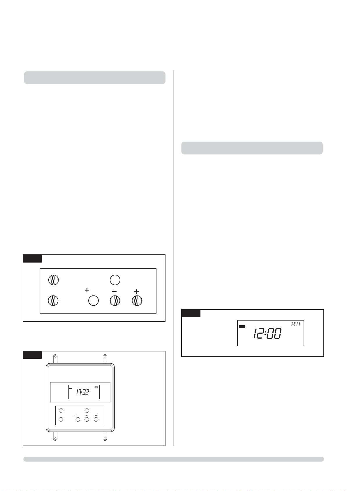
Programmer instructions
1.3 On initial power-up the unit should be re-set to wake up the
unit Remove the programmers button cover, see diagram 2.
To re-set the unit press and hold the four buttons shaded grey,
see diagram 1.
1.3 Diagram 2 depicts how the display will look after being
re-set.
Factory programming.
1.5 The unit can provide up to 3 On/Offs each day. In order to
simplify programming a factory pre-set programme is
included. This can be easily altered to suit household lifestyle
and needs.
Event 1 ON = 06:30 AM OFF = 08:30 AM
Event 2 ON = 12:00 PM OFF = 02:00 PM
Event 3 ON = 05:00 PM OFF = 10:30 PM
IMPORTANT: This cooker will require approximetly 1
1
/
2
hours to heat up to 220°C from cold. This must be taken
into consideration when programming for cold start.
2.1 Remove white protective cover from base of programmer.
2.2 Activate programmer, pressing four buttons (select, advance
and +plus - minus) together.
2.3 12.00 will appear in window either - 12.00a.m or 12.00p.m.
2.4 Press programmer button.
2.5 Press +plus or minus buttons to adjust time to AM or PM.
2.6 Press programmer button.
2.7 To set on/off times refer to Setting event times.
Programming the units, 24 hour operation.
Setting the time of day.
2.8 Remove the programmers button cover. Press PROG to enter
programming mode. The display will be as in diagram 2 and
the colon in the display will not flash.
2.9 Press and release the + or - button to change the time in
one minute increments. Note: If the button is held down, the
time will change in increments of 10 minutes.
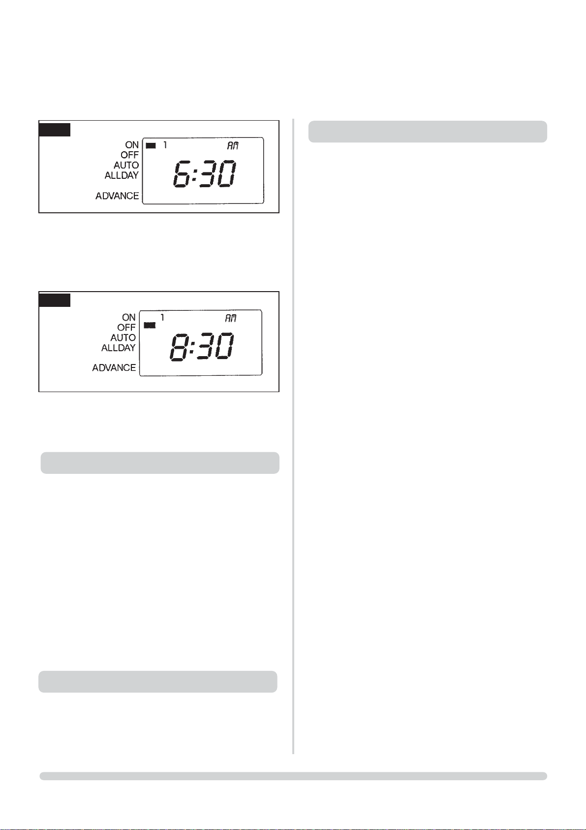
2.10 Setting event times.Press PROG to advance to the next step.
The display will be as in diagram 4.
1. OPERATING
2. SETTING THE TIME
SELECT PROG
ADV
1 HR
1
3
2
SELECT PROG
ADV
1 HR
ON
OFF
AUTO
ALLDAY
+ 1 HOUR
ADVANCE
UNIT WITH PROGRAMMING
COVER REMOVED
ON
OFF
AUTO
ALLDAY
+ 1 HOUR
ADVANCE
6
USER INSTRUCTIONS
2.11 Press and release the + or - buttons to change event 1 ON
time in increments of one minute. Note: If buttons are held
down, the time will change in increments of 10 minutes.
2.12 Press PROG again to select event 1 OFF time. The display
will be as in diagram 5.
2.13 Repeat steps A, B and C above for event 2 ON/OFF times
and again for event 3 ON/OFF times before pressing PROG
again to return to RUN mode. Having finished programming,
replace the programming button cover.
3.1 Use the Cooker SELECT button to select between:
•ON Run continuously
•OFF Off continuously
•AUTO Follows programme
•ALLDAY Turns on first programmed ON
event and off at end of last
programmed OFF event.
•Use ADV or +1HR to override
programmes.
•ADV Advances unit to next event.
•+1HR Adds 1 hour onto end of current
programme.
4.1 In the event of a power failure the time and programmed
events will be retained for up to 14 days, after which the unit
will go into sleep mode, and will need to be reprogrammed
when the power is restored (refer to Initial Power-Up at
beginning of instruction).
5.1 The Hotplate area is protected with two insulated lids which
should remain in a closed position when the cooker is not in
use. The lids can be raised independently if only using one
hotplate. The cooker has two hotplates which are controlled
by the top oven thermostat. The design of the hoplates allows
the heat distribution to the left hand hotplate to reach a rapid
boil facility, suitable for deep fat frying, shallow frying and
boiling. Whereas the right hand hotplate will allow you to
simmer. Depending on what temperature the thermostat is set
at will determine the heat in the hotplate.
5.2 The surface of the hotplates are ground flat and it is therefore
recommended that all utensils used have a solid, flat base to
come in complete contact with the hotplate for efficient
results. From a cold start it will take approximately thirty minutes
for the hotplate to reach a working temperature with the
thermostat set at 180°C. With the thermostat set at 180°C the
left hand hotplate will be suitable for bringing foods to the
boil, to shallow or deep fat fry a temperature setting of 200°C
to 220°C should be selected. Both hotplates will hold three
150 mm. Saucepans at the same time. The hot plate
surround will clean easily when cool or cold, just wipe away
any immediate spillage and deal with it later. The cast iron
hotplates will carbonize any spillage.
5
3. USING COOKER SELECT BUTTON
4. BATTERY BACKUP
5. THE HOTPLATE (S)
4
7
USER INSTRUCTIONS
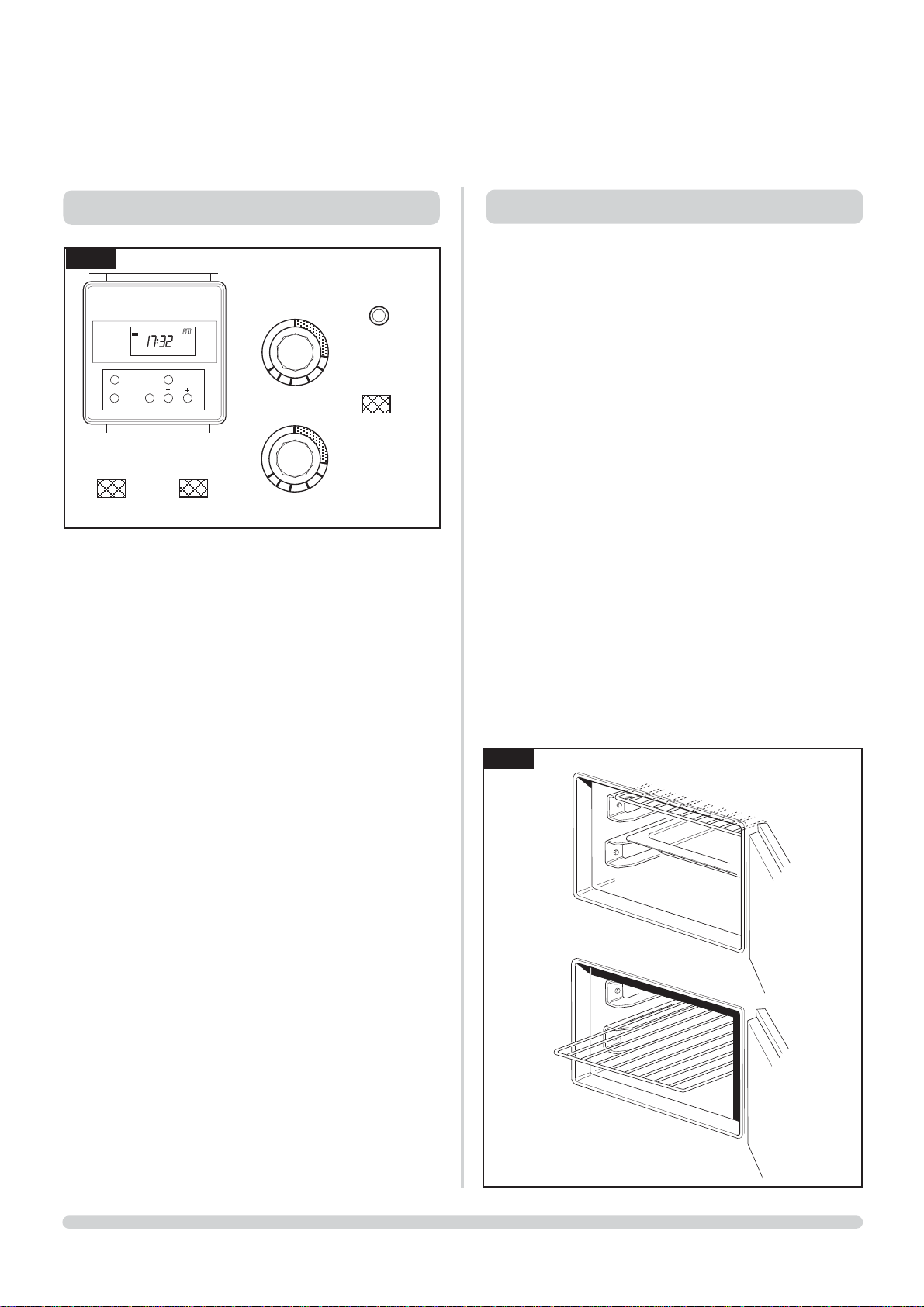
Top Oven Control
6.1 This single thermostat controls the centre oven temperature of
the top right hand oven which also controls the heat
distribution to the hotplates and bottom oven.
6.2 With the programmer ON either timed or auto, the indicator
light will be illuminated red. Now turn the Gas Oven Control
to the desired temperature setting, simultaneously an orange
neon will illuminate above the controls door indicating that
the gas burner has automatically lit. When the oven has
reach the desired temperature the neon will go off, and food
can be placed in the oven.
7.1 As stated in the CONTROLS section, the oven is heated by
either setting the programmer to ‘AUTO’ and having the
thermostat pre-set (at say 180°) or by running it manually and
turning the thermostat up or down to the desired
temperature. Remember however to allow heat-up time, as
much as 1
1
/2 hours to reach 220°C from cold. The thermostat is
calibrated to the centre of the oven and as any convential
oven, the top oven shelf position will be hotter than the
lower.
7.2 As a heat storage cooker, so you will find as the flue gases
pass between the ovens, they will heat the base of the top
oven, allowing you to cook on the floor of the oven. Ideal for
providing bottom heat for foods such as quiches, pastries,
pizzas etc.
7.3 The oven shelf provided can be used in four different
positions.
7.4 To grill in this cooker the thermostat is set to a high
temperature (180°C +) and the foods are placed in the
appropriate container with the oven shelf on either shelf
position 1 or 2, depending on the depth of container. Foods
may take a little longer to grill in this position at the top of the
oven, but they will brown evenly, stay moist and any extensive
steam or fat splashing will carbonize itself away.
7.5 Use the different heat zones to your advantage, cook different
foods at different temperatures in the same oven or when a
recipe states to turn the oven temperature down, due to the
thickness of the oven walls and the high insulation
surrounding it there will be a delay, so use an alternative heat
zone or the bottom oven.
6
6. TOP OVEN CONTROL
ON
OFF
AUTO
+ 1 HOUR
ADVANCE
TOP OVEN
BOTTOM OVEN
ELEMENT ON
RESET
BUTTON
LOCKOUT
LIGHT
140
COOL
0
160
180
200
220
240
160
180
200
220
240
COOL
0
OVER HEAT
STAT
7. TOP OVEN
7
ON
OFF
AUTO
ALLDAY
+ 1 HOUR
ADVANCE
SELECT PROG
1 HR
ADV

8
USER INSTRUCTIONS
8.1 The Bottom Oven is a simmering oven and the design of the
cooker allows this oven to reach simmering temperature
when the top oven is set at 200°C or above and converts to a
warming oven when below this figure. There is an electric
element positioned in the top of this oven and the control is
situated behind the top left hand door, next to the control is
a neon indicator light which will glow until the selected
setting is reached. When using the electric element to boost
the bottom oven to a temperature above simmering
remember this new heat source is now a direct radiant heat
from the element combining with the all round heat of “heat
storage” when the oven is ready for use you must either
protect the food you are cooking or switch off the electric
element, the design of the oven will hold its heat long
enough to cook small items of food, such as biscuits, cakes
and scones. If the recipe being cooked requires a large
period of cooking then use the top oven.
8.2 The Electric element can be used for grilling, although grilling
in the top oven is a more comfortable position for the user,
but if the top oven is full, then the electric element provides
a second grill.
8.3 The bottom oven can work independently form the rest of
the cooker but if using this mode of cooking remember the
heat source comes ONLY from the electric element at the
top and there is no all round “heat storage” heat. Care
should be taken when choosing what foods to cook.
CAUTION - Accessible parts may become hot when the
element is in use. All standard safety precautions must be
adhered to.
Lockout Reset
8.4 The cooker has only one gas burner to power it which is
protected by a safety device. This device monitors the fan
pressure which supports combustion, this will automatically
shut down the main burner if a fault occurs. If the Lockout
reset is illuminated then the pilot has also been extinguished.
To reset simply press the button. The cooker should now
operate normally.
8.5 If the cooker goes to lockout and needs resetting more than
once then it could indicate that there is a poblem with the
ventilation and the oxygen sensitive pilot has turned off the
gas supply to the cooker
Check that the grilled outlets on the top rear splash back
are not covered. If the cooker fails to re-light, try pressing
the reset button again if unsuccessful this should be
inspected by a qualified engineer befor further use of the
cooker.
Overheat thermostat reset
9.1 Meat cooked in a heat storage cooker has very little
shrinkage and rarely requires any additional fat for cooking.
There are two basic methods for roasting meat, to quick roast
at setting 200°C for superior cuts, and for slower roast at
setting 170°C for courser cuts, where muscle has been
worked far more. I would recommend searing or sealing an
inferior cut at a high temperature for approximately 20/30
minutes before reducing the thermostat to the lower setting.
Roast meat will benefit if left to stand when cooked, it allows
the juices to settle and makes for easier carving. Remove to
the lower oven for the this rest period, it will leave the top
oven free for such items as roast potatoes or Yorkshire
pudding. If the lower oven is not free, cover with to keep
warm.To calculate cooking times always take into account
the shape as well as the weight. A small, narrow joint will
cook quicker than a solid, even shaped joint.
9.2 The oven control settings and cooking times given below are
intended to be used as a guide only. Individual tastes may
require you to adjust the control setting either up or down or
to reposition the item being cooked.(If oven temperatures
seem to be abnormal to those stated then the oven
thermostat could be faulty and may require replacing.)
MEAT
Setting Shelf Approx time
Beef with bone - slow 170°C 3 20-25 min per 500g+ 20-25 min
- quick 200°C 3 15-20 min per 500g+15-20 min
Beef boneless - slow 170°C 3 30-35 min per 500g+30-35 min
- quick 200°C 3 20-25 min per 500g+20-25 min
Lamb - slow 170°C 3 30-35 min per 500g+30-35 min
- quick 200°C 3 25-30 min per 500g+25-30 min
Pork or Veal - slow 170°C 3 35-40 min per 500g+35-40 min
- quick 200°C 3 25-30 min per 500g+25-30 min
NOTE : If stuffed and rolled add approximately 10 min per 500g.
All joints must be thoroughly thawed out before cooking.
8. BOTTOM OVEN
9. OVEN COOKING GUIDE
Overheat thermostat reset
8.5 The cooker is protected by an overheat thermostat designed
to shut down the burner if a fault occurs leading to excessive
oven temperatures. To reset the overheat thermostat (located
on the front panel) unscrew the protective cap (if fitted) and
press the button to operate.
NOTE. If overheat reset occurs more than once contact your
registered gas engineer.

9
USER INSTRUCTIONS
Poultry
9.3 Poultry and Game are best cooked on a trivet in a roasting
tin so that the meat does not stew in it’s own juices.
Remember to calculate any stuffing into the cooking time. All
birds must be thoroughly thawed out before cooking.
Casseroles
Cakes
Pastries
9.4 If it is winter time, you can preset the programmer to your
own personal program allowing the cooker to switch on
before you return, when your lifestyle takes you away from
home during the day, or simply to switch on the cooker
before you wake in the morning to a warm kitchen and
breakfast can be prepared quickly. To switch Off if not
required and on again before the family return at the end of
the day to cook the evening meal, and then off just before
you retire. Do not forget this appliance has loads of stored
heat, use it to save fuel accordingly.
IMPORTANT: This cooker will require approximetly 1
1
/
2
hours to heat up to 220°C from cold. This must be taken
into consideration when programming for cold start.
10.1 Choose food carefully when there is a time delay before
cooking commences. Ideally food should be taken from the
refrigerator and placed in the oven and cooked. Never place
hot or warm food from previous usage in the oven for a
delayed cook time.
10.2 Remember there will be no one attending to the food during
cooking, so do not overfill dishes.
10.3 Remember that there are different heat zones in the oven
and place the food on the correct shelf position.
10.4 Perishable foods should be very fresh.
10.5 Protect food, wherever possible with a lid or aluminium foil.
IMPORTANT: Keep the delay cook time as short as
possible, given the right conditions of food, moisture and
warmth bacteria will rapidly multiply.
THE MAIN REASON FOR FOOD POISONING IS THE
STORAGE OF HIGH RISK FOOD AT ROOM
TEMPERATURE.
Setting Shelf Approx time
Rich fruit cake 140-150°C 4 Approx guide line 45 min
Victoria sandwich 180°C 3 per 500g of mixture.
180-230 mm 200mm
(7-8”) tin, 2-3 hr.
Queens cakes 180-190°C 2
(2 trays) 3 15-25 min
Scones 200°C 2 10-15 min
Setting Shelf Approx time
Shortcrust 220°C 4 According to recipe
Flaky 220°C 2 According to recipe
Rough puff 220°C 2 According to recipe
Puff pastry 220°C 2 According to recipe
Setting Shelf Approx time
Chicken 170°C 3 20-25 min per 500g+ 20-25 min
Turkey
up to 4.5kg
- slow 170°C 3 15-20 min per 500g+15-20 min
- quick 200°C 3 15-20 min per 500g+15-20 min
Turkey
over 4.5kg - quick 170°C 3 30-35 min per 500g+30-35 min
- quick 200°C 3 20-25 min per 500g+20-25 min
Duck 170°C 3 30-35 min per 500g+30-35 min
Goose 170°C 3 35-40 min per 500g+35-40 min
Setting Shelf Approx time
Top oven 140-150°C 3 Hours according
to recipe
Fish oven baked 180°C 2 According to size, cut,
preparation, and recipe.
10. COLD START COOKING

10
USER INSRUCTIONS
IMPORTANT:
Never use caustic, citric, or abrasive cleaners as these will
scratch or damage the surface.
11.1 Always try to wipe up any spillages when they occur.
11.2 A more satisfactory result will be achieved if the cooker is
cool when cleaning.
11.3 Use hot soapy water and a cloth for the enamel, drying with
a soft dry cloth after to avoid streaking.
11.4 To clean the ovens simply wire brush any stubborn carbon
stains and vacuum away the deposits. Using a wire brush can
scratch the surface of the oven but this is not detrimental.
The surfaces of the oven are natural, therefore to prevent
oxidation dry all surfaces after cleaning.
Top plate
Hot plate dome chrome
Hot plates
Oven
Chrome Shelves
Oven door
Door Liner
Seal
Colour parts
Front
Sides
Doors
Chrome handles
Towel rail
Hot water & soap
Wire brush
Cream cleaner VE Approved
Nylon brush
✓
✓
✓
✓
✓
✓
✓
✓
✓
✓
✓
✓
✓
✓
✓
✓
✓
✓
11. CARE OF THE COOKER

11
HEALTH AND SAFETY
INFORMATION FOR THE INSTALLER AND SERVICE ENGINEERS
Under the Consumer Protection Act 1987 and the Health and Safety at Work Act 1974, it is a requirement to provide information on
substances hazardous to health (COSHH Regulations 1988).
The Company takes every reasonable care to ensure that these products are designed and constructed to meet these
general safety requirements, when properly used and installed.
To fulfil this requirement products are comprehensively tested and examined before despatch.
This appliance may contain some of the items below.
When working on the appliance it is the Users/Engineers responsibility to ensure that any necessary personal protective
clothing or equipment is worn appropriate to parts that could be considered as being hazardous to health and safety.
INSULATION AND SEALS
Glass Rope, Mineral Wool, Insulation Pads, Ceramic Fibre, Glass Insulation.
May be harmful if inhaled. May be irritating to the skin, eyes, nose or throat. When handling avoid inhalation
and contact with eyes. Use (disposable) gloves, face masks and eye protection.
After handling wash hands and other exposed parts. When disposing, reduce dust with water spray,
ensure parts are securely wrapped.
GLUES, SEALANTS & PAINT
Glues, Sealants and Paints are used in the product and present no known hazards when used in the manner
for which they are intended.

12
INSTALLATION AND SERVICING
Health & Safety (Information for the Installer and Service
Engineer.) Under the Consumer Protection Act 1987 and the
Health and Safety at Work Act 1974, it is a requirement to provide
information on substances hazardous to health (COSHH
Regulations 1988).The Company takes every reasonable care to
ensure that these products are designed and constructed to meet
these general safety requirements, when properly used and
installed. To fulfil this requirement products are comprehensively
tested and examined before despatch.
This appliance may contain some of the items below. When
working on this appliance it is the Users / Engineers responsibility
to ensure that any necessary personal protective clothing or
equipment is worn appropriate to parts that could be considered
as being hazardous to health and safety.
Insulation and Seals
Glass rope, Mineral wool, Insulation pads, Ceramic fibre, Glass
insulation. May be harmful if inhaled. May be irritating to the skin,
eyes, nose or throat. When handling avoid inhalation and contact
with eyes. Use (disposable) gloves, face masks and eye protection.
After handling wash hands and other exposed parts. When
disposing, reduce dust with water spray, ensure parts are securely
wrapped.
Glues, Sealants and Paint
Glues, Sealants and Paints are used in the product and present no
known hazards when used in the manner for which they are
intended.
Safety Regulations
This appliance shall be installed in accordance with the regulations
in force and only in a well ventilated space. Read the instructions
before installing or using this appliance.
The installation of this Redfyre must be carried out by a
competent person in accordance with the relevant
requirements of the Gas Safety (Installation and Use)
Regulations 1998 and this person must be a gas registered
engineer.
The person(s) who installs this appliance, services or
carries out any remedial work, i.e. electrical fault finding,
must have suitable engineering qualifications.
All relevant British Standards, Codes of Practice, in particular :
• BS 5440 Part 2 : 1989 Specification for installation of
ventilation for gas appliances.
• BS 6172 : 1990 Specification for the installation of domestic gas
cooking appliances (1st, 2nd and 3rd family gases).
• BS 6891 : 1988 Specification for installation of low pressure gas
pipework of up to 28mm (R1) in domestic premises
(2nd family gases).
Ventilation requirements
The room containing the cooker should have an air supply in
accordance BS 5440 Part 2 : 1989. All rooms require an openable
window or equivalent, while some rooms require a permanent
vent in addition to the openable window. The cooker should NOT
be installed in a room containing a shower, bath or a bedsitting
room with a volume less than 20m
3
. If it is installed in a room of
volume less than 5m
3
an air vent of effective area 100cm2is
required. If it is installed in of volume between 5m
3
and 10m3, an
air vent of effective area 50cm
2
is required. However, if the room
has a door that opens directly to the outside, no air vent is required
even when the room volume is between 5m
3
and 10m3.
If there are any other fuel burning appliances in the same room in
which the cooker is to be installed, then BS 5440 Part 2 : 1989
must be consulted to determine the correct air vent requirements.
The use of a gas cooking appliance results in the production of
heat and moisture in the room in which it is installed. Ensure that
the kitchen is well ventilated: keep natural ventilation holes open
or install a mechanical ventilation device (mechanical extractor
hood) Prolonged intensive use of the appliance may call for
additional ventilation, for example opening of a window, or more
effective ventilation, for example increasing the level of
mechanical ventilation where present.
Loose parts
Check the following loose parts are enclosed :
Oven shelves - 3 Off.
Oven shelf plain
Roasting tin
Hand rail
Hand rail bracket - 2 Off
Hand rail washers - 2 Off
Hand rail securing screws - 2 Off
Front kick strip
Side kick strips - 2 Off
Front and side kick strips securing screws - 4 Off
Stability Chain - 1 Off
Wall Hook - 1 Off
Hand Rail
The Hand Rail is held in position by the two hand rail brackets
secured at each end of the front top plate. Secured in position
with the bolt supplied. The washer is trapped between the hand
rail bracket and the front of the top plate to prevent the enamel
from scratching. Fit one hand rail bracket in place with screws
facing down then insert the hand rail itself and fix the other
bracket holding the rail in place. Secure the hand rail to the
bracket with the two 3mm Allen screws provided.
Cooker mobility
The cooker has been designed with mobility in mind. However
even though there are built in trucking wheels it may be still
necessary to use extra help. Although the wheels are nylon great
care should be taken when manoeuvring the cooker over different
floor coverings.

13
INSTALLATION AND SERVICING
Cooker standing plinth or base.
The weight of this cooker (335Kg) is distributed onto 4 corner
supports - it is important that the floor is level and capable of
supporting the loading - additional support may be required.
Cooker clearances.
• The cooker is designed to fit in a 1000mm gap with a 10mm
clearance gap each side.
• If the R/H side of the cooker is to positioned next to a wall then
an extra 100mm is required at the right hand side.(for oven
shelf removal.)
• A clearance above the cooker of 550mm is required for the
raising of the Hotplate lids. If a cooker hood is to be fitted then
it should be installed to the manufacturer’s instructions.
• We recommend that at least 1000mm is left in front of the
cooker to aid cooking and servicing.
• Overall dimensions: Height 900mm
Width 976mm
Depth including towel rail 700mm
Towel rail 80mm
Stability Chain
Because the cooker is installed on a flexible gas connection, the
stability chain must be fitted. See diagram.
Cooker stability
With the plinth or floor already levelled push the cooker into its
intended position. There are two locking screws located at the
front corners of the base plate to lock the cooker in position before
the front kicking strip is fitted.
Kicking Strip Fitting
Fit the two side kicking strips with the (4) securing screws supplied
in holes in the base sides. Fit the front kicking strip with (2)
securing screws in the holes in the front edge of the base.
Gas Connection
The 1/2Rp. BSP elbow gas connection is located just below the
top at the right hand rear of the cooker (see diagram page 16).
Connect the gas supply to the 1/2Rp BSP elbow. To aid
installation, mobility and servicing we recommend the use
of a 1.2m - 1.5m long BSP flexible connection to BS 669.
With a flexible hose installation the maximum height for gas
supply outlet secured to the wall must be 600mm. The hose,
should also be fitted that both the inlet and outlet connections are
vertical, so that the hose hangs down. After connection test the
installation from the meter to the gas cock for gas soundness and
purge in accordance with BS6891.(To gain access to the gas cock
remove the panel behind the bottom left hand door.)
1
2
3
STABILITY CHAIN
COOKER STABILITY
Type Gas Inlet Step Burner Max Burner Gas
Rate Cat Pressure Pressure Pressure Input Injector gm /h
Nat Gas I
2H
20mbar - 10mbar 7kw ø2.24mm -
LPG I
3+
28-30/37 - 28-30/37 7KW ø 1.3mm 509/500

14
INSTALLATION AND SERVICING
Electrical connections
All external wiring to the appliance MUST in accordance with the
current IEE Wiring Regulations, Electricity at Work Regulations
and any Local Regulations.
The appliance is supplied for 230v ~ 50 Hz.
The total power consumption is : 1.16kW.
Fuse rating is 7A. external.
The method of connection to the mains supply Must facilitate
complete electrical isolation of the appliance. This can be
achieved by plugging into a non switched socket. The cooker is
supplied with a 2 metre (3 x 1mm core PVC flexible cord to BS
6500), a fitted plug with a 7 amp fuse. If the supply cord is
damaged, it must be replaced by the Redfyre or Redfyre service
agent or a similarly qualified person on order to avoid hazard.
Should the plug on the flexible cord not be the type for your socket
outlets, do NOT use any adaptor, but remove the plug from the
cord and discard. Carefully prepare the end of the supply cord
and fit a suitable plug.
WARNING : THIS APPLIANCE MUST BE EARTHED.
The wires in the mains lead are coloured in accordance with the
following code:
Green/Yellow Earth
Blue Neutral
Brown Live
As the colour of the wires in the mains lead of this appliance may not
correspond with the coloured markings identifying the terminals in
your plug, proceed as follows:
The wire which is green/yellow must be connected to the terminal
in the plug marked with the letter E or earth symbol, or coloured
green/yellow. The wire which is coloured blue must be connected
to the terminal which is marked with the letter N or coloured
black. The wire coloured brown must be connected to the
terminal which is marked with the letter L or coloured red.
The mains lead, plug and socket must not be directly exposed to flue
products emitted from the top rear grill, or be in contact with any
hot surfaces. The lead must not be trapped or pulled taut when
the appliance is pushed into position. When the appliance is
positioned the plug must be accessible.
Plug in the appliance and then turn on the electricity supply. If
there is fault for any reason carry out the following checks:
Electrical Checks:
Earth Continuity check
Isolate the electrical supply to the appliance. Set your meter on
the W(ohms)X1 scale and adjust zero if necessary. Test leads from
appliance earth points (earth points can be found at the rear of the
bottom LH door controls panel accessed by removing the securing
screws), to the earth pin on the plug. The resistance should be less
than 1W(ohm), check all wires for continuity and all contacts are
clean and secure.
Polarity Check
Turn ON the mains supply and with your meter set on 300V AC
scale and test at the appliance terminal strip. (the terminal strip
can be found behind the bottom LH door control panel accessed
by removing the securing screws. Test leads from L to Earth, and N
to Earth to establish polarity.
4

15
INSTALLATION AND SERVICING
Redfyre Wiring diagram
fitted with SIGMA gas Valve

16
INSTALLATION AND SERVICING
Hotplate adjustment
If hotplate adjustment is required then access to adjustment screws
is made available by removing the stainless steel surround held in
position by 5 Allen key screws.
Each hotplate has 3 adjustment screws for levelling, the boiling
plate (Left hand) should be 1.5-2.0mm below the level of the
stainless steel surround. This is to allow the plate to expand when
hot. The simmering hotplate (right hand) should be level with the
stainless steel surround.
NOTE: The lifting handle should always face to the side of the
cooker if the hotplate has been removed for any reason.
The lifting weight of the Boiling plate = 31 kg.
Simmer plate = 21 kg.
Care should be taken when lifting out the hotplate not to damage
the enamel surfaces.
Burner Control System (Normal operation)
On demand for heat via the thermostat the power is supplied to
the Air Pressure Switch, which providing that the fan has
established adequate air flow, makes contact. Power is then fed to
the ignition control board. The control board waiting time (1.5s)
establishes that there is no parasitic flame present, and that the
internal control circuit is operating correctly. After the waiting time
the built in igniter and pilot solenoid are energised. This
commences the safety time (60s). The ignition spark will ignite the
gas and the flame will be sensed by flame rectification on the
ignition electrode. The main solenoid will then open and the
ignition suppressed. When the thermostat is satisfied the control is
switched off. Failure to ignite the pilot within the safety time will
result in the control going to lock out mode. To reset the unit the
reset button will have to be pressed. If a first reset is not successful,
wait at least 10 seconds before the next attempt.
Installation Check List
To be completed by the Installer
Please Tick
1. Satisfactory ventilation
(see installation - service instructions)
2. Check that the Stability Chain is fittedl
(see installation - service instructions)
3. Gas burner tested and ignition tested
(see gas connection instructions and data plate for
gas pressure settings)
4. Electric oven function checked
(see users instructions)
5. Programmer function check
(see users instructions)
6. Full electrical check made
(see electrical section)
7. Full gas soundness check made
(BS 6891)
8. Has customer been instructed in use
Y N
5

17
INSTALLATION AND SERVICING
General
The servicing of the Redfyre must be carried out by a competent
person in accordance with the relevant requirements of the Gas
Safety (Installation And Use) Regulation 1998: and this person
must be a gas registered engineer, and a qualified electrical
engineer.
NOTE: It is impossible to service the Redfyre while it is hot, the
customer must be informed that to switch off the cooker 12 hours
before a service is required. Your Redfyre requires servicing
every 12 months.
It is important that only the correct Redfyre part is obtained
from a Trianco Redfyre direct or authorised dealer.
When servicing or replacing any components :-
1. Isolate the gas supply.
2. Isolate the electrical supply.
3. Reassemble all components in reverse order.
4. Check for gas soundness after servicing or replacing
components.
5. Before electrical reconnection carry out checks for earth
continuity, short circuiting and polarity.
6. General access to controls are found behind the two left hand
doors. The control panels are removed by removing their (4)
securing screws.
7. To move the cooker forwards for rear access, remove the front
kick strip secured with screws. When removed screw up the two
locking screws located at each front corner of the base plate.The
cooker can now be pulled carefully forwards, the flexible gas
connection can now be disconnected and if necessary the securing
chain removed.
To remove the Gas control assembly, the following components
can be replaced, Gas valve, Ignition lead, Pilot assembly, Main
burner and Main burner injector.
With the bottom control panel removed. Turn off the gas cock,
unscrew the union to break the gas supply. Remove the lint guard
secured with (2) nuts. Partialy withdraw the gas valve assembly, to
gain access to the screw securing the PCB to the gas valve, remove
screw. Remove PCB by sliding the PCB to the left off the gas valve.
The PCB can now be unplugged if required on the Molex plug.
All components can now be exchanged or serviced.
Gas valve removal.
Unscrew the pilot tube from the gas valve.
Disconnect the gas valve at the flange joint by removing securing
screws.
Unscrew the inlet pipe.
On replacing it is advisable to use new ‘O’ ring, and thread sealant
for the inlet pipe connection.
Gas valve solenoid removal.
Remove securing screw and slide out solenoid assembly.
Pilot assembly removal.
Remove the ignition lead from the igniter post.
Unscrew the pilot gas pipe at the pilot and pilot injector.
Unscrew the pilot from its supporting bracket.
Ignition lead removal.
Remove the ignition lead from the ignition.
Remove the ignition lead from the igniter.
Withdraw the ignition lead from the combustion chamber door.
On reassembly use the protective sleeving to ensure it covers the
base of the igniter post.
Main burner and main burner injector removal.
Unscrew the pilot at its support bracket.
Unscrew the (2) securing nuts which hold the main burner to the
combustion door and remove the burner.
Unscrew the main burner injector.
(Only clean by blowing air through.)
Ignition board removal
With the bottom control panel removed.
Turn off gas cock,
unscrew the union to break the gas supply.
Remove the lint guard secured with (2) nuts.
Partially withdraw the gas valve assembly, to gain access to the
screw securing the PCB to the Gas valve, remove screw.
Remove PCB by sliding the PCB to the left off the gas valve.
The PCB can now be unplugged if required on the Molex plug.
1. SERVICING PROCEDURE
6

18
INSTALLATION AND SERVICING
Thermostat removal
With the upper control panel removed.
Either of the thermostat can be removed by pulling off the control
knob.
Unscrew the securing nut.
Removing the electrical push on connectors.
Disengage the thermostat phial from its bracket found at the top
front edge of each oven. The gas control thermostat is located in top
oven the and the electric boost in the lower oven.
Programmer removal
With the upper control panel removed.
Unscrew the programmer securing.
Disconnect the electrical connections to the programmer.
Element and lockout Neons removal
With the upper control panel removed.
Disconnect the electrical connections to the Neon.
Release the neon from the panel.
Reset button removal
With the upper control panel removed.
Disconnect the electrical connections to the reset button.
Release the reset button from the control panel.
Top oven neon removal
The top oven neon is positioned above he top left hand door.
To remove, unscrew the securing screws holding the decorative
plate.
Disconnect the electrical connections to the neon.
Release the neon from the decorative plate.
Fan and Air pressure removal
With the cooker pulled forward.
Remove the right hand rear panel with air in take holes at the
base,
secured by screws.
To remove the Air pressure switch disconnect the electrical
connections.
Remove the air sensing tube from the (-) negative connection.
Remove the air pressure switch securing screws.
To remove the Fan (you first must remove the air pressure switch.)
Disconnect the electrical connections to the fan.
Remove the (2) fan mounting plate screws and slide the fan down
to disengage the fan outlet.
Remove the (3) fan securing screws.
Electric element removal
With the cooker pulled forward remove the left hand rear panel and
insulation to expose the element junction box.
Disconnect the electrical connections.
Remove the electric element guard secured by (4) screws in the
bottom oven.
Remove the central screw securing the element to the rear wall of the
oven.
Hot plate lid removal
There is an Allen key screw in each hinge support bracket that
retains the pivot rod. To remove the rod loosen Allen key screws
and gently slide out the rod.
Hot plate lid liner removal (Square lids)
It is possible to remove the lid liner in situ, but it easier if the hot
plate lid has been remove.
To replace remove the corner securing screws.
Hot plate lid seal removal (Square lids)
It is possible to remove the lid seal in situ, but it easier if the hot
plate has been remove.
Remove the lid liner secured by corner screws.
Remove the seal.
Hot plate lid handle support & Spring handle removal.
To remove the Spring handle simply compress the spring and ease
off the handle support peg.
To remove Hot plate lid handle support.
Remove the hot plate lid.
Remove the lid liner secured by corner screws.
Remove the seal.
Remove handle support secured by nut and washer.
Oven door removal
Open door and carefully lift off hinge supports.
Oven door liner removal
Remove oven door carefully.
Remove oven door liner secured by (2) screws.
Oven door seal removal
Remove oven door carefully.
Remove oven door liner secured by (2) screws.
Remove door seal.
Oven door handle and Spring removal
Remove oven door carefully.
Remove oven door liner secured by (2) screws.
Remove door seal and insulation.
Remove inner door plate retained by (4) nuts and washers.
Remove spring securing screw.
Remove door handle pivot screw, washer and nylon spacer washer.
2. COSMETIC PARTS AND SEALS
7

19
INSTALLING AND SERVICING
Remove door handle spring retaining nut, washer, and Spring.
Slide Door handle through slot.
Control door handle and spring removal
Remove control door carefully.
Remove door handle cover secured by (2) nuts and washers.
Remove spring securing screw.
Remove door handle pivot screw, washer and nylon spacer washer.
Remove door handle spring retaining nut, washer and Spring.
Slide Door handle through slot.
8
FAN
EV2 Coil
Open
EV1 Energised
Via Ignition PCB
Programmer
Input 230V
Air Pressure
Switch
Pilot Flame
Detected
Top oven
Thermostat/
Limit thermostat
Functional Flow Diagram

20
REDFYRE FAULT FINDING
NO
RESET BUTTON
REQUIRES PRESSING
START
YES
YES
YES
YES
NO
NO
NO
YES
YES
NO
NO
NO
NO
YES
YES
YES
IS THE RESET LED
ILLUMINATED
CHECK POWER IS ON TO COOKER
(BOTTOM LIGHT WILL ILLUMINATE
IF OVEN IS SWITCHED ON)
SWITCH ON PROGRAMMER TO ON
IS THE RED LIGHT ILLUMINATED
CHECK POWER SUPPLY
AND 7 AMP FUSE
CHECK OPERATION
OF PROGRAMMER
IS THE TOP OVEN
ORANGE TEMPERATURE
INDICATOR ILLUMINATED
CHECK OPERATION OF
TOP OVEN THERMOSTAT
IS THERE 230V ON
TERMINAL W2
CHECK AIR
PRESSURE SWITCH
CHECK CONDITION
OF IGNITION LEAD
AND ELECTRODE
IS THE PILOT
ORIFICE BLOCKED
CLEAN/REPLACE
PILOT ORIFICE
IS THERE 230V BETWEEN
TERMINALS 1 AND 2 ON
GAS VALVE PCB
CHANGE
GAS VALVE
CHANGE IGNITION
PCB
CHANGE
GAS VALVE
CHANGE
IGNITION VALVE
YES
YES
YES
YES
NO
NO
DOES THE IGNITION
BOARD CLICK
WHEN PILOT IS LIT
NO
CHANGE IGNITION
CONTROL BOARD
NO
CHECK CONDITION
OF ELECTRODE
AND LEAD
NO
CHANGE PCB
DOES THE PILOT
LIGHT
IS THE IGNITION
BOARD CLICKING
IS THERE A SPARK
ON THE ELECTRODES
IS THERE 230V BETWEEN
TERMINALS 3 AND 4 ON
GAS VALVE PLUG (ON PCB
)
IS THE FAN RUNNING
CHANGE THE FAN

21
SPARE PARTS LIST
Description Part Number
General NAT GAS LPG
Gas Valve 603251
Gas Valve Solenoid 603253
Pilot Assembly P10039 P10040
Ignition Lead 602304
Main Burner 602284 600824
Main Burner Injector 602316 ø 2.24 602172 ø 1.3
Ignition Board 603252
Thermostat 602277
Programmer 602209
Element Neon 602313
Lock Out Neon 602313
Top Oven Neon 602275
Fan 602273
Air Pressure Switch 603256 / 602274
Electric Element 600822
Hotplate Lid Black 601361 Square Lids 602458 Round Lids
Hotplate Lid Chrome 601371 Square Lids 602457 Round Lids
Hotplate Lid Liner 600553 Square Lids 602459 Round Lids
Hotplate Lid Seal 600705 Square Lids 601482 Round Lids
Hotplate Lid Handle Support 600703
Spring Handle Chrome 600707
Oven Shelf 600682
Oven Shelf Plain 600613
Oven Door Liner 600554
Oven Door Seal 602114
Oven Door Handle Chrome 602096
Control Door Handle Chrome 602097
Door Spring 602088
Top Oven Limit Thermostat 602473

What the guarantee covers
Our customer service department will arrange to have your cooker repaired or replace free of charge any defect or
component that is due to faulty material or workmanship, provided that such a defect occurs within 12 months of the
purchase or 18 months from manufacture, but excludes the replacement of any decorative parts, trims, door catches, towel
rail, and any external surfaces or casing panels and that:
1. Our service department is notified promptly of any defects under the terms of guarantee. The appliance must be made
available for service during normal working hours.
2. The appliance is installed in accordance with these instructions.
3. The guarantee does not apply if the appliance is repaired or modified by any other person other than a member
recommended by our service department. The guarantee does not cover misuse or improper installation.
Before calling for service please check the following:
1. Is there a power failure? Turn on the appliance to check the mains supply.
2. Check that the fuse has not blown.
In the event of service being required the following information will be required by our service department:
1. Your name, address, post code.
2. Telephone number, home and work.
3. The serial number of your cooker and colour of the appliance.
4. Precise details of the fault.
5. Date of purchase.
Please note that when our service engineer visits he will require to see your proof of purchase date, so please retain your
receipt.
WARRANTY CALLS
22

23
Installed by (Corgi)
Registered Engineer
BLOCK CAPITALS
Company Name
& Address
Tel. No.
BLOCK CAPITALS
Signed
Date of installation

Redfyre Limited, Osprey Road, Sowton Industrial Estate, Exeter, Devon, England EX2 7JG
Tel: (01392) 444070 Fax: (01392) 444804 E-mail: redfyre@gazco.com
A Division of Gazco Limited
 Loading...