


Manual up2you-ARF
No.: 9761586 / 9756095
Content:
1. Introduction ........................................................................................................................ 2
2. Unpacking and First Assembly ............................................................................................ 3
3. Attachment of the Winglets ............................................................................................... 5
4. Integration of RC Components ........................................................................................... 7
5. Installation of Motorization Parts in the Electro-Section ................................................. 15
6. Adjustment of Center of Gravity (CG) and Elevons .......................................................... 19
7. Flying ................................................................................................................................. 26
8. For technical interested Modellers ................................................................................... 31
9. General Informations ......................................................................................................... 36
1

1. Introduction
The up2you-ARF is based on a series of predecessors which have been developed during the
last 20 years.
The main geometry data has been changed several times in order to optimize them for a
tailless wing in this size and weight.
The model has on optimized lift distribution and an airfoil which suits very well to the speed.
The profiled winglets increase the lift further.
Drag counts could be saved by deleting a “real” fuselage – this increases the gliding
performance of the model.
The mixture of balsawood, plywood, CFRP and GFRP enables a weight optimizes and
accurate construction.
Special attention has been put on an uncritical handling of the model. It can be flown very
slowly but the reaches its best performance with intermediate speed.
The model can be assembled very quickly with the arrestor hooks; therefore, it is well suited
for holydays or mountain hikes or just to fly a quick round after work.
Due to the possibility to install the electro-section between the wings, the pure sailplane is
enhanced to an electro-glider with the possibility to be launched in plain regions without any
further equipment (bungee).
The following assembly times should be considered:
Winglet Arrestment 2 hours
Integration of RC 5 hours
Integration of motor/controller 3 hours
GC and other adjustments 2 hours
2

2. Unpacking and First Assembly
Check if the following parts are included in the package:
Left and right wing
Left and right winglet
Electro-Section
Various small components to assemble
Assemble the wings with the short CFRP (carbon fibre reinforced plastic) connectors. The
arrestor hook must be fully opened – turn it fully to the left with a small screwdriver, refer to
figure 1.
Then slide both wings together and arrest the hook, refer to figure 2. The arrestor hook will
be noticeable latch in the pin of the other wing.
Assemble in the same way the Electro-section between the wings. Use for this the longer
CFRP connectors.
For the assembly of the Electro-glider, two arrestor hooks must be locked, refer to figure 3.
Figure 1, Fully opened Arrestor hook
3
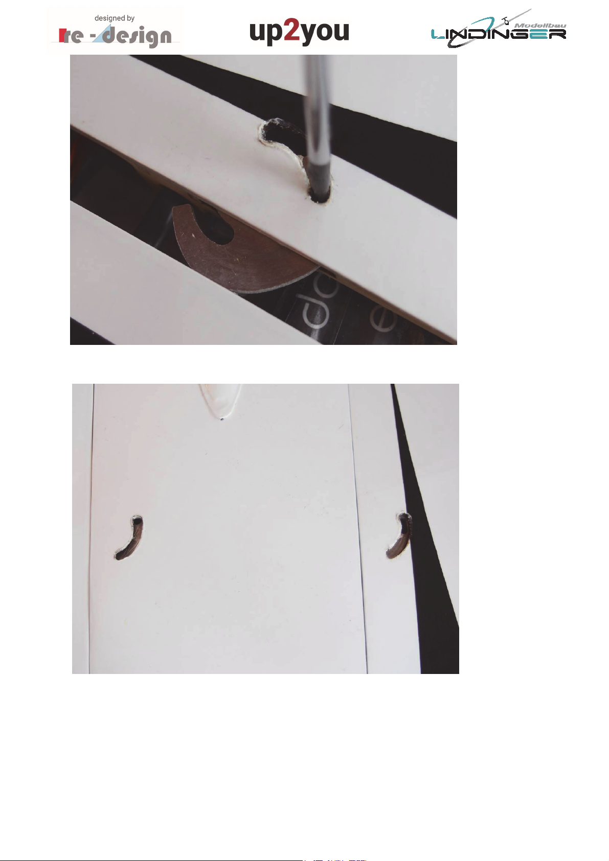
Figure 2, Position of locked arrestor hook (wing not together for demonstration)
Figure 3, Tow arrestor hooks for the electro-glider
4
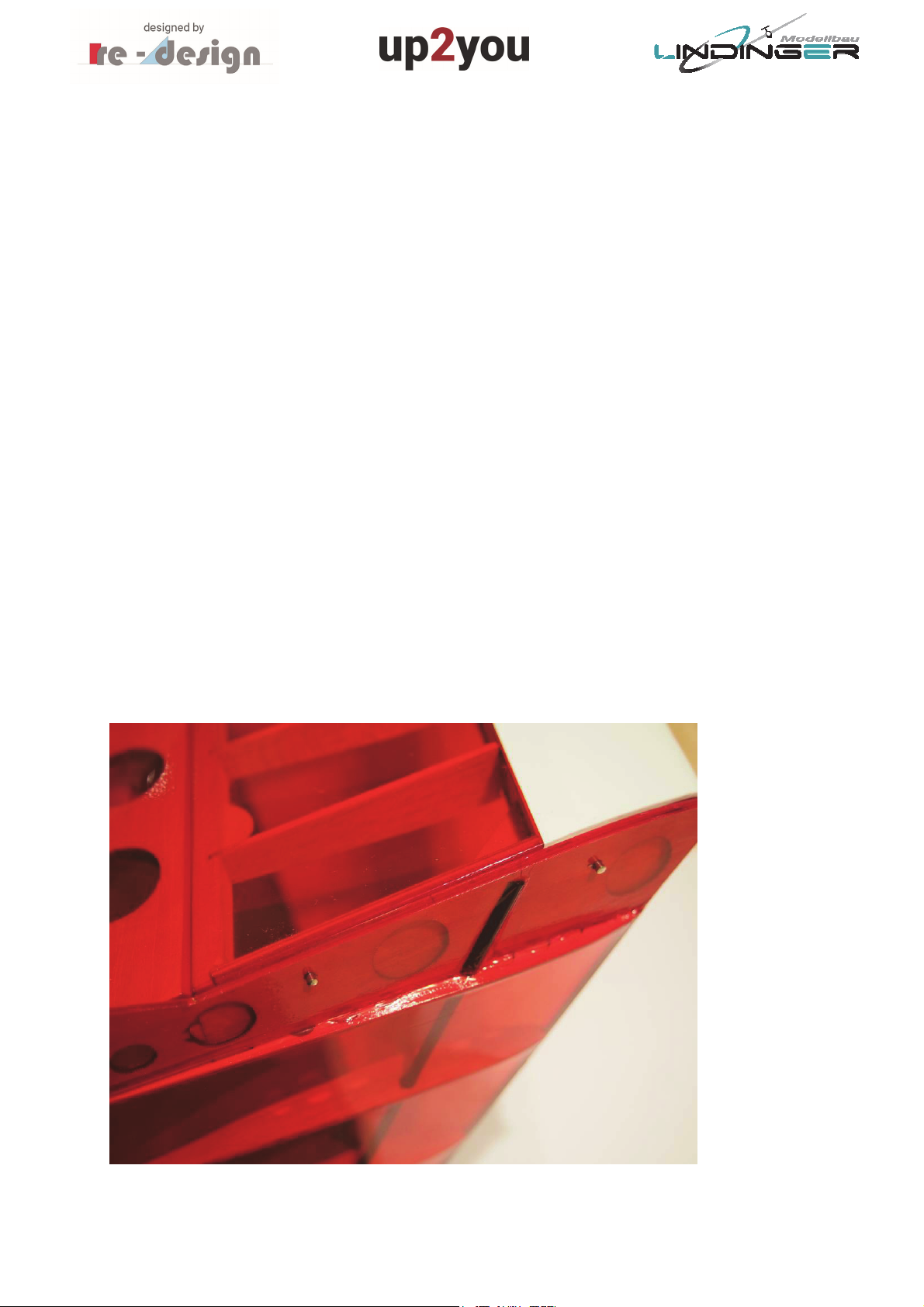
3. Attachment of the Winglets
In order to improve the transport of the glider for example on mountain hikes, the winglets
can be detached from the wings.
They are fixed by a small screw and two pins (2mm diameter, 10mm length). The two pins
must be glued into the baseplate of the winglets.
Before gluing them in the baseplate, they must be cleaned with acetone or thinner. Place
the winglet at its position at the wingtip and hold it. Then insert the pins from the outside of
the baseplate that approx. 5mm will be still visible, refer to figure 4. Ensure that the pins in
this position are already inserted in their bores in the outer rib of the wing.
Now fixate the winglet with the screw at the wing.
Apply epoxy on the part of the pins which are still visible and push them fully into the
baseplate so that they are aligned with the baseplate.
This method ensures that the winglets will be not glued on the outer rib of the wing which
would probably lead to problems to disassemble them.
After the epoxy has been hardened, the winglets can be removed.
Check the correct gluing of the pins by mounting the winglet again on the wing, refer to
figure 5.
Figure 4, Insertion of the winglet pins
5

Figure 5, Winglet correctly mounted on the wingtip
6
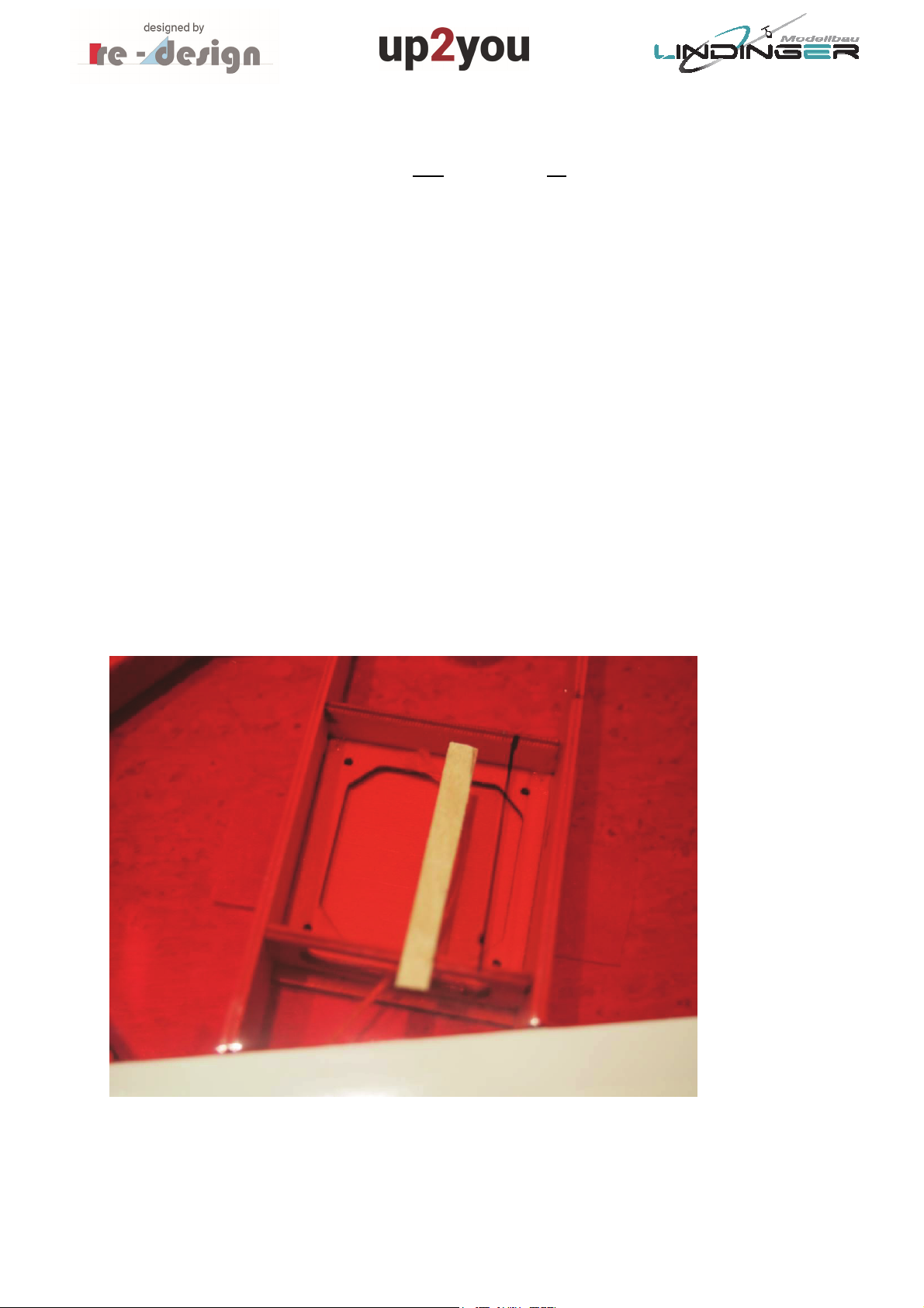
4. Integration of RC Components
The servos for the elevons (shortcut for Elevator and Aileron = combined function of
elevator and aileron) will be on the cover mounted which is fixated with four screws on the
lower surface to the wing. We propose to use the following servo:
ROBBE FS 166 BB MG Digital, #9756143
You may use other servos but the size shall not exceed the following dimensions:
25 x 25 x 9 mm (high x width x depth)
We propose to glue the servos after some adaption work on the cover with just 4 points of
glue. If a servo once fails, it can be easily removed by using a small grinding tool.
The connection from the servo the elevons control horn is on the upper surface of the wing
and therefore, the servo lever must be guided through the shrink film. Mark the cut-out for
the servo lever on the shrink film, refer to figure 6.
In order to achieve a protected edge of the film, you should glue a piece of 1mm plywood
under the cover before cutting out as it is shown in figure 6 and figure 7. Glue the shrink film
at the edge of the cut-out on the piece of plywood by using a modeler iron, refer to figure 7.
Figure 6, Marking of the cut-out for the servo lever
7
Figure
7,
Gluing of the shrink film on the piece of plywood (edge of cut-out)
After the cut-out is accomplished, insert the servo and cover into the wing in order to check
if it fits, refer to figure 8.
Attach the cover on the wing by using two screws. Check if the servo lever you are intend to
use is suitable regarding the length. There must be enough clearance for the clip of the
pushrod under full deflection of the servo.
Now, adjust the servo on its correct position (servo lever should be move more or less
parallel to the ribs) and fixate the servo with a point of glue, as it is shown in figure 9.
Then remove the cover and fixate the servo fully with 4 points of epoxy on the cover, refer
to figure 10.
8

Figure 8, Tentative insertion of the servo in the wing
Figure 9, Fixation of the servo
9

Figure 10, Servos glued on the cover with some points of epoxy
Now the servo cables will be soldered together and installed. You should use preferably very
thin cables in order to save weight. The loads on the servos are very low and therefore there
will be no high current through the cables.
Lengthen the cables should take into account some margin.
Instead of soldering, you may use connectors but we do not recommend this. A well
accomplished soldering connection is better than a connector. Connectors can be a source of
defects. Figure 11 shows the soldered and isolated cables.
Connect the cable to the cord which is inserted by the manufacturer in the wing. Use some
tape in order to have a connection which does not encumber the cable from slipping
through the wing. It is annoying if the connection opens during the installation of the cable –
possibly the wing must cut open if this happens. Figure 12 shows the connection.
Apply soft tension on the cord only. If you have to apply much tension, this could be an
indicator that somewhere the connection clamps in the wing. It is better in this case to pull
the cable a little bit back and then start again.
10
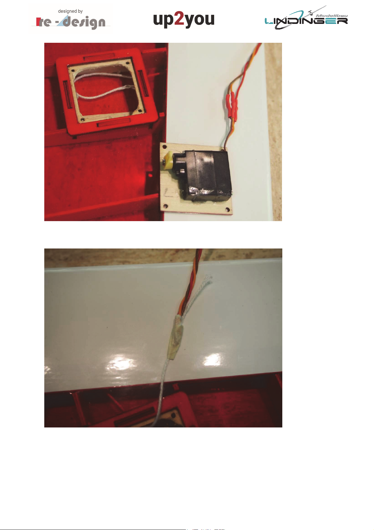
Figure 11, Cables soldered to the servos and isolated
Figure 12, Connection between the cable and the cord
11

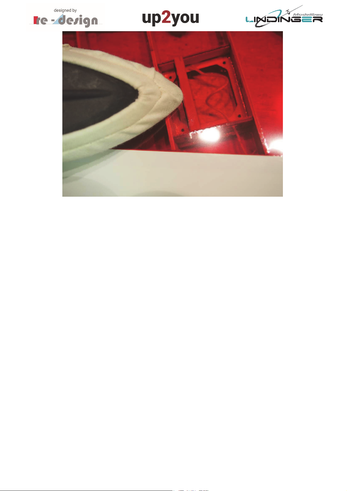
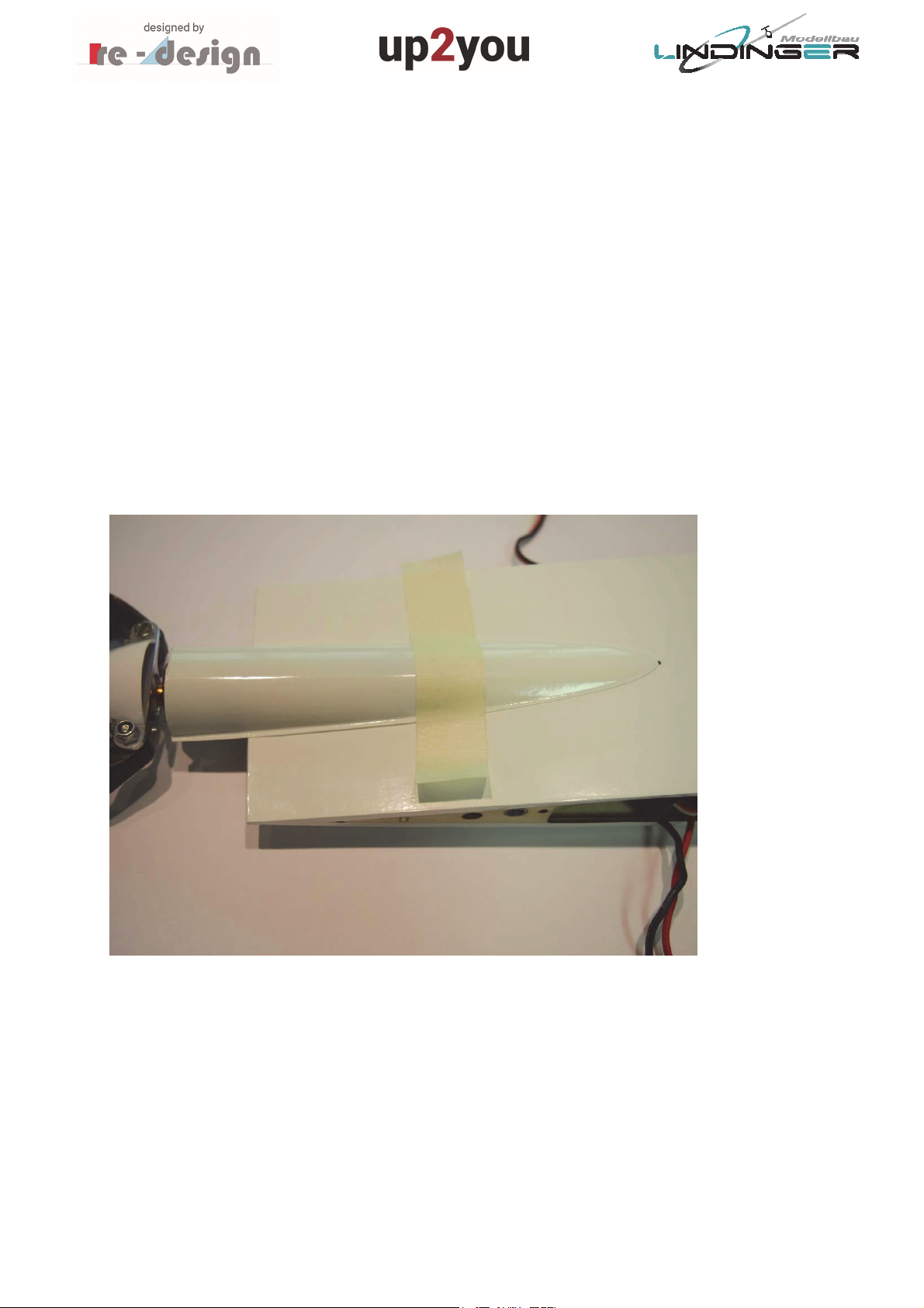
Then, the battery and the receiver can be installed for test purposes.
The battery for the pure glider version is placed in the front part of left wing. The dimension
should not be larger than:
50 x 45 x 12 mm (high x width x depth)
The capacity of the battery can be low – 500mAh should be enough for an afternoon flying
event.
The receiver is placed in the aft part of the left wing. There should be enough space, so its
size is relatively uncritical, refer to figure 13.
The servo of the left wing can be connected directly in the receiver. The connector of the
right-wing servo must be connected before the wing is assembled together.
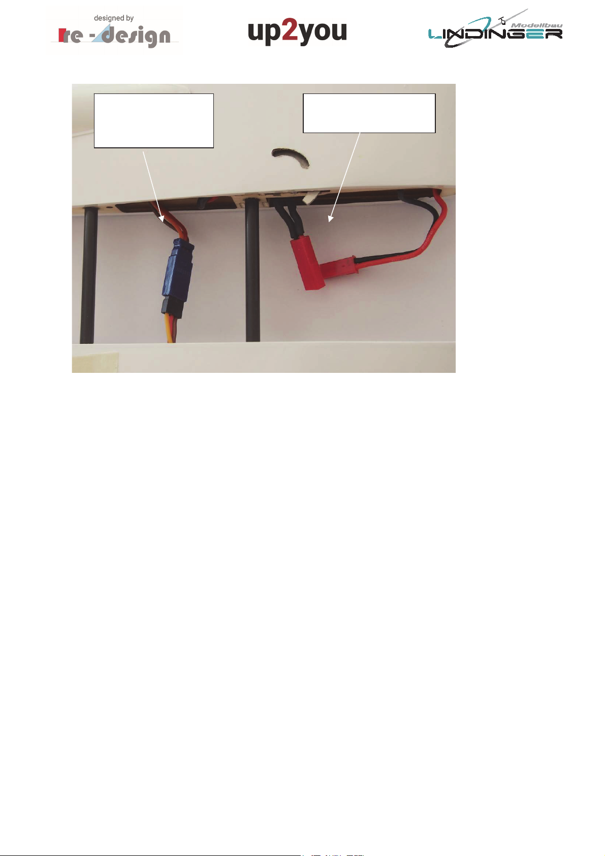
As shown in figure 13, there is a small switch connected (glued) to the battery which opens
and closes just the power line (red cable) from the battery to the receiver. The ground cable
remains closed.
In order not to disconnect the battery cable from the receiver for charging purposes, there
should be an additional cable soldered on the battery which could be used directly for
charging.
Figure 13 shows the proposed details which have been describes above. It is understood as a
proposal only and you may use your own ideas to connect battery, on/off-switch and
receiver.
After installing everything correctly, you can use some foam material in order to fix the
battery and the receiver.
With the installation method described above, it is only needed to connect the right-wing
servo to the receiver and switch the receiver on.
Pay attention during sliding the wings together that there is no cable jammed between the
both wings. They may be damaged when you arrest the hook.
12

Receiver
Servo cable from
the receiver-side
wing
Battery cable to
receiver (via
Switch)
Battery
charging cable
Optionally: Extension cable to right
wing servo (easier to connect to
receiver)
Figure 13, Installation of RC components in the pure sailplane
Switch the RC transmitter on and choose the correct modus. The functions “up-down” and
“roll” must be mixed. Such a mixing function is usually included in the RC transmitter (“deltamix”).
For a first functional test, the servos should be mounted in the wings. Check the if the servo
levers are in the neutral position as it is shown in figure 8. If this is not the case, adjust the
levers in a first step mechanically by disassemble it from the servo and adjust re-assemble it
on the correct position. Minor deviations from neutral position can be corrected
electronically with the corresponding function of the RC transmitter.
Check in the next step if the servo movement is correct with respect to the movement of the
stick of the RC transmitter.
13

Use the table below and carry out the 4 steps by visiting the servo movement whilst
commanding by the stick.
Test Steps Command of Stick Check of right-wing
servo
1. Step Pull Servo lever must
move in flight
direction
2. Step Push Servo lever must
move in opposite
flight direction
3. Step Stick to right side
(roll command right)
4. Step Stick to left side
(roll command left)
Note that the check above is valid only for the installation of the servos as proposed in this
manual, i.e. actuation of the elevons on the upper surface of the wing.
If you have enough experience with RC-models, you can skip the test steps above. As a
summary: By pulling the stick, both elevons must be moved up and vice versa. This is
identical with the movement of the stabilizer control on a model with fuselage and stabilizer.
By moving the stick to the right side, the right wing elevon must be move to down and the
left one up. Vice versa for a left command. This is identical for the ailerons of a RC-model.
This closes the Installation of the RC. The correct adjustment of the elevons as well as the
preparation of the linkage from the servo lever to the control horn of the elevons is
describes in chapter Fehler! Verweisquelle konnte nicht gefunden werden..
Servo lever must
move in flight
direction
Servo lever must
move in opposite
flight direction
Check of left-wing
servo
Servo lever must
move in flight
direction
Servo lever must
move in opposite
flight direction
Servo lever must
move in opposite
flight direction
Servo lever must
move in flight
direction
14

5. Installation of Motorization Parts in the Electro-Section
The up2ou-ARF is not intended to be a motorized speed model. The motorization proposal
below is intended to power it in a way to reach anytime the thermals from plain regions.
Motor: SCHNURRZ 1350 K/V # 9702265
Controller: RO-CONTROL 20A # 9744751
Batterie: RO-POWER 850 mAh/11,1 V 3S 9749045
Airscrew: AERONAUT CAM Carbon 8x4 # 57746
Spinner: CN-SPINNER COOL 30/2,0 mm # 72728
You may use different components, but you have eventually to change the bores in the
motor bulkhead.
The battery should not be larger than:
60 x 30 x 17 mm (high x width x depth)
A capacity of 850 mAh with a 3S Lipo is sufficient for several trials of searches for thermals.
The battery itself is also very quick to change or re-charged.
Screw the motor as shown in figure 14 on the motor bulkhead. Refer to figure 15 for the
positions of the controller and the battery. The motor cables will be guided through the hole
in upper cover – the shrink film must be cut out.
The cable from the controller to the receiver must be guided to the left wing. The power
cable from the controller to the battery must be guided underneath the front connector,
otherwise it would be jammed between the electro-section and the right wing.
If you fly predominant with the electro-section, you may remain it locked on the left wing for
transport.
To connect the right-wing servo cable to the receiver, an extension cable is needed which is
guided through the electro-section underneath the controller.
15

Figure 14, Fixation of the motor
Figure 15, Overview of installation of the motorization components
16
Before the motor covers will be glued on, a functional check should be done in order to
ensure that the motors shaft turns in the correct direction.
The airscrew must be operating in a push mode. This means that the blast of the airscrew
can be felt behind it when the motor is switched on.
You should fixate the model well on the table for this functional check and ensure that the
airscrew can be move without interfering with other parts or the table.
Caution: The moving airscrew can cause more or less heavy injuries. Fixate the model well
on the table before switching the motor on.
After the functional check has been successfully accomplished, glue the lower and upper
motor cover on. An edge of approx. 3mm which has been considered for cutting out the
cover is good surface for gluing, refer to figure 16.
Figure 16, Fixation (gluing) of the motor cover
With this step, the installation of the motorization parts is finish.
To get the model ready to fly, the right-wing servo must be connected to the enlargement
cable and the battery with the controller, refer to figure 17.
17
Servo cable and
enlargement cable
to receiver
Figure 17, Get ready for electro flying
Battery and controller
Power cable
18

6. Adjustment of Center of Gravity (CG) and Elevons
The correct adjustment of the CG of a tailless wing must be more precise carried out than at
a normal model with stabilizer. Also, the adjustment of the elevons muss be similar precise
and it must fit to the CG.
The following adjustment is proposed for the first flights in order to learn the behavior of the
model. With this adjustment, the model is very uncritical with respect to stall behavior.
Later, when you acquainted with the model, the CG can be moved more backward in order
to gain more performance. This adjustment is described in a second step.
Generally, the CG adjustments are given for the pure sailplane. They will be checked
afterwards on the electro-glider and usually there are no corrections necessary.
Please note, that the given dimension for the adjustment of the CG refers to the nose of the
pure glider version. If the electro-section is installed, the designation of the CG is referred to
the most forward point of the separation section between the wing(s) and the electrosection.
The safe location of the CG for the first flights (flying-in) is 160 mm.
Mark this point for the adjustment procedure as it is shown in figure 18.
At this marking the two plywood stripes as they are shown in figure 19 will be fixated with
tape. Drill a hole in each of the stripes and pull a cord through them. A knot behind each of
the stripes ensure that the cord is fixated between the two stripes.
Note that the cord should be strong enough to carry the model.
Tape the stripes as shown in figure 22 directly over the markings and start with the
adjustment procedure.
There will be not more than 50 g of lead needed in order to achieve the correct adjustment.
Use stripes of lead and fixate them in the first step with some tape on the nose, refer to
figure 20.
After you have achieved the correct CG adjustment glue the lead stripes in the very front
region of both wings, refer to figure 21.
The correct location of the CG is achieved when the nose swings slightly downward as it is
shown in figure 22.
Check again after gluing in the lead stripes if this is still the case.
19

Figure 18, Marking of the CG location
Figure 19, Plywood stripes and cord as a tool for CG adjustment
20

Figure 20, Stripes of lead preliminary adjusted during CG adjustment procedure
Fixation of lead
with little glue only
Figure 21, Gluing in of the lead stripes in the front region of the wings. Use little glue only in
order to be able to remove some lead for better performance adjustment
21

Figure 22, Check if the location of the CG is correct
Now you should check if the CG with the installed electro-section remains at the correct
location. As explained, the markings (on the wings) are identical regardless if the CG is
adjusted for the pure glider or for the electro-glider.
If you need some more lead in order to swing the nose of the electro-glider slightly
downwards, you can glue some lead in the nose of the electro-section. If the nose swings to
far downward, meaning that the CG is too far in a forward position, the only opportunity to
correct this, is to use a smaller and therefore lighter battery.
After the correct adjustment of the CG, the elevons should be adjusted:
Before doing so, the hinges of the elevons must be glued in and a linkage must be made.
Mark, as shown in figure 23, the location of the control horn on the elevon and cut out the
fit with a depth of approx. 5mm, refer to figure 24. Then glue the control horn in with epoxy.
Pay attention that the maximum deflection of the elevons reach approx. +-20° and that
there is enough clearance between the elevons and the wings to reach this maximum
deflection.
Also, pay attention that the gap between the outer side of the elevons and the winglets is in
the range of 1 – 2mm and that there is no interference between the winglets and the
elevons when moving them over the full deflection range.
Then, the hinges are glued in the elevons and the wings and the preparation of the linkage
as shown in figure 25 starts. The version of the linkage in figure 25 shows a soldered one.
22

Due to the fact that the elevon forces are not very high, the linkage could glue together as
well.
The correct adjustment of the elevons regarding the CG location of 160mm is 5mm upward,
measured on its inner side, refer to figure 26.
Figure 23, Marking of the location of the control horn
Figure 24, Cut out of the elevon fit
23

Figure 25, Completed linkage of elevon
Approx. 5 mm for
a CG location of
160 mm
Figure 26, Adjustment of elevons
As remarked earlier, the location of the CG can be moved more aft in order to gain more
performance from the model.
24

After successfully have flown in, you may re-adjust the CG accordingly to the table below.
Two steps are of performance increased CG locations are shown. Note that the most aft CG
location should be not more than 170mm. This location must be precise adjusted.
The corresponding elevon adjustments are also shown in the table:
CG location [mm] Elevon adjustment [mm]
Flying-in 160 5
1. Step of performance increase 165 3 - 4
2. Step of performance increase 170 2 - 3
If the model is trimmed and therefore balanced well, it is not a problem to launch it by
oneself, but ask a colleague to launch the model after you have re-adjusted the CG/elevons
in order to be able to react very quick if there are some trim actions necessary.
Note also the hints in chapter 7.
25
7. Flying
Once everything is correctly installed and adjusted, the first flight can be done.
In order to have a better grip of the model you may glue “grip increaser” made from two
pieces of sand paper (grain size 80) on it.
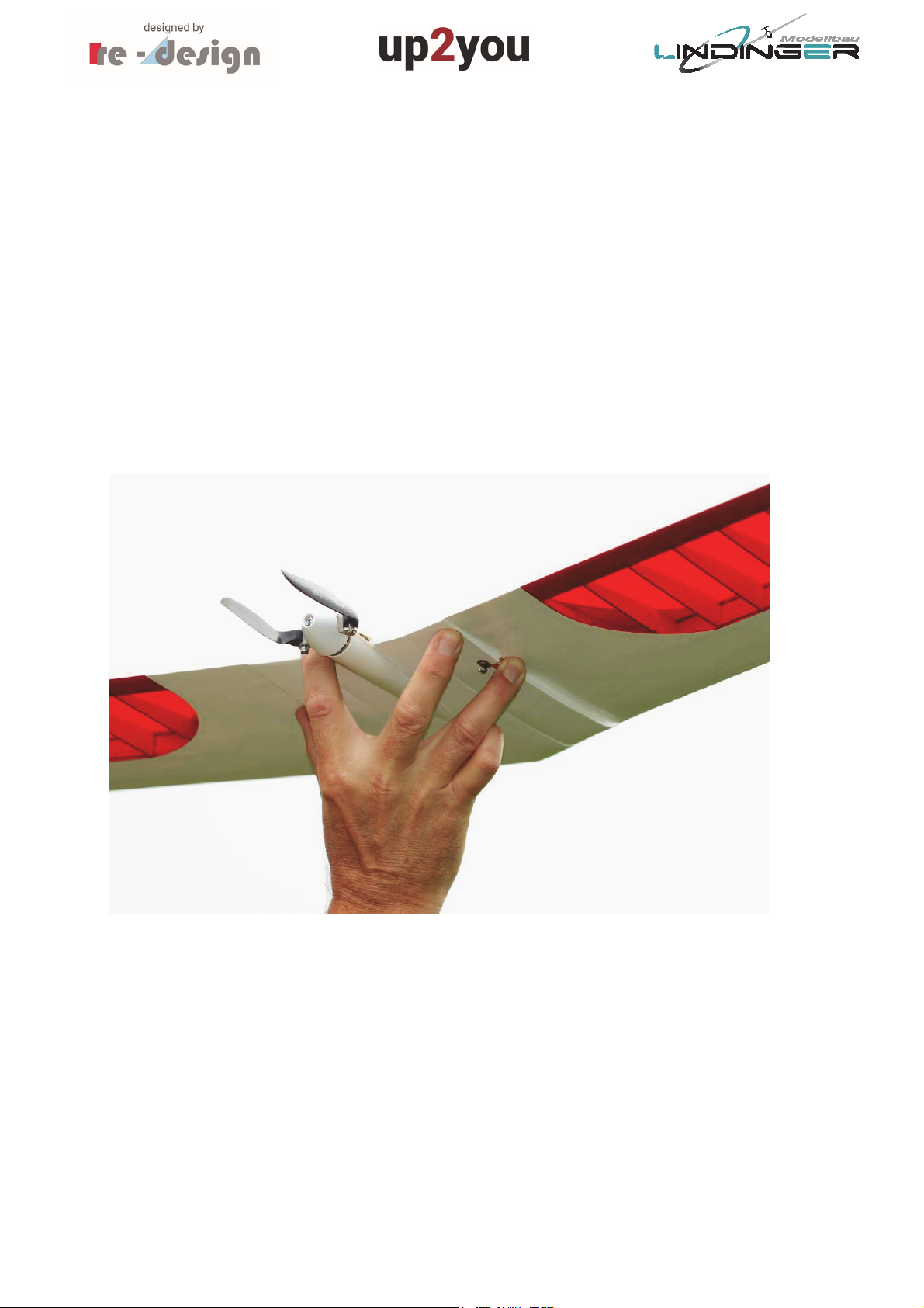
The best method to hold the model for launching it is, to place the trigger finger on its
trailing edge and grip it with the thumb and the middle finger/ring finger as it is shown in
figure 27.
Mark the location of your fingers on the model or ask someone to do so.
Then detach the shrink film on these two places and glue the grip increaser on, refer to
figure 29. Note that grip increaser should run over the edge, refer to figure 30.
Figure 27, Holding the model for launch
26
Figure 28, Shrink film detached on two points
Figure 29, Grip increaser glued on the model
27

Figure 30, Grip increaser
The first launch is carried out preferably with the pure glider in the plain or at a slope. Ask a
colleague to launch it – you can react better if there are trim actions needed.
After the model has been trimmed, you can launch it without problems alone.
The same applies for the first launch with the electro-section.
Note that the motor shall be switched on after the model has left the hand only. If you
switch on the motor earlier, it is very likely that the launch hand will be injured.
Under full motor performance, the model will be move slightly upward and to the right side.
Please note that it will move very quick out of the visibility range – the flight attitude of a
tailless wing is more difficult to identify than that for a normal model. Therefore, reduce the
power of the motor early enough. The purpose of the motor is to use it for short duration
only in order to find the next thermal.
You should have collected some experience with the model before doing low level show
events with full motor power.
A specialty of the model is the bungee launch. It’s fun the try to catch the thermals in the
plain and compete with a colleague for the longest flights.
28
For this launch method two hooks must be placed on the model in order to hook the forkshape end of the bungee in. These hooks can be made from pieces of steel wires or you may
use finished hooks for example from textiles.
As shown in figure 30, glue the hooks in a distance of 160mm from the nose.
Figure 31, Hooks for bungee launch
29
Figure 32, Hook detail
To launch the model with the bungee, hold it as shown in figure 33 with the thumb and the
pointer finger at the trailing edge. Trim it a little bit “nose up” and then clear it.
You can do nothing wrong with this launch method beside not enough tension on the
bungee.
The length of the rubber and the cord of the bungee is uncritical – it depends on the flying
site and your preferences. The length of the piece of the fork end cord to hook in the two
hooks is also uncritical – it should be approx. of 40cm length.
30
Figure 33, Ready for bungee launch
8. For technical interested Modelers
In order to explain how tailless wings are able to achieve a stable flight, one must have
understood the fundamentals of normal aircrafts with a horizontal stabilizer. Or more
precise, one must have understood the function of the stabilizer.
For this, the following explanation: In order to achieve a stable flight, the location of the CG
must be in determined relationship along the flight direction with respect to the Lift. The
location of the total wing lift can be concentrated in one point acting on the aircraft. This
point is usually known as “neutral point”.
One of some other main preconditions for a stable flight is, that the CG is in front of the
neutral point with respect to the flight direction, refer to figure 34.
31

Lift
Center of Gravitiy
Neutral Point
Figure 34, Location of CG and neutral point for stable flight at an airplane with horizontal
stabilizer
Due to the physic fact that bodies move around the CG whilst free movement, figure 34
shows clear that the lift tries to turn the nose “around the CG” upward. To react this, the
stabilizer is needed – it supplies an amount of torque which equalizes exactly the torque
which is applied by the lift.
The more forward the CG is moved, the higher must the counteracting torque of the
stabilizer.
Every modeler who has flown a model with stabilizer knows this: Moving the CG more
forward means that the elevator must be “pulled” more, or the angle of attach of the
stabilizer must be installed with a higher differential angle with respect to the wing. The
stabilizer has to supply negative lift and this costs performance.
For the sake of completeness, it must be mentioned that the torque which comes from the
lift is not the only torque which tries to pitch down the nose of the aircraft.
Also, the airfoil of the wing exerts such a torque. This torque however can be changed by
special shapes of the airfoil in order to keep this torque as low as possible or even change
the direction – some more explanations will follow.
In order to achieve a high performance of the aircraft, the shape of an airfoil of an aircraft
with stabilizer supplies a nose pitch down torque.
It is clear that the stabilizer must react this torque also, refer to figure 35.
32

N
Quarter
Q
Lift
Center of Gravitiy
eutral Point
Figure 35, Pitch down torque of the airfoil
Bevor the explanation how the equalization of the lift pitch down torque works on a tailless
wing, i.e. an aircraft without any horizontal stabilizer is given, just a short explanation for the
two principal tailless wing types.
One distinguishes between:
Tailless wings with swept back wings
Tailless wings without sweep, usually known as “flying planks”
The sweep is usually referred to line along the wing span which connects all 25% chord
points. For the simple shape of a trapezoidal wing this looks like as shown in figure 36.
Flight mechanic engineers use the expression “quarter-chord-line” for this line. It plays an
important role in aerodynamics and flight mechanics.
Sweep angle
uarter-chord-line
-chord-line
Figure 36, Explanation of quarter-chord-line and sweep
The sweep of the up2you-ARF is 17°. This value has been optimized by many calculations has
been proved as an optimum with respect to some flight mechanic aspects.
It is interested to know that one of the biggest flying seeds, the zanionia tree seed which
grows on Indonesia exhibits also a sweep back angle of approximately 15° - 25°. Obviously,
the process of evolution leads to this sweep angle.
33

A look on the map makes it clear why the tree is interested in a high-performance seed:
Indonesia is sample of many isles. In order to distribute the tree all over the isles, the seeds
must be able to climb in thermals and glide long distances over the sea. Figure 37 shows a
zanonia seed or better expressed a seed which is perfectly integrated in a tailless wing.
Figure 37, Zanonia Seed as tailless wing
Back to model airplanes: A flying plank is a tailless wing without no or a very low sweep of
the quarter-chord-line.
How is the counter reacting torque of the lift is achieved for a flying plank?
The used airfoil must have a “s-shape”. Such an airfoil generates a nose pitch up torque. The
torque symbol (arrow) in figure 35 is points upward for such an airfoil.
S-shape airfoils exhibit a crucial disadvantage: They supply, compared to “normal” airfoils,
less lift. The deletion of the horizontal stabilizer is paid with significant less performance of
the model.
This is the main reason why flying planks are well suited for fast flying on slopes but why
they are not very useful for climbing in weak thermals.
How is the counter reacting torque of a swept back wing is achieved?
This is accomplished by using a twist of the wing along its span. The angle of attack of the
wing decreases from the wing root to the wing tip. Figure 38 shows this schematically.
34

Wing root
Wing tip
Figure 38, Wing twist for a swept back tailless wing
The wing twist is designed in the simplest case continuously linearly from the wing root to
the wing tip. But other, more complex twist distributions could be used in order to achieve a
better fine-tuned aerodynamic and flight mechanic.
The Horten Brothers in Germany used in the 1930th and 1940th a special distribution of the
wing twist which made their tailless wing sailplanes easy to fly with respect to stall behavior.
By looking on figure 38 it becomes clear that the wing twist is in principle a horizontal
stabilizer which is installed with a suitable differential angle of attack with respect to the
wing.
Similar as for an elevator on a stabilizer, the elevons can be adjusted upward in order to
increase the counter acting torque of the lift. The torque is then a combination which results
from sweep/twist and upward adjusted elevons. The design of the up2you-ARF follows this.
As a concluding remark: Swept back tailless wing design gives the designer more freedom in
the design and selection of the airfoil. The airfoil must be not of a s-shape as it has to be
used for a flying plank. Therefore, swept back wings usually have a better performance,
especially if they used for sailplanes.
35

9. General information:
The model is designed for the components specified by us. Unless otherwise stated,
servos and other electronic components are designed for standard supply voltage.
Recommended cell count for Lipo batteries also refers to standard Lipos voltage of
3.7V per cell. If you use other servos, a different motor and controller, batteries, or
propellers, please make sure they fit first. In the event of deviations, corrections and
adjustments must be made by yourself.
Before starting construction, always put the servos into neutral. To do this, switch on
the remote control and move the joysticks and trim buttons (save the one for the
throttle) to the middle position. Connect the servos to the corresponding outputs of
the receiver and supply them with a suitable power source. Please observe the
connection diagram and the operating instructions of the remote control system
manufacturer.
Do not leave your model in the blazing sun or in your vehicle for long periods of time.
Too high temperatures can lead to deformation/distortion of plastic parts or
blistering of covering foils.
Before the first flight, check the wing symmetry, tail unit and fuselage. All parts of the
model should have the same spacing from the left and right wing or tail plane to the
centre of the fuselage or the same angle.
If necessary, rebalance the propellers if vibrations are noticeable when the motor is
running up.
Bubble formation in the covering foils normal to a certain extent due to temperature
and humidity differences and can be easily eliminated with a foil iron or hairdryer.
For models in shell construction ("full GFRP/CFRP"), burrs may occur at the seams
due to the production process. Carefully remove them with fine sandpaper or a file.
General safety information:
Be sure to read the safety instructions carefully before operating your model.
Always follow the procedures and settings recommended in the instructions.
If you are using remote-controlled model aircraft, helicopters, cars or ships for the
first time, we recommend that you ask an experienced model pilot for help.
Remote-controlled models are not toys in the usual sense and may only be used and
operated by young people under 14 years of age under the supervision of adults.
Their construction and operation requires technical understanding, careful
craftsmanship and safety-conscious behaviour.
Mistakes or negligence during construction, flying or driving can result in
considerable damage to property or personal injury.
Since the manufacturer and seller have no influence on the proper
construction/assembly and operation of the models, these risks are expressly pointed
out and any liability is excluded.
Propellers on aircraft and all moving parts in general pose a constant risk of injury.
Avoid touching such parts at all costs.
36

Note that motors and controllers can reach high temperatures during operation.
Avoid touching such parts at all costs.
Never stay in the danger area of rotating parts with electric motors with connected
drive battery.
Overcharging or incorrect charging can cause the batteries to explode. Make sure the
polarity is correct.
Protect your equipment and Models from dust, dirt and moisture. Do not expose the
equipment to excessive heat, cold or vibration.
Use only recommended chargers and charge your batteries only up to the specified
charging time. Always check your equipment for damage and replace defects with
original spare parts.
Do not use equipment that has been damaged or got wet due to a fall, even if it is dry
again! Either have it checked by your specialist dealer or in the Service or have it
replaced. Hidden faults can occur due to wetness or a crash, which lead to a
functional failure after a short operating time.
Only the components and accessories recommended by us may be used.
Do not make any changes to the remote control which are not described in these
instructions.
Safety instructions for controllers:
Observe the technical data of the controller.
Observe the polarity of all connection cables.
Avoid short circuits at all costs.
Install or package the regulator so that it cannot come into contact with grease, oil or
water.
Ensure adequate air circulation.
Never reach into the turning circle of the propeller during start-up Risk of injury
Important information:
The receiver system is powered by the built-in BEC system of the controller.
For commissioning, always move the throttle stick to the "Motor off" position and switch on
the transmitter. Only then connect the battery. To switch off always disconnect the
connection battery motor controller, first
then turn off the transmitter. During the functional test, move the servos of the rudders to
neutral position with the remote control (stick and trimming lever on the transmitter to the
middle position). Please make sure to leave the throttle stick in the lowest position so that
the engine does not start. For all work on
to the parts of the remote control, motor or controller, follow the instructions supplied with
the units. Also read the instructions of the battery and the charger carefully before
commissioning.
Check the engine mounting bolts in the fuselage regularly for tightness.
37

Safety note for model operation:
Attention, danger of injury!
Always keep a safe distance from your model aircraft.
Never fly over spectators, other pilots or yourself.
Always perform flight figures in a direction away from the pilot or spectators.
Never endanger people or animals.
Never fly near power lines or residential areas.
Do not operate your model near locks or public shipping.
Do not operate your model on public roads, motorways, paths and squares, etc., but
only in approved locations.
Do not operate the model in thunderstorms.
Before each flight, check your remote control system for sufficient function and
range.
After flying, remove all batteries from the model.
Safety instructions for rechargeable batteries:
Do not immerse the battery in water or other liquids.
Do not heat, throw into fire or microwave.
Do not short-circuit or charge with reversed polarity
Do not expose, deform or throw the battery to pressure
Do not solder directly on the battery
Do not change or open the battery
Only charge the battery with suitable chargers, never connect it directly to a power
supply unit.
Never charge or discharge the battery or charger on a flammable surface.
Never leave the battery unattended during charging or discharging processes.
Never charge or discharge the battery in direct sunlight or near heaters or fire.
Do not use the battery in places subject to high static discharge.
All this can cause the battery to be damaged, explode or even catch fire!
Keep the battery away from children
Do not associate leaked electrolyte with fire, as it is highly flammable and may ignite.
The electrolyte liquid should not get into the eyes, if it does, rinse immediately with
plenty of clear water and then see a doctor.
The electrolyte liquid can also escape from clothes and other objects with a lot of
water. or washed off
Observe the safety instructions of the battery manufacturer and the charger
manufacturer.
38

Disclaimer conformity, warranty, disposal, insurance:
Modellbau Lindinger GmbH hereby declares that this device complies with the essential
requirements and other relevant regulations of the corresponding CE directives.
Warranty:
Our articles are equipped with the legally required 24 months warranty. Should you wish to
assert a justified warranty claim, always contact your dealer, who is responsible for the
warranty and the processing. During this time, any functional defects that may occur, as well
as manufacturing or other problems, will be rectified.
Material defects corrected by us free of charge. Further claims, e.g. for consequential
damages, are excluded.
The transport to us must be free, the return transport to you is also free. Freight collect
shipments cannot be accepted. We cannot accept liability for transport damage and loss of
your consignment. We recommend appropriate insurance.
To process your warranty claims, the following requirements must be met:
Attach the proof of purchase (receipt) to your shipment.
The units have been operated in accordance with the operating instructions.
Only recommended power sources and accessories have been used.
There is no moisture damage, external interference, reverse polarity, overloading or
mechanical damage.
Attach relevant information for finding the fault or defect.
Insurance:
Ground-based models are usually covered by personal liability insurance. Additional
insurance or extension is required for aircraft models. Check your insurance policy (private
liability) and take out suitable insurance if necessary.
Disclaimer:
Modellbau Lindinger GmbH cannot monitor compliance with the assembly and operating
instructions or the conditions and methods for installation, operation, use and maintenance
of the model components.Therefore, we accept no liability for losses, damage or costs
arising from or in any way connected with incorrect use and operation.To the extent
permitted by law, the obligation to pay damages, irrespective of the legal grounds, shall be
limited directly to the invoice value of the claims arising from the event causing the damage.
39

Flying in, flight instructions:
Before the first flight, observe the instructions in the "Safety Instructions" section.
To fly in the model, you should choose a day with as little wind as possible
A large, flat meadow without obstacles (trees, fences power lines etc.) is suitable for
the first flights.
Carry out another functional test of the drive and remote control.
After assembling the model on the airfield, check once again that all model
components such as wing, tail units, wing mounts, engine, linkage, etc. are firmly
seated.
For the hand start a helper should be present, who can transport the model with not
too little thrust into the air.
The start usually takes place against the wind
Do not stall the model near the ground
Do not initiate tight bends in the immediate vicinity of the ground.
Check the reactions of the model to the rudder deflections. If necessary, the rashes
after landing
to increase or decrease the size accordingly.
The minimum flight speed must be at an adequate safety altitude.
Initiate the landing with sufficient speed
Modellbau Lindinger GmbH
Industriestraße 10, 4565 Inzersdorf im Kremstal
Austria
Phone: +43(0)7582/813130, Mail: office@lindinger.at
UID Nr.: ATU69266037
Errors, misprints and technical changes reserved.
Copyright 2018
Modellbau Lindinger 2018
Copy and reprint only with our permission.
Service-Adresse
Contact your Dealer or:
Modellbau Lindinger GmbH, Industriestraße 10, 4565 Inzersdorf im Kremstal
Mail: service@lindinger.at, Phone: +43(0)7582-81313-0
40
 Loading...