


RED DSMC MEDIA
OPERATION GUIDE
RED MINI-MAG SYSTEM | REDMAG 1.8" SSD SYSTEM
RED.COM

RED DSMC MEDIA OPERATION GUIDE
TABLE OF CONTENTS
Disclaimer 3
Copyright Notice 3
Trademark Disclaimer 3
Compliance Statements 3
Safety Instructions 5
Chapter 1: DSMC Media Overview 6
RED MINI-MAG System 6
REDMAG 1.8” SSD System 7
Mixing Carbon Fiber and Aluminum Components 8
Additional Resources 8
Chapter 2: RED MINI-MAG System 9
RED MINI-MAG 9
RED MINI-MAG Modules 10
RED STATION RED MINI-MAG 12
Chapter 3: REDMAG 1.8” SSD System 15
REDMAG 1.8” SSD 15
SSD Modules 16
RED STATIONS 22
Chapter 4: Install Media Modules 32
Install Side Media Modules 32
Install the REAR SSD MODULE 35
Eject Media from Camera (Unmount) 35
Chapter 5: Format Media 36
Overview 36
Format (Erase) Media In-Camera 36
Format (Erase) Media Via Computer 38
Clip Naming Conventions 40
Metadata 40
Media Capacity Remaining Status 41
Chapter 6: Offload Media 42
Connect RED MINI-MAGS to your Computer 42
Connect REDMAG 1.8” SSDS to Your Computer 43
Offload Data From Media to Your Computer 45
RED Watchdog 45
Chapter 7: Upgrade SSD Firmware 46
Verify Current SSD Firmware 46
Upgrade REDMAG 1.8” SSD (512GB) Firmware 47
Chapter 8: Troubleshoot Media 48
In-Camera Errors 48
Media Does Not Mount to Camera 48
Media Does Not Mount to Computer 49
LED Does Not Illuminate on RED Station 49
Cannot Format SSD on Computer 49
Identify SSD Type In-Camera 50
Appendix A: Technical Specifications 51
RED MINI-MAG 51
Carbon Fiber RED MINI-MAG Side SSD Module 51
RED MINI-MAG SIDE SSD MODULE 52
RED STATION RED MINI-MAG 52
REDMAG 1.8” SSD 53
DSMC 1.8” SSD SIDE MODULE 53
RED STATION REDMAG 1.8” 54
RED STATION REDMAG 2.5” 55
RED STATION BASE 55
Appendix B: REDCODE Options 56
RED MINI-MAG REDCODE Options 56
REDMAG 1.8” SSD REDCODE Options 61
SCARLET-X DRAGON REDCODE Options 77
SCARLET MYSTERIUM-X REDCODE Options 78
COPYRIGHT © 2014 RED.COM, INC
955-0047, REV-E | 2

RED DSMC MEDIA OPERATION GUIDE
DISCLAIMER
RED has made every effort to provide clear and accurate information
in these installation instructions, which are provided solely for the
user’s information. While thought to be accurate, the information in
this document is provided strictly “as is” and RED will not be held
responsible for issues arising from typographical errors or user’s
interpretation of the language used herein that is different from that
intended by RED. All safety and general information is subject to
change as a result of changes in local, federal or other applicable
laws.
RED reserves the right to revise this document and make changes
from time to time in the content hereof without obligation to notify
any person of such revisions or changes. In no event shall RED, its
employees or authorized agents be liable to you for any damages
or losses, direct or indirect, arising from the use of any technical or
operational information contained in this document.
For comments or questions about content in this Operation Guide,
please send a detailed e-mail to OpsGuides@red.com.
COMPLIANCE STATEMENTS
INDUSTRIAL CANADA EMISSION COMPLIANCE STATEMENTS
This Class B digital apparatus complies with Canadian ICES-003.
Cet appareil numérique de la classe B est conforme à la norme
NMB-003 du Canada.
FEDERAL COMMUNICATIONS COMMISSION (FCC) STATEMENTS
This equipment has been tested and found to
comply with the limits for a Class B digital device, pursuant to part 15 of the FCC Rules.
These limits are designed to provide reasonable protection against harmful interference
in a residential installation. This equipment
generates, uses and can radiate radio fre-
quency energy and, if not installed and used
in accordance with the instructions, may cause harmful interference
to radio communications. However, there is no guarantee that interference will not occur in a particular installation. If this equipment
does cause harmful interference to radio or television reception,
which can be determined by turning the equipment off and on, the
user is encouraged to try to correct the interference by one or more
of the following measures:
Reorient or relocate the receiving antenna.
Increase the separation between the equipment and receiver.
Connect the equipment into an outlet on a circuit different from
that to which the receiver is connected.
Consult the dealer or an experienced radio/TV technician for
help.
NOTE: This device complies with Part 15 of the FCC Rules.
Operations subjected to the following two conditions (1) this device
may not cause harmful interference, and (2) this device must accept
any interference received, including that may cause undesirable interference.
CAUTION: If the device is changed or modified
without permission from RED, the user may
void his or her authority to operate the equipment.
COPYRIGHT NOTICE
COPYRIGHT© 2014 RED.COM, INC.
All trademarks, trade names, logos, icons, images, written material,
code, and product names used in association with the accompanying product are the copyrights, trademarks or other intellectual
property owned and controlled exclusively by RED.COM, INC.
TRADEMARK DISCLAIMER
All other company, brand and product names are trademarks or registered trademarks of their respective holders. RED has no affiliation
to, is not associated or sponsored with, and has no express rights
in third-party trademarks. SEARAY is a trademark of Samtec, Inc.
AUSTRALIA AND NEW ZEALAND STATEMENTS
This device has been tested and found to comply with the limits for
a Class B digital device, pursuant to EN 55022:2006.
JAPAN STATEMENTS
This is a Class B product based on the
standard of the Voluntary Control Council
for Interference (VCCI) for information technology equipment. If this equipment is used
near a radio or television receiver in a domestic environment, it may cause radio interference. Install and use the equipment
according to the instruction manual.
EUROPEAN UNION COMPLIANCE STATEMENTS
RED declares that the
equipment described in this
document complies with the
requirements of the European Council EMC Directive
2004/108/EC, Low Voltage
Directive 2006/95/EC, RoHS
Directive 2002/95/EC, and the WEEE Directive 2002/96/EC.
This declaration is based on compliance of the product to the fol-
lowing standards.
EN 55022, Information Technology Equipment - Radio Distur-
bance Characteristics
EN 55024, Information Technology Equipment - Immunity
Characteristics
EN 61000-3-2, Limits for harmonic current emissions
EN 61000-3-3, Limits for harmonic current emissions
EN 60950-1, Information Technology Equipment – Safety
COPYRIGHT © 2014 RED.COM, INC 955-0047, REV-E | 3

RED DSMC MEDIA OPERATION GUIDE
INFORMATION
Products with the CE marking comply with the EMC Directive
(2004/108/EC) and the Low Voltage Directive (2006/95/EC) issued
by the Commission of the European Community. Compliance with
these directives implies conformity to the following European Product Family Standards.
EN 55022 (CISPR 22) – Electromagnetic Interference
EN 55024-1 (CISPR 24) – Electromagnetic Immunity
EN 61000-3-2 (IEC610000-3-2) – Power Line Harmonics
EN 61000-3-3 (IEC610000) – Power Line Flicker
EN 60065 (IEC60065) – Product Safety
NORWAY
This subsection does not apply for the geographical area within a
radius of 20 km from the centre of Ny-Ålesund
Dette gjelder ikke for det geografiske området innenfor en radius av
20 km fra sentrum av Ny-Ålesund
The Waste Electrical and Electronic Equipment (WEEE) mark applies only to countries
within the European Union (EU) and Norway.
This symbol on the product and accompanying documents means that used electrical
and electronic products should not be mixed
with general household waste. For proper
treatment, recovery and recycling, please
take this product to designated collection
points where it will be accepted free of
charge. Alternatively, in some countries you
may be able to return your products to your
new product.
Disposing of this product correctly will help save valuable resources
and prevent any potential negative effects on human health and the
environment, which could otherwise arise from inappropriate waste
handling. Please contact your local authority for further details of
your nearest designated collection point. Penalties may be applicable for incorrect disposal of this waste, in accordance with you
national legislation.
For business users in the European Union, if you wish to discard
electrical and electronic equipment, please contact your dealer or
supplier for further information.
local retailer upon purchase of an equivalent
RESPONSIBLE PARTY:
RED Digital Cinema
34 Parker
Irvine, CA 92618
USA
COPYRIGHT © 2014 RED.COM, INC
955-0047, REV-E | 4

RED DSMC MEDIA OPERATION GUIDE
SAFETY INSTRUCTIONS
DO NOT use the media or media modules near water. Avoid
exposing your media or media modules to moisture. The units
are not waterproof, so contact with water could cause permanent damage to the units as well as electric shock and serious
injury to the user. DO NOT use the media or media modules in
the rain or under other conditions with high moisture without
appropriate protection, and immediately remove power source
if the media or media modules are exposed to moisture.
WARNING: To reduce the risk of fire or electric shock, do not expose the media or
media modules to rain or moisture.
If fluids or foreign objects get inside any of the media modules
or RED STATIONS, disconnect the power source immediately
and file a support ticket on support.red.com.
DO NOT expose your media or media modules to excessive
vibration or impact (shock). Be careful not to drop your media
or media modules. Internal mechanisms may be damaged by
severe shock. Mechanical alignment of elements may be affected by excessive vibration.
Avoid using the media or media modules in areas with high
humidity or dust.
DO NOT expose the media or media modules to strong elec-
tronic or magnetic fields.
Clean only using a dry cloth. When cleaning your media or
media modules, remember that it is not waterproof and moisture can damage electronic circuitry. DO NOT rinse or immerse
any element of the media or media modules, keep them dry at
all times. DO NOT use soaps, detergents, ammonia, alkaline
cleaners, and abrasive cleaning compounds or solvents. These
substances may damage coatings and electronic circuitry.
The RED STATIONS operate best in an air-conditioned environ-
ment.
DO NOT operate or store near any heat sources such as radia-
tors, heat registers, stoves, or any other apparatus that produce heat. Store in a protected, level and ventilated place.
Avoid exposure to temperature extremes, damp, severe vibration, strong magnetic fields, direct sunlight or local heat sources during storage. Recommended storage and usage temperatures for your media and media modules are:
‒ Operating range: 0°C to 40°C (32°F to 104°F)
‒ Storage range: -20°C to 50°C (-4°F to 122°F)
If there are any performance issues with your media or media
modules when operating within this temperature range, please
file a support ticket on support.red.com.
The REAR SSD MODULE, RED MINI-MAG SIDE SSD MODULE,
and DSMC 1.8" SSD SIDE MODULE are NOT HOT SWAPPABLE – meaning you cannot remove or install them while the
camera is powered on. Before installing or removing any of
these modules, you MUST power down the camera. Failure
to do so may result in damage to the module and / or camera
brain that will not be covered under warranty.
Protect all power cords from being pinched, walked on or
driven over by a vehicle. Replace any power cords suspected
of sustaining damage due to crushing or other forms physical
damage. Use media and media modules only when they are in
good operating condition.
Always use the original packaging or similarly structured pack-
aging for transportation.
USE AT YOUR OWN RISK. RED is not responsible for lost data,
corrupted data, or damaged SSDs while using any of the SSD
media modules or RED STATIONS.
CAUTION: Refer all service and repair to
qualified RED service personnel. To reduce
the risk of electric shock, and damage to
the camera or accessories, DO NOT attempt to perform any servicing other than
any procedures that are recommended in
the operating instructions.
COPYRIGHT © 2014 RED.COM, INC 955-0047, REV-E | 5

RED DSMC MEDIA OPERATION GUIDE
DSMC MEDIA
01
RED offers two (2) media systems for your RED Digital Still and Motion Camera (RED DSMC®):
RED MINI-MAGTM system
REDMAGTM 1.8" SSD system
OVERVIEW
RED MINI-MAG SYSTEM
This system centers around the RED MINI-MAG, which is the fastest, smallest, and most powerful media option
for your RED EPIC or SCARLET camera. RED MINI-MAGS use a faster read/write speed for capturing higher
frame rates and resolutions with less compression than previous DSMC media systems.
RED MINI-MAG
PACKAGE
RED MINI-MAG SYSTEM COMPONENTS
The RED MINI-MAG system includes the following items, available at red.com (this table does not include any
of the RED MINI-MAG collections or packages, which are made up of the items below):
ITEM PART NUMBER
RED MINI-MAGTM (512GB) 750-0053
RED MINI-MAGTM SIDE SSD MODULE 720-0021
Carbon Fiber RED MINI-MAG TM Side SSD Module
RED STATION® RED MINI-MAG
RED MINI-MAGTM CASE (4-PACK) 790-0404
RED MINI-MAGTM CASE (12-PACK) 790-0405
1. The Carbon Fiber RED MINI-MAG Side SSD Module is only available with a carbon fiber DSMC BRAIN.
COPYRIGHT © 2014 RED.COM, INC
TM
1
NA
750-0055
955-0047, REV-E | 6

RED DSMC MEDIA OPERATION GUIDE
REDMAG 1.8" SSD SYSTEM
This system centers around the REDMAG 1.8" SSD, which is a fast and reliable media option for your DSMC.
DSMC MEDIA PACK
REDMAG 1.8" SSD SYSTEM COMPONENTS
The REDMAG 1.8" SSD system includes the following items, available at red.com (this table does not include
any of the REDMAG 1.8" SSD collections or packages, which are made up of the items below):
ITEM PART NUMBER
REDMAGTM 1.8" SSD (48GB) 750-0044
REDMAGTM 1.8" SSD (64GB) 750-0025
REDMAGTM 1.8" SSD (128GB) 750-0021
REDMAGTM 1.8" SSD (240GB)
REDMAGTM 1.8" SSD (256GB) 750-0026
REDMAGTM 1.8" SSD (512GB)
RED DSMC® SIDE 1.8" SSD MODULE 720-0013
RED DSMC® SIDE 1.8" SSD MODULE (DRAGON)
RED DSMC® SIDE 1.8" SSD MODULE (CARBON FIBER DRAGON)
REAR SSD MODULE 720-0009
RED STATION® REDMAGTM 1.8" 750-0006
RED STATION® REDMAGTM 1.8" (MINI)–ESATA 750-0035
RED STATION® REDMAGTM 1.8" (MINI)–USB 3.0 750-0036
RED STATION® REDMAGTM 2.5" 750-0007
RED STATION® BASE 750-0004
REDMAGTM CASE (4-PACK) 790-0204
REDMAGTM CASE (12-PACK) 790-0144
1. The REDMAG 1.8" SSD (240GB) requires that your DSMC is on firmware v5.1.44 or later.
2. The REDMAG 1.8" SSD (512GB) is no longer available for purchase at red.com, but is still supported by RED.
3. The DSMC 1.8" SSD SIDE MODULE (DRAGON) is only available with a DSMC with a RED DRAGON sensor.
4. The DSMC 1.8" SSD SIDE MODULE (CARBON FIBER DRAGON) is only available with a carbon fiber DSMC BRAIN.
1
2
3
4
750-0061
750-0037
NA
NA
COPYRIGHT © 2014 RED.COM, INC 955-0047, REV-E | 7

RED DSMC MEDIA OPERATION GUIDE
MIXING CARBON FIBER AND ALUMINUM COMPONENTS
The structural mounting points for the carbon fiber media modules are optimized for the carbon fiber DSMC
BRAIN, whereas the structural mounting points for the standard aluminum side SSD modules are optimized for
use with the standard aluminum DSMC BRAIN.
Using a carbon fiber media module with an aluminum DSMC BRAIN or using an aluminum side SSD module with
a carbon fiber DSMC BRAIN may lead to an unstable connection between the BRAIN and the module, which
could affect data integrity.
WARNING: Damage to the DSMC BRAIN, side SSD module, or other components of the DSMC system caused
by mixing carbon fiber components with non-carbon-fiber components is not covered under warranty, and may
void the warranty for both the BRAIN and the side SSD module.
SUMMARY OF CARBON FIBER RESTRICTIONS
DO NOT attach any of the following side SSD modules to a carbon DSMC BRAIN:
RED MINI-MAG SIDE SSD MODULE
DSMC 1.8" SSD SIDE MODULE
DSMC 1.8" SSD SIDE MODULE (DRAGON)
DO NOT attach the following side SSD modules to a standard aluminum DSMC:
Carbon Fiber RED MINI-MAG Side SSD Module
DSMC 1.8" SSD SIDE MODULE (CARBON FIBER DRAGON)
ADDITIONAL RESOURCES
The following resources offer additional information about RED, the DSMC system, and the RED community:
RED.com: Check the official RED website for the latest information about RED products.
RED Learn Articles: RED offers in-depth technical articles about RED cameras, post-production, and digital
cinematography.
RED.com/downloads: Go to the RED Downloads page to download the latest firmware, operation guides,
and post-production software.
Support.red.com: Check the RED SUPPORT site for FAQs, or to file a support ticket.
Reduser.net: Discuss all things RED on the REDUSER third-party forum.
COPYRIGHT © 2014 RED.COM, INC
955-0047, REV-E | 8
RED DSMC MEDIA OPERATION GUIDE
RED MINI-MAG
02
SYSTEM
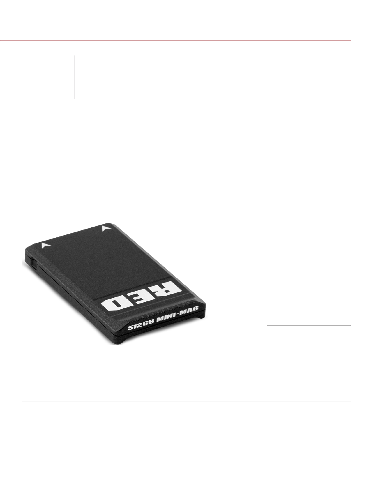
RED MINI-MAG
The RED MINI-MAG is the fastest, smallest, and most powerful media option for your RED EPIC® or SCARLET®
camera. RED MINI-MAGS use a faster read/write speed for capturing higher frame rates and resolutions with
less compression than previous DSMC media systems.
The RED MINI-MAG is available in the following storage capacity: 512GB.
NOTE: The RED MINI-MAG system requires that your DSMC is on firmware v5.1.34 or later. If your DSMC is
on an earlier version, you can use the RED MINI-MAG to upgrade to v5.1.34 or later. While you can use a
RED MINI-MAG to downgrade to DSMC firmware versions earlier than v5.1.34, the DSMC will not be fully functional with the RED MINI-MAG SIDE SSD MODULE installed. You will need to either switch to a
DSMC 1.8" SSD SIDE MODULE or upgrade to v5.1.34 or later.
RED MINI-MAG
RED MINI-MAG INCLUDED COMPONENTS
The item listed in the table below ships with the RED MINI-MAG.
ITEM PART NUMBER
RED MINI-MAG (512GB) 750-0053
COPYRIGHT © 2014 RED.COM, INC
955-0047, REV-E | 9

RED DSMC MEDIA OPERATION GUIDE
RED MINI-MAG MODULES
RED offers the following RED MINI-MAG modules:
RED MINI-MAG SIDE SSD MODULE: Mounts to any standard aluminum DSMC BRAIN.
Carbon Fiber RED MINI-MAG Side SSD Module: Mounts to any carbon fiber DSMC BRAIN, and is only available
with a carbon fiber DSMC BRAIN.
Each RED MINI-MAG module attaches to the DSMC so that you can mount a RED MINI-MAG to your camera.
Each RED MINI-MAG module has the same EVF/LCD LEMO connector, user keys, and REC button as the
DSMC 1.8" SSD SIDE MODULE.
WARNING: The RED MINI-MAG modules are NOT HOT SWAPPABLE, meaning you cannot remove or install the
modules while the camera is powered on. Before installing or removing the modules you MUST power down the
camera. Failure to do so may result in damage to the module or DSMC that will not be covered under warranty.
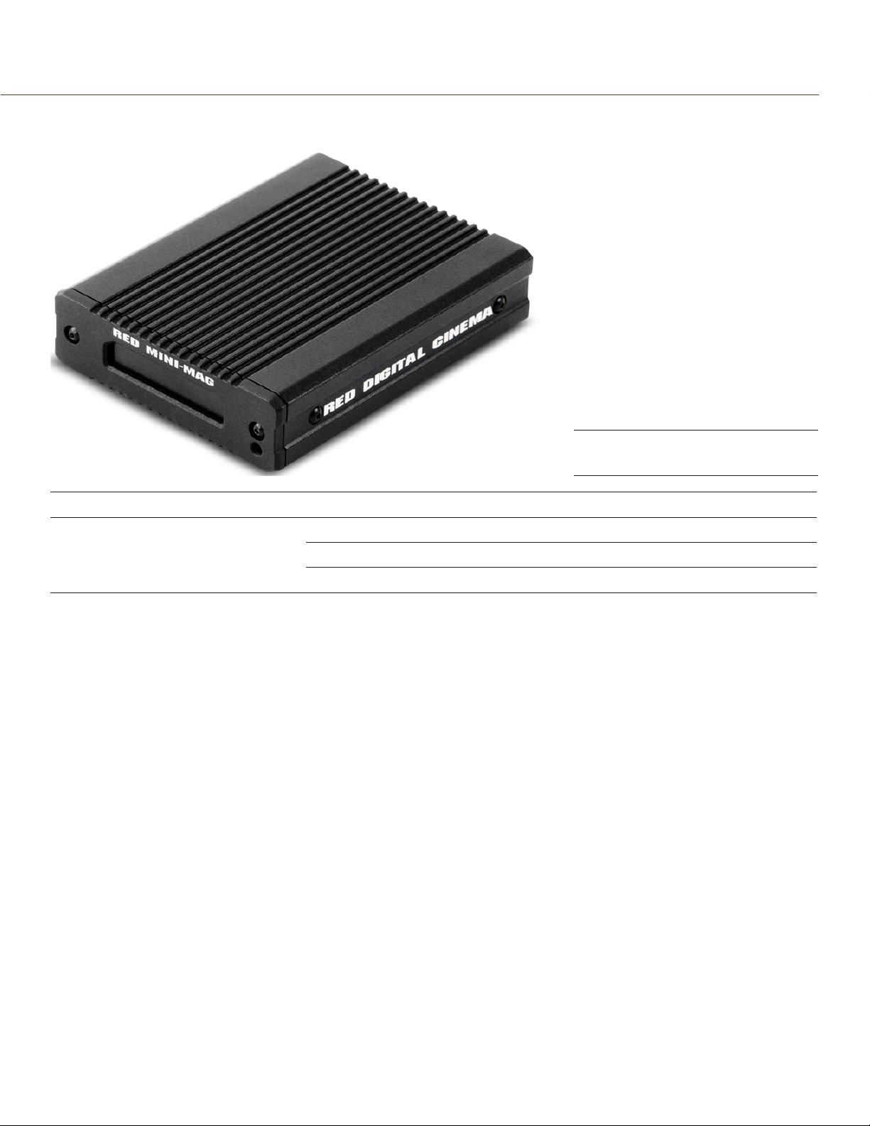
RED MINI-MAG
SIDE SSD MODULE
RED MINI-MAG SIDE SSD MODULE INCLUDED COMPONENTS
The item listed in the table below ships with the RED MINI-MAG SIDE SSD MODULE.
ITEM PART NUMBER
RED MINI-MAG SIDE SSD MODULE 720-0021
RED MINI-MAG SIDE SSD MODULE CONTROLS
This section describes the controls for all of the RED MINI-MAG modules.
CONTROL DESCRIPTION
User Key 1 Programmable key
User Key 1 + 2 Press: Eject Media
User Key 2 Programmable key
User Key 1 + 2 Press: Eject Media
REC button Programmable key
Full Press: Record Toggle
Half Press: AF Start
COPYRIGHT © 2014 RED.COM, INC
955-0047, REV-E | 10

RED DSMC MEDIA OPERATION GUIDE
RED MINI-MAG SIDE SSD MODULE CONNECTORS
This section describes the connectors for all of the RED MINI-MAG modules.
Each RED MINI-MAG modules mounts to the left side of the DSMC BRAIN. The rear face of this module features
a slot for inserting a RED MINI-MAG.
WARNING: DO NOT attempt to insert any media type except for the RED MINI-MAG, or any foreign objects, into
the SSD slot, as that may damage the RED MINI-MAG module or DSMC system.
The EVF/LCD connector on the front face of the RED MINI-MAG module provides digital vid-
eo, communications, and power interconnection between the DSMC and a RED EVF or RED LCD.
Due to the requirement for absolute data integrity, the pinout of the EVF/LCD connector is not published.
CONNECTOR DESCRIPTION COMPATIBLE PARTS PART NUMBERS
EVF/LCD connector VIEWFINDER output LCD/EVF CABLE (RIGHT-TO-
RIGHT) 7"
LCD/EVF CABLE (RIGHT-TO-
RIGHT) 12"
LCD CABLE 6' 790-0055
LCD CABLE 10' 790-0056
RED MINI-MAG slot Slot for inserting a RED MINI-MAG RED MINI-MAG 750-0053
790-0158
790-0162
RED MINI-MAG SIDE SSD MODULE LEDS
This section describes the LED for all of the RED MINI-MAG modules.
LED COLOR/FLASHING DESCRIPTION
Media Indicator LED Off No media present
Green Ready to record
Red Recording
Red slow flashing Recording; 25% media left
Red fast flashing Recording; 5% media left
Yellow Finalizing
Yellow flashing Accessing media (for example,
when formatting)
COPYRIGHT © 2014 RED.COM, INC 955-0047, REV-E | 11

RED DSMC MEDIA OPERATION GUIDE
RED STATION RED MINI-MAG
The RED STATION RED MINI-MAG is designed exclusively for offloading data from RED MINI-MAGS, and connects
to your computer via Firewire 800, eSATA 6G, or USB 3.0. Its compact design takes up less space than the
traditional RED STATION REDMAG 1.8" and fits easier into cases for storage.
RED STATION RED MINI-MAG
RED STATION RED MINI-MAG INCLUDED COMPONENTS
The items listed in the table below ship with the RED STATION RED MINI-MAG.
ITEM PART NUMBER
RED STATION RED MINI-MAG 750-0055
eSATA Data Cable (24") 790-0250
RED STATION USB 3.0 CABLE (24") 790-0314
RED STATION FW800 Cable (2") 790-0253
RED STATION FW800 Cable (24") 790-0251
RED STATION AC POWER ADAPTOR 790-0292
RED STATION USB TO DC POWER CABLE (24") 790-0316
COPYRIGHT © 2014 RED.COM, INC
955-0047, REV-E | 12

RED DSMC MEDIA OPERATION GUIDE
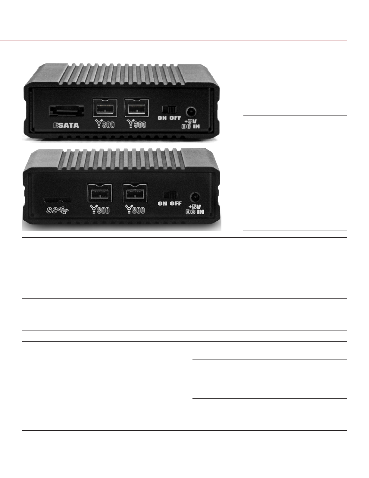
RED STATION RED MINI-MAG CONNECTORS AND CONTROLS
RED STATION RED MINI-MAG
(Rear)
CONNECTOR DESCRIPTION COMPATIBLE PARTS PART NUMBERS
eSATA 6G connec-
1
tor
FireWire 800 Connect to a computer or addi-
USB 3.0 slot Connect to computer via USB 3.0
On/Off Switch Turn on/off NA NA
+5 VDC IN +5 VDC power in RED STATION AC POWER ADAP-
RED MINI-MAG slot
(front)
1. Only Silicon Image or HighPoint SATA cards connect to the RED STATION RED MINI-MAG through eSATA.
Connect to a computer via an
eSATA connection
tional RED STATIONS via a FireWire
800 connection
connection
Slot for inserting a RED MINI-MAG RED MINI-MAG 750-0053
eSATA Data Cable (24") 790-0250
RED STATION FW800 Cable (2") 790-0253
RED STATION FW800 Cable (24") 790-0251
RED STATION USB 3.0 CABLE (24") 790-0314
790-0292
TOR
RED STATION USB TO DC POWER
CABLE (24")
790-0316
COPYRIGHT © 2014 RED.COM, INC 955-0047, REV-E | 13
RED DSMC MEDIA OPERATION GUIDE
RED STATION RED MINI-MAG LEDS
RED STATION RED MINI-MAG
LED COLOR/FLASHING DESCRIPTION
Power Indicator LED Off Powered off and turned off
Red Powered on and turned on
Red fast flashing Accessing media
COPYRIGHT © 2014 RED.COM, INC
955-0047, REV-E | 14

RED DSMC MEDIA OPERATION GUIDE
REDMAG 1.8" SSD
03
SYSTEM
REDMAG 1.8" SSD
The REDMAG 1.8" SSD media works with the DSMC 1.8" SSD SIDE MODULE and REAR SSD MODULE to
provide a fast and reliable recording medium.
The REDMAG 1.8" SSD is available in the following storage capacities: 48GB, 64GB, 128GB, 256GB, and
512GB.
REDMAG 1.8" SSD
REDMAG 1.8" SSD INCLUDED COMPONENTS
Each REDMAG 1.8" SSD ships with one (1) of the following:
ITEM PART NUMBER
REDMAG 1.8" SSD (48GB) 750-0044
REDMAG 1.8" SSD (64GB) 750-0025
REDMAG 1.8" SSD (128GB) 750-0021
REDMAG 1.8" SSD (240GB)
REDMAG 1.8" SSD (256GB) 750-0026
REDMAG 1.8" SSD (512GB)
1. The REDMAG 1.8" SSD (240GB) requires that your DSMC is on firmware v5.1.44 or later.
2. The REDMAG 1.8" SSD (512GB) is no longer available for purchase at red.com, but is still supported by RED.
COPYRIGHT © 2014 RED.COM, INC
1
2
750-0061
750-0037
955-0047, REV-E | 15

RED DSMC MEDIA OPERATION GUIDE
SSD MODULES
You can mount the REDMAG 1.8" SSD to the following modules:
DSMC 1.8" SSD SIDE MODULE
DSMC 1.8" SSD SIDE MODULE (DRAGON)
DSMC 1.8" SSD SIDE MODULE (CARBON FIBER DRAGON)
REAR SSD MODULE
DSMC 1.8" SSD SIDE MODULES
RED offers the following DSMC 1.8" SSD SIDE MODULES:
DSMC 1.8" SSD SIDE MODULE: Mounts to any standard aluminum DSMC BRAIN.
DSMC 1.8" SSD SIDE MODULE (DRAGON): Mounts to a DSMC with a RED DRAGON sensor, and is only avail-
able with a DSMC with a RED DRAGON sensor.
DSMC 1.8" SSD SIDE MODULE (CARBON FIBER DRAGON): Mounts to a carbon fiber DSMC BRAIN, and is only
available with a carbon fiber DSMC BRAIN.
Each DSMC 1.8" SSD SIDE MODULE attaches to the DSMC so that you can mount a REDMAG 1.8" SSD to
your camera.
Each DSMC 1.8" SSD SIDE MODULE has the same EVF/LCD LEMO connector, user keys, REC button, and
LED as the RED MINI-MAG SIDE SSD MODULE.
WARNING: The DSMC 1.8" SSD SIDE MODULE is NOT HOT SWAPPABLE, meaning you cannot remove or install
the module while the camera is powered on. Before installing or removing the module you MUST power down
the camera. Failure to do so may result in damage to the module or DSMC that will not be covered under warranty.
COPYRIGHT © 2014 RED.COM, INC
DSMC 1.8" SSD SIDE MODULE
(Rear and Front)
955-0047, REV-E | 16

RED DSMC MEDIA OPERATION GUIDE
DSMC 1.8" SSD SIDE MODULE INCLUDED COMPONENTS
The items listed in the table below ship with the DSMC 1.8" SSD SIDE MODULE.
ITEM PART NUMBER
DSMC 1.8" SSD SIDE MODULE 720-0013
Four (4) M3x0.5 x 6 mm Cap Screws NA
DSMC 1.8" SSD SIDE MODULE CONTROLS
This section describes the controls for all of the DSMC 1.8" SSD SIDE MODULES.
CONTROL DESCRIPTION
User Key 1 Programmable key
User Key 1 + 2 Press: Eject Media
User Key 2 Programmable key
User Key 1 + 2 Press: Eject Media
REC button Programmable key
Full Press: Record Toggle
Half Press: AF Start
DSMC 1.8" SSD SIDE MODULE
(Front)
COPYRIGHT © 2014 RED.COM, INC 955-0047, REV-E | 17

RED DSMC MEDIA OPERATION GUIDE
DSMC 1.8" SSD SIDE MODULE CONNECTORS
This section describes the connectors for all of the DSMC 1.8" SSD SIDE MODULES.
The DSMC 1.8" SSD SIDE MODULE mounts to the left side of the DSMC BRAIN. The rear face of this module
features a slot for inserting a REDMAG 1.8" SSD.
WARNING: DO NOT attempt to insert any media type except for the REDMAG 1.8" SSD, or any foreign objects,
into the SSD slot, as that may damage the DSMC 1.8" SSD SIDE MODULE or DSMC system.
The EVF/LCD connector on the front face of the DSMC 1.8" SSD SIDE MODULE provides digi-
tal video, communications, and power interconnection between the DSMC and a RED EVF or RED LCD.
Due to the requirement for absolute data integrity, the pinout of the EVF/LCD connector is not published.
DSMC 1.8" SSD SIDE MODULE
(Rear and Front)
CONNECTOR DESCRIPTION COMPATIBLE PARTS PART NUMBERS
EVF/LCD connector
(front)
REDMAG 1.8" SSD
slot (rear)
WARNING: Damage to the DSMC, side SSD module, or other components of the DSMC system caused by mixing
carbon fiber components with non-carbon-fiber components is not covered under warranty, and may void the
warranty for both the BRAIN and the side SSD module. For more information, go to “Mixing Carbon Fiber and
Aluminum Components” on page 8.
VIEWFINDER output LCD/EVF CABLE (RIGHT-TO-
RIGHT) 7"
LCD/EVF CABLE (RIGHT-TO-
RIGHT) 12"
LCD CABLE 6' 790-0055
LCD CABLE 10' 790-0056
Slot for inserting a
REDMAG 1.8" SSD
REDMAG 1.8" SSD (48GB) 750-0044
REDMAG 1.8" SSD (64GB) 750-0025
REDMAG 1.8" SSD (128GB) 750-0021
REDMAG 1.8" SSD (256GB) 750-0026
REDMAG 1.8" SSD (512GB) 750-0037
790-0158
790-0162
COPYRIGHT © 2014 RED.COM, INC
955-0047, REV-E | 18

RED DSMC MEDIA OPERATION GUIDE
DSMC 1.8" SSD SIDE MODULE LED
This section describes the LED for all of the DSMC 1.8" SSD SIDE MODULES.
DSMC 1.8" SSD SIDE MODULE
(Rear)
LED COLOR/FLASHING DESCRIPTION
Media Indicator LED Off No media present
Green Ready to record
Red Recording
Red slow flashing Recording; 25% media left
Red fast flashing Recording; 5% media left
Yellow Finalizing
Yellow flashing Accessing media (for example, when
formatting)
COPYRIGHT © 2014 RED.COM, INC 955-0047, REV-E | 19

RED DSMC MEDIA OPERATION GUIDE
REAR SSD MODULE
The REAR SSD MODULE secures onto the back of a MODULE ADAPTOR or a +1 ADAPTOR MODULE to serve
as a rear location for recording to a REDMAG 1.8" SSD. In the case that you are using cables or configurations
that make it difficult to access your DSMC 1.8" SSD SIDE MODULE, the REAR SSD MODULE is positioned to
make it easy to swap and record to a REDMAG 1.8" SSD.without interference.
The REAR SSD MODULE does not have any user keys or control buttons.
NOTE: The REAR SSD MODULE mounts only to a MODULE ADAPTOR or a +1 ADAPTOR MODULE.
REAR SSD MODULE
REAR SSD MODULE INCLUDED COMPONENTS
The item listed in the table below ships with the REAR SSD MODULE.
ITEM PART NUMBER
REAR SSD MODULE 720-0009
COPYRIGHT © 2014 RED.COM, INC
955-0047, REV-E | 20

RED DSMC MEDIA OPERATION GUIDE
REAR SSD MODULE CONNECTORS
The REAR SSD MODULE mounts to a MODULE ADAPTOR or a +1 ADAPTOR MODULE on the back of the
DSMC BRAIN. The side of the REAR SSD MODULE features a slot for inserting a REDMAG 1.8" SSD.
WARNING: DO NOT attempt to insert any media type except for the REDMAG 1.8" SSD, or any foreign objects,
into the SSD slot, as that may damage the REAR SSD MODULE or DSMC system.
CONNECTOR DESCRIPTION COMPATIBLE PARTS PART NUMBERS
SEARAYTM
connector (front)
SEARAY connector
(rear)
1/4-20 mounting
holes (top)
Lock (bottom) Use T20 Torx® driver to lock (CW)
REDMAG 1.8" SSD
slot (side)
Connects to complementary SEARAY connector on the
MODULE ADAPTOR; facilitates
communication between DSMC and
REAR SSD MODULE
Connects to complementary SEARAY connector on RED rear modules
Five (5) 1/4-20 mounting holes for
mounting the RED TOUCH or other
RED products
and unlock (CCW) the module
Slot for inserting a
REDMAG 1.8" SSD
MODULE ADAPTOR 720-0008
+1 ADAPTOR MODULE 720-0018
PRO BATTERY MODULE (DUAL) 720-0005
PRO BATTERY MODULE (QUAD) 720-0006
QUICKPLATE MODULE 790-0343
REDVOLT XL MODULE 740-0031
PRO I/O MODULE 720-0004
REDMOTE 770-0006
NA NA
T20 Torx driver NA
REDMAG 1.8" SSD (48GB) 750-0044
REDMAG 1.8" SSD (64GB) 750-0025
REDMAG 1.8" SSD (128GB) 750-0021
REDMAG 1.8" SSD (256GB) 750-0026
REDMAG 1.8" SSD (512GB) 750-0037
REAR SSD MODULE LED
LED COLOR/FLASHING DESCRIPTION
Media Indicator LED Off No media present
Green Ready to record
Red Recording
Red slow flashing Recording; 25% media left
Red fast flashing Recording; 5% media left
Yellow Finalizing
Yellow flashing Accessing media (for example,
when formatting)
COPYRIGHT © 2014 RED.COM, INC 955-0047, REV-E | 21

RED DSMC MEDIA OPERATION GUIDE
RED STATIONS
You can use the following items to offload data from your REDMAG 1.8" SSD and manage your media:
RED STATION REDMAG 1.8"
RED STATION REDMAG 1.8" (MINI)–ESATA
RED STATION REDMAG 1.8" (MINI)–USB 3.0
RED STATION REDMAG 2.5"
RED STATION BASE (provides power to RED STATIONS; is not a REDMAG 1.8" SSD reader)
RED STATION REDMAG 1.8"
The RED STATION REDMAG 1.8" reads and offloads data from your REDMAG 1.8" SSD to your hard drive
when connected to your computer. The RED STATION REDMAG 1.8" connects via eSATA, FireWire 800, or USB
2.0 to your laptop or desktop computer.
RED STATION REDMAG 1.8"
RED STATION REDMAG 1.8" INCLUDED COMPONENTS
The items listed in the table below ship with the RED STATION REDMAG 1.8".
ITEM PART NUMBER
RED STATION REDMAG 1.8" 750-0006
RED STATION RUBBER FEET SET 790-0293
eSATA Data Cable (24") 790-0250
RED STATION FW800 Cable (2") 790-0253
RED STATION FW800 Cable (24") 790-0251
RED STATION USB-TO-MINI USB CABLE (24”) 790-0315
RED STATION AC POWER ADAPTOR 790-0292
RED STATION USB TO DC POWER CABLE (24") 790-0316
RED STATION DC POWER COUPLER CABLE (2") 790-0249
COPYRIGHT © 2014 RED.COM, INC
955-0047, REV-E | 22

RED DSMC MEDIA OPERATION GUIDE
RED STATION REDMAG 1.8" CONNECTORS AND CONTROLS
RED STATION
REDMAG 1.8"
(Rear)
CONNECTOR DESCRIPTION COMPATIBLE PARTS PART NUMBERS
POWER Both connectors accept power
from any RED STATION
that is already connected to a
RED STATION BASE; can also output power to another RED STATION
in a stand-alone configuration or when powered by a
RED STATION BASE
eSATA connector1Connect to computer via an eSATA
connection
FireWire 800 Use either connector to connect to
a computer or additional RED STATIONS via a FireWire 800 connection
Mini USB slot Connect to a computer via a Mini
USB connection
On/Off Switch Turn on/off NA NA
+5 VDC IN +5 VDC power in RED STATION AC POWER ADAP-
RED STATION DC POWER COUPLER (2")
eSATA Data Cable (24") 790-0250
RED STATION FW800 Cable (2") 790-0253
RED STATION FW800 Cable (24") 790-0251
USB-TO-MINI USB CABLE (24") 790-0315
TOR
RED STATION USB TO DC POWER
CABLE (24")
790-0249
790-0292
790-0316
REDMAG 1.8" SSD
slot (front)
1. Only Silicon Image or HighPoint SATA cards connect to the RED STATION REDMAG 1.8" through eSATA.
COPYRIGHT © 2014 RED.COM, INC 955-0047, REV-E | 23
Slot for inserting a
REDMAG 1.8" SSD
REDMAG 1.8" SSD (48GB) 750-0044
REDMAG 1.8" SSD (64GB) 750-0025
REDMAG 1.8" SSD (128GB) 750-0021
REDMAG 1.8" SSD (256GB) 750-0026
REDMAG 1.8" SSD (512GB) 750-0037

RED DSMC MEDIA OPERATION GUIDE
RED STATION REDMAG 1.8" LEDS
RED STATION
REDMAG 1.8"
(Front)
LED COLOR/FLASHING DESCRIPTION
Power Indicator LED Off Powered off and turned off
Red Powered on and turned on
Red fast flashing Accessing media
RED STATION REDMAG 1.8" (MINI)
The RED STATION REDMAG 1.8" (MINI) reads and offloads data from your REDMAG 1.8" SSD to your hard
drive when connected to your computer. Compact form factor makes the RED STATION REDMAG 1.8" (MINI)
perfect for offloading your REDMAG 1.8" SSD when workspace is limited and portability makes all the difference.
The RED STATION REDMAG 1.8" (MINI) is available with either of the following sets of ports:
FireWire 800 and eSATA: P/N 750-0035
FireWire 800 and USB 3.0: P/N 750-0036
COPYRIGHT © 2014 RED.COM, INC
RED STATION
REDMAG 1.8" (MINI)
955-0047, REV-E | 24

RED DSMC MEDIA OPERATION GUIDE
RED STATION REDMAG 1.8" (MINI)-ESATA INCLUDED COMPONENTS
The items listed in the table below ship with the RED STATION REDMAG 1.8" (MINI)–ESATA.
ITEM PART NUMBER
RED STATION REDMAG 1.8"–ESATA 750-0035
eSATA Data Cable (24") 790-0250
RED STATION FW800 Cable (2") 790-0253
RED STATION FW800 Cable (24") 790-0251
RED STATION AC POWER ADAPTOR 790-0292
RED STATION USB TO DC POWER CABLE (24") 790-0316
RED STATION REDMAG 1.8" (MINI)-USB 3.0 INCLUDED COMPONENTS
The items listed in the table below ship with the RED STATION REDMAG 1.8" (MINI)–USB 3.0.
ITEM PART NUMBER
RED STATION REDMAG 1.8"–USB 3.0 750-0036
RED STATION USB 3.0 CABLE (24") 790-0314
RED STATION FW800 Cable (2") 790-0253
RED STATION FW800 Cable (24") 790-0251
RED STATION AC POWER ADAPTOR 790-0292
RED STATION USB TO DC POWER CABLE (24") 790-0316
COPYRIGHT © 2014 RED.COM, INC 955-0047, REV-E | 25
RED DSMC MEDIA OPERATION GUIDE
RED STATION REDMAG 1.8" (MINI) CONNECTORS AND CONTROLS
RED STATION REDMAG 1.8"
(MINI)–ESATA (Rear)
RED STATION REDMAG 1.8"
(MINI)–USB 3.0 (Rear)
CONNECTOR DESCRIPTION COMPATIBLE PARTS PART NUMBERS
eSATA connector1Connect to a computer via an
eSATA connection (only on P/N
750-0035)
USB 3.0 slot Connect to a computer via a USB
3.0 connection (only on P/N 750-
0036)
FireWire 800 Use either connector to connect to
a computer or additional RED STA-
TIONS via a FireWire 800 connec-
tion
On/Off Switch Turn on/off NA NA
+5 VDC IN +5 VDC power in RED STATION AC POWER ADAP-
REDMAG 1.8" SSD
slot (front)
Slot for inserting a
REDMAG 1.8" SSD
eSATA Data Cable (24") 790-0250
RED STATION USB 3.0 CABLE (24") 790-0314
RED STATION FW800 Cable (2") 790-0253
RED STATION FW800 Cable (24") 790-0251
790-0292
TOR
RED STATION USB TO DC POWER
CABLE (24")
REDMAG 1.8" SSD (48GB) 750-0044
REDMAG 1.8" SSD (64GB) 750-0025
790-0316
REDMAG 1.8" SSD (128GB) 750-0021
REDMAG 1.8" SSD (256GB) 750-0026
REDMAG 1.8" SSD (512GB) 750-0037
1. Only Silicon Image or HighPoint SATA cards connect to the RED STATION REDMAG 1.8" (MINI) through eSATA.
COPYRIGHT © 2014 RED.COM, INC
955-0047, REV-E | 26

RED DSMC MEDIA OPERATION GUIDE
RED STATION REDMAG 1.8" (MINI)
RED STATION
REDMAG 1.8”
(MINI)
(Front)
LED COLOR/FLASHING DESCRIPTION
Power Indicator LED Off Powered off and turned off
Red Powered on and turned on
Red fast flashing Accessing media
RED STATION REDMAG 2.5"
You can use the RED STATION REDMAG 2.5" to offload content from your REDMAG 1.8" SSD to a third-party
external 2.5" SSD or spinning hard drive. RED does not provide any 2.5" media or drives.
RED STATION REDMAG 2.5"
COPYRIGHT © 2014 RED.COM, INC 955-0047, REV-E | 27

RED DSMC MEDIA OPERATION GUIDE
RED STATION REDMAG 2.5" INCLUDED COMPONENTS
The items listed in the table below ship with the RED STATION REDMAG 2.5".
ITEM PART NUMBER
RED STATION REDMAG 2.5" 750-0007
RED STATION RUBBER FEET SET 790-0293
eSATA Data Cable (24") 790-0250
RED STATION FW800 Cable (2") 790-0253
RED STATION FW800 Cable (24") 790-0251
RED STATION USB-TO-MINI USB CABLE (24”) 790-0315
RED STATION AC POWER ADAPTOR 790-0292
RED STATION USB TO DC POWER CABLE (24") 790-0316
RED STATION DC POWER COUPLER CABLE (2") 790-0249
COMPATIBLE 2.5" HARD DRIVES
The following 2.5" hard drives are compatible with the RED STATION REDMAG 2.5":
Seagate 2.5" Desktop Hard Drive 5400 RPM, 320GB (Model number: ST9320325AS)
Seagate 2.5" Desktop Hard Drive 5400 RPM, 500GB (Model number: ST9500325AS)
Seagate 2.5" Desktop Hard Drive 7200 RPM, 250GB (Model number ST9250410AS)
Seagate 2.5" Desktop Hard Drive 7200 RPM, 320GB (Model number ST9320423AS)
Western Digital 2.5" Desktop Hard Drive 7200 RPM, 320GB (Black) (Model number: WD3200BJKT)
COPYRIGHT © 2014 RED.COM, INC
955-0047, REV-E | 28

RED DSMC MEDIA OPERATION GUIDE
RED STATION REDMAG 2.5" CONNECTORS AND CONTROLS
RED STATION
REDMAG 2.5"
(Rear)
CONNECTOR DESCRIPTION COMPATIBLE PARTS PART NUMBERS
POWER Both connectors accept power
from any RED STATION
that is already connected to a
RED STATION BASE; can also out-
put power to another RED STATION
in a stand-alone configura-
tion or when powered by a
RED STATION BASE
eSATA connector1Connect to computer via an eSATA
connection
FireWire 800 Use either connector to connect to
a computer or additional RED STA-
TIONS via a FireWire 800 connec-
tion
Mini USB slot Connect to computer via a Mini
USB connection
On/Off Switch Turn on/off NA NA
+5 VDC IN +5 VDC power in RED STATION AC POWER ADAP-
RED STATION DC POWER COUPLER (2")
eSATA Data Cable (24") 790-0250
RED STATION FW800 Cable (2") 790-0253
RED STATION FW800 Cable (24") 790-0251
USB-TO-MINI USB CABLE (24") 790-0315
TOR
RED STATION USB TO DC POWER
CABLE (24")
790-0249
790-0292
790-0316
2.5" Hard Drive slot
(front)
1. Only Silicon Image or HighPoint SATA cards connect to the RED STATION REDMAG 2.5" through eSATA.
COPYRIGHT © 2014 RED.COM, INC 955-0047, REV-E | 29
Slot for inserting a third-party 2.5"
SSD or spinning hard drive
NA NA
RED DSMC MEDIA OPERATION GUIDE
RED STATION REDMAG 2.5" LEDS
RED STATION
REDMAG 2.5”
(Front)
LED COLOR/FLASHING DESCRIPTION
Power Indicator LED Off Powered off and turned off
Red Powered on and turned on
Red fast flashing Accessing media
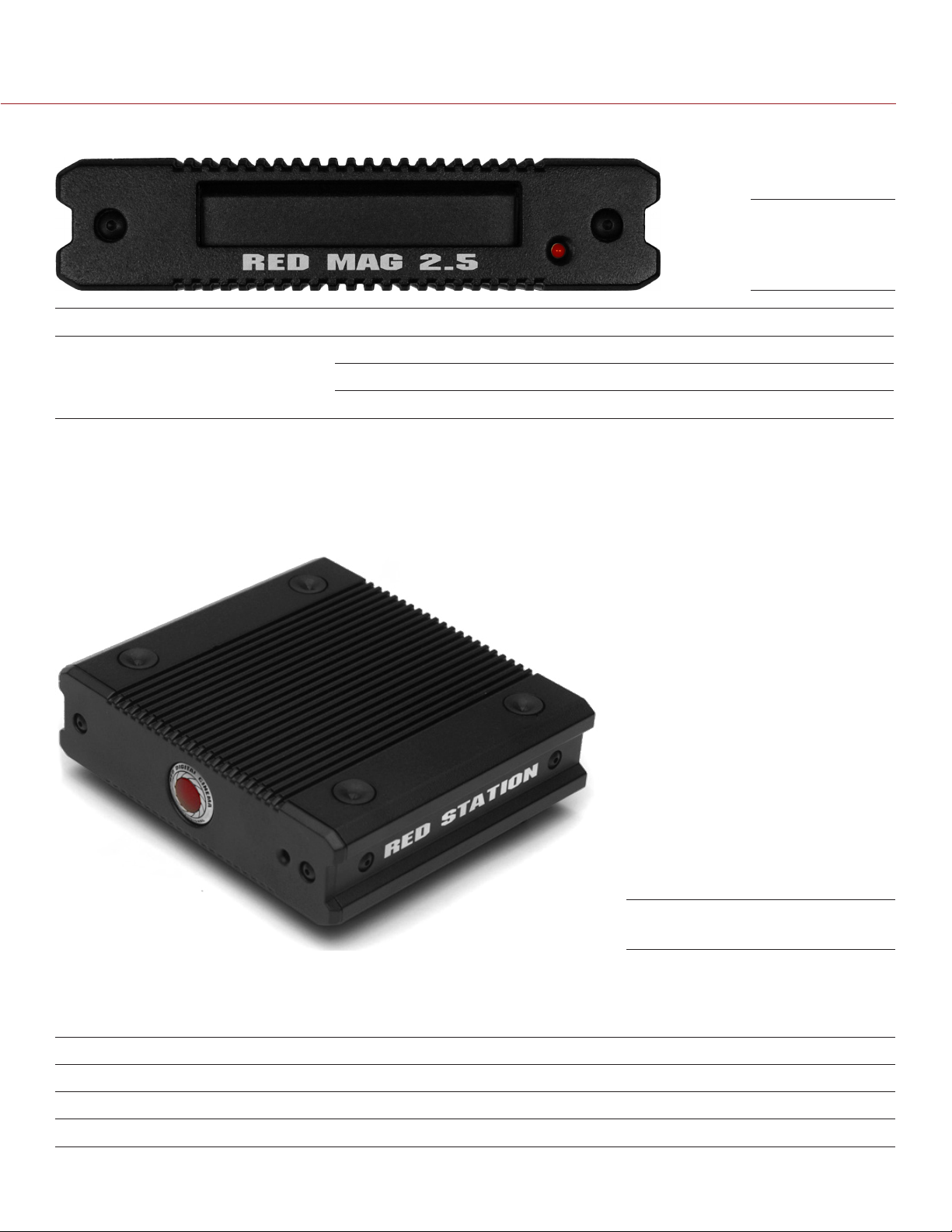
RED STATION BASE
The RED STATION BASE provides power to up to three (3) RED STATIONS (excluding the
RED STATION REDMAG 1.8" (MINI) and RED STATION RED MINI-MAG), eliminating the need to have AC power adaptors going to each module. This product is a great solution for those who are managing multiple RED
STATIONS and want to reduce cable clutter.
RED STATION BASE
RED STATION BASE INCLUDED COMPONENTS
The items listed in the table below ship with the RED STATION BASE.
ITEM PART NUMBER
RED STATION BASE 750-0004
RED STATION BASE AC POWER ADAPTOR 790-0308
RED STATION DC POWER COUPLER CABLE (2") 790-0249
COPYRIGHT © 2014 RED.COM, INC
955-0047, REV-E | 30

RED DSMC MEDIA OPERATION GUIDE
RED STATION BASE CONNECTORS AND CONTROLS
RED STATION BASE
(Rear)
CONNECTOR DESCRIPTION COMPATIBLE PARTS PART NUMBERS
POWER Allows RED STATION BASE to pow-
er up to three (3) RED STATIONS
On/Off Switch Turn on/off NA NA
+5 VDC IN +5 VDC power in RED STATION AC POWER ADAP-
RED STATION DC POWER COUPLER (2")
TOR
RED STATION USB TO DC POWER
CABLE (24")
790-0249
790-0292
790-0316
RED STATION BASE LEDS
RED STATION BASE
(Front)
LED COLOR/FLASHING DESCRIPTION
Power Indicator LED Off Powered off and turned off
Red Powered on and turned on
COPYRIGHT © 2014 RED.COM, INC 955-0047, REV-E | 31

RED DSMC MEDIA OPERATION GUIDE
INSTALL MEDIA
04
This section explains how to install the following modules to the DSMC BRAIN:
RED MINI-MAG SIDE SSD MODULE
Carbon Fiber RED MINI-MAG Side SSD Module
DSMC 1.8" SSD SIDE MODULE
DSMC 1.8" SSD SIDE MODULE (DRAGON)
DSMC 1.8" SSD SIDE MODULE (CARBON FIBER DRAGON)
REAR SSD MODULE
WARNING: The DSMC media modules are NOT HOT SWAPPABLE, meaning you cannot remove or install the
modules while the camera is powered on. Before installing or removing the modules, you MUST power down the
camera. Failure to do so may result in damage to the modules or DSMC that will not be covered under warranty.
MODULES
INSTALL SIDE MEDIA MODULES
ALUMINUM SIDE SSD MODULE INSTALLATION NOTES
The aluminum side SSD modules attach to the BRAIN using the same screws and tools, so you can easily switch
between these modules. You can attach the aluminum side SSD modules using either of the following screws:
Black M3x0.5 x 6 mm cap screws: These screws come with the standard aluminum EPIC BRAIN and ship with
the DSMC 1.8" SSD SIDE MODULE, but can be used with either the aluminum EPIC or SCARLET.
Black M3x0.5 x 5.5 mm cap screws: These screws come with the standard aluminum EPIC SCARLET, but can
be used with either the aluminum EPIC or SCARLET.
CARBON FIBER SIDE SSD MODULE INSTALLATION NOTES
Attach the carbon fiber side SSD modules to the carbon fiber DSMC BRAIN using only the red (colored) M3x0.5
x 6 mm cap screws that come with the carbon fiber DSMC BRAIN. The red (colored) screws are made of a different material than the black screws that come with the standard aluminum DSMC BRAIN, and are designed
to engage specifically with the lightweight panels of the carbon fiber BRAIN.
WARNING: DO NOT attach a carbon fiber side SSD module using any screws except the red (colored) screws that
are provided. Using other screws, including the screws that come with the standard aluminum DSMC BRAIN or
side SSD modules, will strip the through holes and damage the panels of the carbon fiber DSMC BRAIN.
WARNING: Damage to the DSMC BRAIN, carbon fiber side SSD module, or other components of the DSMC
system caused by using non-approved screws with the carbon fiber side SSD module is not covered under
warranty, and may void the warranty for both the BRAIN and the side SSD module.
WARNING: Damage to the DSMC BRAIN, aluminum side SSD module, or other components of the DSMC system
caused by mixing carbon fiber components with non-carbon-fiber components is not covered under warranty,
and may void the warranty for both the BRAIN and the side SSD module. For more information, go to “Mixing
Carbon Fiber and Aluminum Components” on page 8.
COPYRIGHT © 2014 RED.COM, INC
955-0047, REV-E | 32

RED DSMC MEDIA OPERATION GUIDE
REMOVE SIDE MEDIA MODULES
Follow the instructions in this section to remove any of the following modules from the DSMC BRAIN:
RED MINI-MAG SIDE SSD MODULE
Carbon Fiber RED MINI-MAG Side SSD Module
DSMC 1.8" SSD SIDE MODULE
DSMC 1.8" SSD SIDE MODULE (DRAGON)
DSMC 1.8" SSD SIDE MODULE (CARBON FIBER DRAGON)
REQUIRED TOOL: T10 Torx® driver
1. Power down the camera.
2. Use a T10 Torx driver to remove the four (4) cap screws that attach the module to the BRAIN in a cross
pattern. The screw types for the side SSD modules are listed below:
‒ Aluminum side SSD modules: Black M3x0.5 x 6 mm or M3x0.5 x 5.5 mm cap screws.
‒ Carbon fiber side SSD modules: Red M3x0.5 x 6 mm cap screws that come with the carbon fiber DSMC
BRAIN.
Remove Screws
3. Remove the module from the DSMC BRAIN.
4. Inspect the connections and pins on the DSMC BRAIN and ensure that they are clean and undamaged.
NOTE: DO NOT remove the two (2) red and black tamper-proof stickers.
Inspect Connections
COPYRIGHT © 2014 RED.COM, INC 955-0047, REV-E | 33

RED DSMC MEDIA OPERATION GUIDE
ATTACH SIDE MEDIA MODULES
Follow the instructions in this section to attach any of the following modules to the DSMC BRAIN:
RED MINI-MAG SIDE SSD MODULE
Carbon Fiber RED MINI-MAG Side SSD Module
DSMC 1.8" SSD SIDE MODULE
DSMC 1.8" SSD SIDE MODULE (DRAGON)
DSMC 1.8" SSD SIDE MODULE (CARBON FIBER DRAGON)
WARNING: DO NOT attach the carbon fiber side SSD module using any screws except the red screws that are
provided. Using other screws, including the screws that come with the standard aluminum DSMC BRAIN or side
SSD modules, will strip the through holes and damage the panels of the carbon fiber BRAIN. For more information, go to “Carbon Fiber Side SSD Module Installation Notes” on page 32.
WARNING: Damage to the DSMC, side SSD module, or other components of the DSMC system caused by mixing
carbon fiber components with non-carbon-fiber components is not covered under warranty, and may void the
warranty for both the BRAIN and the side SSD module. For more information, go to “Mixing Carbon Fiber and
Aluminum Components” on page 8.
REQUIRED TOOL: T10 Torx® driver
1. Place the side media module on the DSMC BRAIN, so that the mounting holes of the module align with the
screw holes of the DSMC BRAIN.
2. Use a T10 Torx driver to tighten the four (4) screws by about two (2) turns in a cross pattern. DO NOT FULLY
TIGHTEN.
The screw types for the side SSD modules are listed below:
‒ Aluminum side SSD modules: Black M3x0.5 x 6 mm or M3x0.5 x 5.5 mm cap screws.
‒ Carbon fiber side SSD modules: Red M3x0.5 x 6 mm cap screws that come with the carbon fiber DSMC
BRAIN.
Tighten Screws
3. Tighten the four (4) cap screws evenly. DO NOT exceed 70 in-oz, or damage may occur.
WARNING: DO NOT OVERTIGHTEN.
4. Insert the SSD in the SSD slot on the back of the side media module:
‒ RED MINI-MAG module: Install the RED MINI-MAG.
‒ DSMC 1.8" SSD SIDE MODULE: Install the REDMAG 1.8" SSD.
NOTE: DO NOT attempt to insert the RED MINI-MAG in any DSMC 1.8" SSD SIDE MODULE, and do not attempt to insert the REDMAG 1.8" SSD in any RED MINI-MAG module.
COPYRIGHT © 2014 RED.COM, INC
955-0047, REV-E | 34

RED DSMC MEDIA OPERATION GUIDE
INSTALL THE REAR SSD MODULE
The REAR SSD MODULE attaches to the DSMC system the same way that the other rear modules attach to the
system. For more information about installing rear DSMC modules, see the DSMC Operation Guide available at
www.red.com/downloads.
NOTE: DO NOT attempt to insert the RED MINI-MAG in the REAR SSD MODULE.
REAR SSD MODULE
EJECT MEDIA FROM CAMERA (UNMOUNT)
IMPORTANT: To ensure data integrity, media must always be unmounted prior to removal from the camera. This
ensures that power is removed from the digital media and any open data files are closed. Failure to properly
unmount media may result in lost data or corrupted files.
Removing an SSD without first unmounting it will not physically damage the media, however it does increase
the risk of file corruption, so it’s good operational practice to unmount the media if possible before removing or
disconnecting. Unmounting the digital media takes a few seconds, protects the integrity of your recorded data,
and helps clips mount instantly to your workstation in post-production.
NOTE: Improper removal of media without first unmounting the SSD will result in a warning notification: “Media
removed without first ejecting. Data integrity risk.” Always unmount media before physically removing the disk
to protect your media and footage.
To eject media, follow the instructions below:
1. Eject the media using one of the following modules:
‒ REDMOTE/Touchscreen LCD: Go to Menu > Media > Eject Media.
‒ DSMC SIDE HANDLE: Press User Key 7 (lowest of the system keys). The default function for this key is Eject
Media; however, you can remap this key.
‒ Side media module: Press User Key 1 + 2. The default function for this key combination is Eject Media;
however, you can remap this key combination.
When media is ejected, Viewfinder output(s) display “Media ejected successfully. It is now safe to remove
media”.
2. Remove media from the camera.
COPYRIGHT © 2014 RED.COM, INC 955-0047, REV-E | 35

RED DSMC MEDIA OPERATION GUIDE
FORMAT
05
MEDIA
OVERVIEW
The DSMC records REDCODE RAW compressed MOTION clips and STILL images, time code, multi-channel
audio, and metadata to RED MINI-MAGS and REDMAG 1.8" SSDS.
Record duration depends on resolution, REDCODE, and frame rate. A 64GB REDMAG 1.8" SSD typically provides 24 minutes of 24 FPS 5K RAW recording.
Each clip is recorded with a unique name in a clip folder with the extension .RDC. This folder contains all appropriate information describing the clip, including one or more REDCODE RAW .R3D files and all color grading
metadata and other system level metadata such as lens and location information.
The individual clip folders are placed in a folder (root directory) on the digital media. This folder has the extension .RDM. Since the .RDM folder contains all the recorded clips, you can copy all clips from the SSD to other
media by simply copying the .RDM folder.
IMPORTANT: After connecting a RED MINI-MAG or REDMAG 1.8" SSD to the camera and BEFORE recording,
format the SSD using the camera (even if formatting was previously performed on a computer).
FORMAT (ERASE) MEDIA IN-CAMERA
You must format your SSD (media) before recording to it. Formatting is performed in-camera, although media
may be erased on a computer, allowing the camera to just add the necessary project profile and clip log data.
Media formatted in-camera uses a name and root volume in the format:
Camera Letter + Reel Number + Month + Day + **, where ** represents two random alphanumeric charac-
ters generated by the camera to prevent any possibility of duplicate names being created. For example:
A001_0512A6.RDM.
IMPORTANT: Media must always be unmounted prior to removal from the camera. This ensures that power is removed from the digital media and any open data files are closed. Failure to properly unmount media may result
in lost data or corrupted files.
FORMAT MEDIA
IMPORTANT: Ensure that data is backed up before formatting media, since formatting erases all data on the SSD.
1. Insert the REDMAG 1.8" SSD or RED MINI-MAG into the media slot on a media module. Ensure that the
RED logo is facing outward (away from camera body). Insert the SSD firmly into its slot, but without using
excessive force to prevent damage.
NOTE: When fully inserted, the SSD protrudes slightly from the SSD slot.
2. When an SSD is inserted into the camera, the camera recognizes if the media is unformatted:
‒ LCD, EVF and external monitors: The word “NONE” displays twice (when no media is present, “NONE ---”
displays).
‒ REDMOTE: The word “NONE” displays twice (when no media is present, “NONE ---” displays).
‒ DSMC SIDE HANDLE: The message “NA” displays (when no media present, also displays “NA”).
3. Go to Menu > Media.
COPYRIGHT © 2014 RED.COM, INC
955-0047, REV-E | 36

RED DSMC MEDIA OPERATION GUIDE
4. Select an option from the Select Media drop-down menu.
5. Select Format Media.
6. Select the following options to add camera identity information and 3D position properties:
‒ Reel No: Select a value in the range 1–999.
‒ Cam ID: Select a letter in the range A-Z to identify the camera.
‒ Cam Pos: Identify the camera position as Right, Left, or Center. Default is Center.
‒ Edge Timecode Start: Manually enter an Edge Timecode Start value (seldom used).
7. Select Format. (The Format button also displays the number of clips that will be deleted during formatting,
if any clips are on the SSD).
8. A dialog box displays and warns you that all clips will be deleted during formatting. Select Format to con-
tinue.
Formatting takes about 10 seconds. Once formatting is complete, the Viewfinder output(s) display the fol-
lowing message: “The media was successfully re-formatted and is ready for immediate use”.
COPYRIGHT © 2014 RED.COM, INC 955-0047, REV-E | 37

RED DSMC MEDIA OPERATION GUIDE
SECURE FORMAT MEDIA
IMPORTANT: Ensure that data is backed up before formatting media, since formatting erases all data on the SSD.
Secure format is a low-level format that rebuilds the SSD file system. It should only be used if the performance
of the SSD is in question.
To perform a secure format, follow the instructions below:
1. Go to Menu > Media > Utils.
2. Select Secure Format.
3. Continue to format the media as you would for a normal media format. For more information, go to “Format
Media” on page 36.
FORMAT (ERASE) MEDIA VIA COMPUTER
RED recommends that you only format your SSD via computer if the SSD cannot mount to the camera.
NOTE: If the media was formatted using a secure format, you cannot format the media using an external source.
You must format the media in-camera. For more information on formatting the media in-camera, go to “Format
(Erase) Media In-Camera” on page 36.
FORMAT MEDIA (MACINTOSH OS X)
NOTE: A Mac can format an SSD as MS-DOS (FAT) only when the SSD is already formatted as FAT32 or MS-
DOS (FAT).
IMPORTANT: Ensure that data is backed up before formatting media, since formatting erases all data on the SSD.
1. Connect the RED MINI-MAG or REDMAG 1.8" SSD to your computer. For more information, go to “Offload
Media” on page 42.
2. Open the Disk Utility.
3. Select the drive.
4. Click the Erase tab.
5. Select MS-DOS (FAT) from the Volume Format drop-down menu.
NOTE: The camera will overwrite any name that you add to the SSD.
IMPORTANT: Before performing the next step, double-check that this is the correct SSD from which you want
to erase data.
COPYRIGHT © 2014 RED.COM, INC
955-0047, REV-E | 38

RED DSMC MEDIA OPERATION GUIDE
6. Click Erase.
7. When the dialog box opens, click Erase.
8. After the media is erased, click Unmount.
9. Eject the SSD from the computer.
NOTE: Properly eject/unmount the SSD from the computer before physically removing the SSD from the RED
STATION or turning off the RED STATION.
10. Remove the SSD from the RED STATION or RED STATION RED MINI-MAG.
11. Format the SSD in-camera. For more information on formatting the media in-camera, go to “Format (Erase)
Media In-Camera” on page 36.
FORMAT MEDIA (WINDOWS)
NOTE: A PC can format an SSD as FAT32 only when the SSD capacity is 64GB or less, due to the constraints
of the file system.
IMPORTANT: Ensure that data is backed up before formatting media, since formatting erases all data on the SSD.
1. Connect the RED MINI-MAG or REDMAG 1.8" SSD to your computer. For more information, go to “Offload
Media” on page 42.
2. Open My Computer.
3. Right-click the SSD icon and select Format.
IMPORTANT: Before performing the next step, double-check that this is the correct SSD from which you want
to erase data.
4. Select FAT32 from the File System drop-down menu.
5. Click Start.
6. Eject the SSD from the computer.
NOTE: Properly eject/unmount the SSD from the computer before physically removing the SSD from the RED
STATION or turning off the RED STATION.
7. Remove the SSD from the RED STATION or RED STATION RED MINI-MAG.
COPYRIGHT © 2014 RED.COM, INC 955-0047, REV-E | 39

RED DSMC MEDIA OPERATION GUIDE
8. Format the SSD in-camera. For more information on formatting the media in-camera, go to “Format (Erase)
Media In-Camera” on page 36.
CLIP NAMING CONVENTIONS
When you record a clip, the camera creates a unique name for the clip folder that uses the format described
in the table below:
NAME DESCRIPTION EXAMPLE
Camera Letter Menu > Media > Format Media > Cam ID A
Reel Number Menu > Media > Format Media > Reel ID 004
Clip Number The clip number increments by 1 C001
Month Month that the clip is recorded 12
Day Day that the clip is recorded 23
Two Characters Two random alphanumeric characters generated by the camera to prevent
any possibility of duplicate names being created
RDC Clip folder extension RDC
For example, a sequence of clip folders within a media folder on Camera A may look like this:
A001_C001_05026M.RDC
A001_C002_0502CE.RDC
A001_C003_0502R5.RDC
6M
MULTI CAMERA SHOOTS
The scheme provides flexibility to uniquely identify clips from different cameras on a multi-camera shoot. For
example, three cameras, slated as camera A, camera B, and camera C respectively, can generate these easily
recognizable clips on their respective SSDs:
A001_C001_0502**.RDC
B001_C001_0502**.RDC
C001_C001_0502**.RDC
3D (STEREO) CAMERA SHOOTS
The scheme also allows unique identification of clips from left and right eye cameras on a stereo shoot. For
example, two cameras, both slated as Camera S, can generate these easily recognizable clips on their respective SSDs:
S001_L001_0502**.RDC
S001_R001_0502**.RDC
METADATA
The following metadata is recorded for each frame of each clip:
Clip Name
Time Code
Date and GMT
Lens and Shutter Speed/Angle Parameters
Audio Configuration
Firmware Version Number
COPYRIGHT © 2014 RED.COM, INC
955-0047, REV-E | 40

RED DSMC MEDIA OPERATION GUIDE
Media Serial Number
LTC User Bits (three 32-bit word reg-dump from ISP)
S4i Static Data
S4i Dynamic Data
GMT Time/Data
RGB Curves
Shadow Control
Luma Curve
Lens Name, Brand, ID, Near Focus, Far Focus
Camera Network Name
Production Name
Director Name
DP Name
Copyright
Unit
Camera Name
Location
Scene
Take
Accelerometer Data
Gyro Data
MEDIA CAPACITY REMAINING STATUS
The Viewfinder output(s) display the remaining media capacity in the Media indicator:
Green: 11% or more
Yellow: 6%–10%
Red: 5% or less
NOTE: When media is full, the Media Indicator LED on the media module flashes red.
COPYRIGHT © 2014 RED.COM, INC 955-0047, REV-E | 41

RED DSMC MEDIA OPERATION GUIDE
OFFLOAD
06
MEDIA
CONNECT RED MINI-MAGS TO YOUR COMPUTER
This section explains how to connect a RED MINI-MAG to your computer using a RED STATION RED MINI-MAG.
NOTE: You can daisy-chain most FireWire storage devices, including RED STATION RED MINI-MAGS and RED
STATIONS (for REDMAG 1.8" SSDS).
1. Place RED STATION RED MINI-MAG on a firm, flat surface.
2. Connect the RED STATION RED MINI-MAG to a computer using one of the following data connectors:
WARNING: DO NOT connect more than one (1) data cable between one (1) RED STATION RED MINI-MAG
and the computer.
CONNECTOR CABLE (INCLUDED WITH
RED STATION RED MINI-MAG)
eSATA eSATA Data Cable (24") After connecting via eSATA, it may take up to 15
FireWire 800 RED STATION FW800 Cable (2")
RED STATION FW800 Cable (24")
NOTES
seconds for the media to display on the computer.
The computer supplies power to the
RED STATION RED MINI-MAG via the FireWire
800 connection, so it’s not necessary to use
the RED STATION AC POWER ADAPTOR.
However, RED recommends using the power
adaptor for optimal performance.
You can use the 2" FireWire 800 cables (in-
cluded with each RED STATION) to daisychain the RED STATIONS. Then, use one (1)
FireWire 800 cable to connect one (1) RED
STATION to the computer. The computer then
recognizes each RED STATION through a single FireWire connection.
USB 3.0 RED STATION USB 3.0 CABLE (24") If connecting to the computer using a differ-
ent Mini USB cable than provided, power the
RED STATION RED MINI-MAG with the RED STATION
AC POWER ADAPTOR.
3. If using an eSATA connection, power the RED STATION RED MINI-MAG with either of the following power cables:
‒ RED STATION AC POWER ADAPTOR
‒ RED STATION USB TO DC POWER CABLE (24")
4. Set the ON/OFF switch on the back of the RED STATION RED MINI-MAG to ON.
5. Install the RED MINI-MAG in the media slot on the front panel of the RED STATION RED MINI-MAG.
6. The computer recognizes the inserted RED MINI-MAG and displays the RED MINI-MAG as a new drive.
7. To offload data from the SSD, go to “Offload Data From Media to Your Computer” on page 45.
COPYRIGHT © 2014 RED.COM, INC
955-0047, REV-E | 42

RED DSMC MEDIA OPERATION GUIDE
CONNECT REDMAG 1.8" SSDS TO YOUR COMPUTER
This section explains how to connect a REDMAG 1.8" SSD to your computer using the following RED STATIONS:
RED STATION REDMAG 1.8"
RED STATION REDMAG 1.8" (MINI)–ESATA
RED STATION REDMAG 1.8" (MINI)–USB 3.0
RED STATION REDMAG 2.5"
NOTE: You can daisy-chain most FireWire storage devices, including RED STATION RED MINI-MAGS and RED
STATIONS (for REDMAG 1.8" SSDS).
SET UP RED STATIONS WITH RED STATION BASE
NOTE: The RED STATION BASE provides power to up to three (3) RED STATIONS (excluding the
RED STATION REDMAG 1.8" (MINI) and RED STATION RED MINI-MAG) using the RED STATION DC POWER COUPLER (2") that’s included with the RED STATION BASE.
1. Place RED STATION BASE on a firm, flat surface.
2. Place up to three (3) of the following RED STATIONS on top of the RED STATION BASE, aligning the four
(4) bottom pegs with the four (4) rubber pads on top of the RED STATION BASE:
‒ RED STATION REDMAG 1.8"
‒ RED STATION REDMAG 2.5"
3. Firmly press down on each RED STATION to insert the pegs into the rubber pads, creating one stacked unit.
4. Plug the RED STATION DC POWER COUPLER (2") into the POWER connector on the RED STATION BASE
and one POWER connector of the RED STATION directly on top of the RED STATION BASE.
5. Use RED STATION DC POWER COUPLERS (2") to daisy-chain any remaining RED STATIONS by plugging
the cables into one POWER connector on each RED STATION.
6. Connect the RED STATIONS to a computer using one of the following data connectors:
WARNING: DO NOT connect more than one (1) data cable between one (1) RED STATION and the computer.
CONNECTOR CABLE (INCLUDED WITH RED STATION) NOTES
eSATA eSATA Data Cable (24") After connecting via eSATA, it may take up to 15
seconds for the media to display on the computer.
FireWire 800 RED STATION FW800 Cable (2")
RED STATION FW800 Cable (24")
Mini USB USB-TO-MINI USB CABLE (24") NA
7. Set the ON/OFF switch on the back of each RED STATION and the RED STATION BASE to ON.
NOTE: When the ON/OFF switches on all of the RED STATIONS are set to ON, the ON/OFF switch on the
RED STATION BASE turns the RED STATIONS on/off.
8. Install the REDMAG 1.8" SSD in the media slot on the front panel of the RED STATION.
9. The computer recognizes the inserted SSD media and displays each SSD as a new drive.
10. To offload data from the SSD, go to “Offload Data From Media to Your Computer” on page 45.
COPYRIGHT © 2014 RED.COM, INC 955-0047, REV-E | 43
You can use the 2" FireWire 800 cables (included
with each RED STATION) to daisy-chain the RED
STATIONS. Then, use one (1) FireWire 800 cable
to connect one (1) RED STATION to the computer. The computer then recognizes each RED
STATION through a single FireWire connection.

RED DSMC MEDIA OPERATION GUIDE
SET UP STAND-ALONE RED STATIONS (WITHOUT RED STATION BASE)
This section explains how to connect a REDMAG 1.8" SSD to your computer using the following RED STATIONS without a RED STATION BASE:
RED STATION REDMAG 1.8"
RED STATION REDMAG 1.8" (MINI)–ESATA
RED STATION REDMAG 1.8" (MINI)–USB 3.0
RED STATION REDMAG 2.5"
To offload media, follow the instructions below:
1. Place RED STATION on a firm, flat surface.
2. Connect the RED STATION to a computer using one of the following data connectors:
WARNING: DO NOT connect more than one (1) data cable between one (1) RED STATION and the computer.
CONNECTOR CABLE (INCLUDED WITH RED STATION) NOTES
eSATA eSATA Data Cable (24") After connecting via eSATA, it may take up to 15
seconds for the media to display on the computer.
FireWire 800 RED STATION FW800 Cable (2")
RED STATION FW800 Cable (24")
Mini USB USB-TO-MINI USB CABLE (24”) If connecting to the computer using a different
USB 3.0
(RED STATION
REDMAG 1.8"
(MINI) only )
3. If using an eSATA connection, power the RED STATION with either of the following power cables:
‒ RED STATION AC POWER ADAPTOR
‒ RED STATION USB TO DC POWER CABLE (24")
4. If offloading a REDMAG 1.8" SSD (48GB) or a REDMAG 1.8" SSD (512GB), power the RED STATION with a
RED STATION USB TO DC POWER CABLE (24"). Using an eSATA or USB connection alone may not power
the RED STATION.
5. Set the ON/OFF switch on the back of the RED STATION to ON.
6. Install the REDMAG 1.8" SSD in the media slot on the front panel of the RED STATION.
7. The computer recognizes the inserted SSD media and displays the SSD as a new drive.
8. To offload data from the SSD, go to “Offload Data From Media to Your Computer” on page 45.
RED STATION USB 3.0 CABLE (24") If connecting to the computer using a different
The computer supplies power to the RED
STATION via the FireWire 800 connection, so
it’s not necessary to use the RED STATION
AC POWER ADAPTOR. However, RED recommends using the power adaptor for optimal
performance.
You can use the 2" FireWire 800 cables (in-
cluded with each RED STATION) to daisychain the RED STATIONS. Then, use one (1)
FireWire 800 cable to connect one (1) RED
STATION to the computer. The computer then
recognizes each RED STATION through a single FireWire connection.
Mini USB cable than provided, power the RED
STATION with the RED STATION AC POWER
ADAPTOR.
Mini USB cable than provided, power the RED
STATION with the RED STATION AC POWER
ADAPTOR.
COPYRIGHT © 2014 RED.COM, INC
955-0047, REV-E | 44

RED DSMC MEDIA OPERATION GUIDE
OFFLOAD DATA FROM MEDIA TO YOUR COMPUTER
1. Connect the RED MINI-MAG or REDMAG 1.8" SSD to your computer.
2. Copy the complete .RDM folder on the SSD to the archive storage media. This copies all the media and
metadata files.
NOTE: You do not need to copy the log, magazine profile, or presets files, but you can if you choose.
3. Properly eject/unmount the RED MINI-MAG from the computer before physically removing the RED MINI-MAG
from the RED STATION RED MINI-MAG or turning off the RED STATION RED MINI-MAG.
RED WATCHDOG
On Mac computers with REDCINE-X PRO installed, RED Watchdog mounts the SSD as read-only by default,
which means that you are unable to write files (including firmware upgrade files) to the SSD. RED Watchdog is
identified by the RED Coin icon located on the right side of the Mac Menu Bar.
To enable you to read/write to the SSD on a Mac, follow the instructions below:
1. Click the RED Watchdog icon.
2. Select Preferences.
3. Select Read-Write from the Mount RED Mags drop-down menu.
COPYRIGHT © 2014 RED.COM, INC 955-0047, REV-E | 45

RED DSMC MEDIA OPERATION GUIDE
UPGRADE SSD
07
Your RED SSD functionality may be upgraded by installing the latest firmware. Currently, RED only offers a firmware upgrade for the REDMAG 1.8" SSD (512GB).
Make a habit of frequently visiting www.red.com/downloads to check for new versions of SSD firmware, up-
dated operation guides, and post-production software.
FIRMWARE
VERIFY CURRENT SSD FIRMWARE
To see the firmware version that is currently installed on your SSD, go to Menu > Settings > Maintenance > System
Status > Media Info. The current firmware (Media Firmware Revision) version displays.
This is the complete list of information that displays on the Media Info screen:
Media Status: Active media, module type.
Media Name: Storage capacity, SSD type, and version/revision of the SSD.
Serial Number: Serial number of the SSD.
Media Firmware Revision: Firmware version on the SSD.
Media Size: Total capacity on the SSD.
Media Space Available for Recording: Total capacity left on the SSD that can be recorded to.
Maximum Data Rate: The maximum data rate when writing files to the SSD.
NOTE: When an SSD is not attached, the Media Info tab displays the following: “No Active Media Found”.
COPYRIGHT © 2014 RED.COM, INC
955-0047, REV-E | 46

RED DSMC MEDIA OPERATION GUIDE
UPGRADE REDMAG 1.8" SSD (512GB) FIRMWARE
NOTE: Offload any data from the SSD before you upgrade it.
NOTE: Upgrade the DSMC to firmware 5.1.44 or later before you upgrade SSD firmware.
1. Power up the DSMC, insert the REDMAG 1.8" SSD (512GB) into the DSMC, and format the SSD.
2. Properly eject the SSD from the DSMC.
3. Connect the SSD to your computer.
NOTE: On Mac computers with REDCINE-X PRO installed, RED Watchdog mounts the SSD as Read-Only
by default, which means that you are unable to write files (including firmware upgrade files) to the SSD.
Change the Mount preference to Read-Write before attempting to copy firmware to the SSD.
4. Download the REDMAG 1.8" SSD (512GB) firmware from www.red.com/downloads.
5. Unzip the file.
6. Copy the .rmf file to the top level of the SSD directory.
7. Eject or unmount the SSD, and then remove the SSD.
8. Insert the SSD with .rmf file into your DSMC and verify that the SSD mounts properly.
9. Go to Menu > Settings > Maintenance > Upgrade > Media.
10. Select Yes and verify that the operation completes without error.
11. Remove the SSD from the camera as instructed by the on-screen instructions.
12. Re-insert the SSD into the DSMC.
13. Go to Menu > Settings > Maintenance > System Status > Media Info and verify that the Media Firmware Revi-
sion listed matches the firmware version that you downloaded.
14. Format the SSD before use.
COPYRIGHT © 2014 RED.COM, INC 955-0047, REV-E | 47

RED DSMC MEDIA OPERATION GUIDE
TROUBLESHOOT
08
This chapter explains how to troubleshoot media for your DSMC. If you continue to experience issues after
troubleshooting, please file a support ticket at support.red.com.
MEDIA
IN-CAMERA ERRORS
NO MEDIA ATTACHED
The message “No Media Attached” displays if media is not present or not formatted when pressing the Record
button. To resolve this issue, perform one of the following:
If the SSD is not connected, connect the SSD to the camera.
If the SSD is already connected, format the SSD and attempt to record again. For more information about
formatting media, go to “Format Media” on page 36.
RECORDING HALTED: RECORD ERROR–SHUTDOWN
The message “Recording Halted: Record Error–Shutdown” displays if the SSD is removed while recording or
the connection to the DSMC is interrupted during recording. To resolve this issue, follow the instructions below:
1. Power down the camera.
2. Remove the SSD module from the camera.
3. Inspect connectors for damage.
4. Reconnect the SSD module to the camera and install the SSD.
5. Power up the camera.
6. Ensure that the SSD is recognized; reformat the SSD if necessary.
7. Resume recording.
NOTE: DO NOT remove the SSD while the camera is recording.
NOTE: If the problem persists, try recording with another SSD.
MEDIA DOES NOT MOUNT TO CAMERA
If the media does not mount to your DSMC, perform one or more of the following:
Reformat the SSD on the computer. For more information about formatting media on the computer, go to
“Format (Erase) Media Via Computer” on page 38.
Perform a system restore, and then remove and reattach the media module.
Use an alternate media module.
Use an alternate DSMC.
WARNING: If the problem persists after reformatting the SSD and attempting to mount the SSD on an alternate
DSMC, the SSD is likely damaged or otherwise compromised. DO NOT attempt to record to an SSD that is experiencing these problems. Any footage that is recorded to the SSD may be lost, damaged, or unrecoverable.
COPYRIGHT © 2014 RED.COM, INC
955-0047, REV-E | 48

RED DSMC MEDIA OPERATION GUIDE
MEDIA DOES NOT MOUNT TO COMPUTER
If the media does not mount to your computer via a RED STATION RED MINI-MAG, RED STATION REDMAG 1.8",
RED STATION REDMAG 1.8" (MINI), or RED STATION REDMAG 2.5" perform one or more of the following:
Ensure that the SSD is pushed all the way into the RED STATION until you feel it hit the back.
Turn the RED STATION off and on using the On/Off Switch on the rear panel of the RED STATION.
Disconnect and reconnect all cables.
Use an alternate data cable or data connection.
Use an alternate power cable.
Use an alternate port on your computer.
Use an alternate computer.
If connecting to your computer via eSATA, ensure that the RED STATION is powered via the RED STATION
AC POWER ADAPTOR or the RED STATION USB TO DC POWER CABLE (24").
If connecting a RED STATION REDMAG 1.8" (MINI) with a 48GB or 512GB REDMAG 1.8" SSD via a USB
2.0 or USB 3.0 connection, ensure that the RED STATION REDMAG 1.8" (MINI) is powered via the RED
STATION AC POWER ADAPTOR or the RED STATION USB TO DC POWER CABLE (24").
If there are no clips on the SSD, connect the SSD to the camera and reformat the SSD. For more informa-
tion about formatting media, go to “Format Media” on page 36.
If using a Mac, the SSD may be recognized by the computer but not mounted. Launch the Disk Utility ap-
plication, select the SSD in the left panel, and click Mount in the toolbar.
LED DOES NOT ILLUMINATE ON RED STATION
When you connect a RED STATION REDMAG 1.8" or RED STATION REDMAG 1.8" (MINI) to your computer via
a USB 2.0 or USB 3.0 connection, the LED illuminates when you insert a REDMAG 1.8" SSD into the SSD slot.
When you remove the SSD, the LED turns off. However, the LED will illuminate again when you re-insert the
SSD, and the RED STATION should function as expected.
If the LED does not illuminate when you insert the REDMAG 1.8" SSD in the RED STATION and the
REDMAG 1.8" SSD does not mount to your computer, go to “Media Does Not Mount to Computer” on page
49.
CANNOT FORMAT SSD ON COMPUTER
RED recommends that you only format your SSD via computer if the SSD cannot mount to the camera. The
following limitations to formatting an SSD via computer exist:
A Mac can format an SSD as MS-DOS (FAT) only when the SSD is already formatted as FAT32 or MS-DOS
(FAT).
A PC can format an SSD as FAT32 only when the SSD capacity is 64GB or less, due to the constraints of
the file system.
COPYRIGHT © 2014 RED.COM, INC 955-0047, REV-E | 49

RED DSMC MEDIA OPERATION GUIDE
IDENTIFY SSD TYPE IN-CAMERA
To see the media type and storage capacity, go to Menu > Media > Media Model Name.
The SSD name uses the format described in the table below:
NAME DESCRIPTION EXAMPLE
RED Identifies the SSD as a RED product RED
Storage Capacity Storage capacity of the SSD 512GB
SSD Type Identifies whether the SSD is a RED MINI-MAG or a REDMAG 1.8" SSD:
RED MINI-MAG: “MINI-MAG” displays
REDMAG 1.8" SSD: Nothing displays
Version/
Revision
Identifies the firmware version of the SSD V1
Media Model Name:
RED MINI-MAG
MINI-MAG
REV. T2
COPYRIGHT © 2014 RED.COM, INC
Media Model Name:
REDMAG 1.8" SSD
955-0047, REV-E | 50

RED DSMC MEDIA OPERATION GUIDE
TECHNICAL
A
SPECIFICATIONS
RED MINI-MAG
SPECIFICATION DESCRIPTION
Storage Capacity 512GB
Dimensions Height: 1.78" (45 mm)
Width: 0.32" (8 mm)
Depth: 2.89" (73 mm)
Weight 0.11 lbs (0.05 kg)
Operating Temperature Range 10˚C to 40˚C (50˚F to 104˚F)
Storage Temperature Range -20˚C to 50˚C (-4˚F to 122˚F)
Operating Humidity Range 20% to 80%, non-condensing
Storage Humidity Range 10% to 90%, non-condensing
CARBON FIBER RED MINI-MAG SIDE SSD MODULE
SPECIFICATION DESCRIPTION
Dimensions Height: 5.39" (137 mm)
Width: 1.18" (30 mm)
Depth: 3.54" (90 mm)
Weight 0.49 lbs (0.22 kg)
Material Carbon fiber
Operating Temperature Range 10˚C to 40˚C (50˚F to 104˚F)
Storage Temperature Range -20˚C to 50˚C (-4˚F to 122˚F)
Operating Humidity Range 20% to 80%, non-condensing
Storage Humidity Range 10% to 90%, non-condensing
COPYRIGHT © 2014 RED.COM, INC
955-0047, REV-E | 51

RED DSMC MEDIA OPERATION GUIDE
RED MINI-MAG SIDE SSD MODULE
SPECIFICATION DESCRIPTION
Dimensions Height: 5.39" (137 mm)
Width: 1.18" (30 mm)
Depth: 3.54" (90 mm)
Weight 0.59 lbs (0.26 kg)
Material Aluminum
Operating Temperature Range 10˚C to 40˚C (50˚F to 104˚F)
Storage Temperature Range -20˚C to 50˚C (-4˚F to 122˚F)
Operating Humidity Range 20% to 80%, non-condensing
Storage Humidity Range 10% to 90%, non-condensing
RED STATION RED MINI-MAG
SPECIFICATION DESCRIPTION
Dimensions Height: 1.04" (22 mm)
Width: 3.54" (90 mm)
Depth: 4.60" (117 mm)
Weight 0.62 lbs (0.28 kg)
Material Aluminum
Operating Temperature Range 10˚C to 40˚C (50˚F to 104˚F)
Storage Temperature Range -20˚C to 50˚C (-4˚F to 122˚F)
Operating Humidity Range 20% to 80%, non-condensing
Storage Humidity Range 10% to 90%, non-condensing
Input Supply Voltage 5 VDC, 2 A
Environment No exposure to heat
No exposure to vibration
No exposure to strong electric or magnetic fields
Dust-Free
Power Cables RED STATION USB-TO-DC POWER CABLE (24") (790-0316)
RED STATION AC POWER ADAPTOR (790-0292)
RED STATION DC POWER COUPLER CABLE (2") (790-0249)
RED STATION FW800 CABLE (24") (790-0251)
RED STATION FW800 CABLE (2") (790-0253)
COPYRIGHT © 2014 RED.COM, INC
955-0047, REV-E | 52

RED DSMC MEDIA OPERATION GUIDE
REDMAG 1.8" SSD
SPECIFICATION DESCRIPTION
Storage Capacities 48GB, 64GB, 128GB, 240GB, 256GB, and 512GB
Dimensions Height: 2.27" (58 mm)
Width: 0.35" (9 mm)
Depth: 4.15" (105 mm)
Weight
Operating Temperature Range 10˚C to 40˚C (50˚F to 104˚F)
Storage Temperature Range -20˚C to 50˚C (-4˚F to 122˚F)
Operating Humidity Range 20% to 80%, non-condensing
Storage Humidity Range 10% to 90%, non-condensing
1. The REDMAG 1.8" SSD (240GB) weighs 0.16 lbs (72.57 g).
DSMC 1.8" SSD SIDE MODULE
SPECIFICATION DESCRIPTION
1
0.21 lbs (95.25 g)
Dimensions Height: 5.39" (137 mm)
Width: 1.18" (30 mm)
Depth: 3.54" (90 mm)
Weight 0.62 lbs (0.28 kg)
Material Aluminum
Operating Temperature Range 10˚C to 40˚C (50˚F to 104˚F)
Storage Temperature Range -20˚C to 50˚C (-4˚F to 122˚F)
Operating Humidity Range 20% to 80%, non-condensing
Storage Humidity Range 10% to 90%, non-condensing
COPYRIGHT © 2014 RED.COM, INC 955-0047, REV-E | 53

RED DSMC MEDIA OPERATION GUIDE
RED STATION REDMAG 1.8"
SPECIFICATION DESCRIPTION
Dimensions Height: 1.48" (37.65 mm)
Width: 5.33" (135.4 mm)
Depth: 4.78" (121.3 mm)
Weight 0.95 lbs (0.43 kg)
Material Aluminum
Operating Temperature Range 10˚C to 40˚C (50˚F to 104˚F)
Storage Temperature Range -20˚C to 50˚C (-4˚F to 122˚F)
Operating Humidity Range 20% to 80%, non-condensing
Storage Humidity Range 10% to 90%, non-condensing
Input Supply Voltage 5 VDC, 2 A
Environment No exposure to heat
No exposure to vibration
No exposure to strong electric or magnetic fields
Dust-Free
Power Cables RED STATION AC POWER ADAPTOR (790-0292)
RED STATION DC POWER COUPLER CABLE (2") (790-0249)
RED USB-TO-MINI USB CABLE (24") (790-0315)
RED USB-TO-MINI USB CABLE (6') (790-0230)
RED STATION USB-TO-DC POWER CABLE (24") (790-0316)
RED STATION FW800 CABLE (24") (790-0251)
RED STATION FW800 CABLE (2") (790-0253)
COPYRIGHT © 2014 RED.COM, INC
955-0047, REV-E | 54

RED DSMC MEDIA OPERATION GUIDE
RED STATION REDMAG 2.5"
SPECIFICATION DESCRIPTION
Dimensions Height: 1.48" (37.65 mm)
Width: 5.33" (135.4 mm)
Depth: 4.78" (121.3 mm)
Weight 0.95 lbs (0.43 kg)
Material Aluminum
Operating Temperature Range 10˚C to 40˚C (50˚F to 104˚F)
Storage Temperature Range -20˚C to 50˚C (-4˚F to 122˚F)
Operating Humidity Range 20% to 80%, non-condensing
Storage Humidity Range 10% to 90%, non-condensing
Input Supply Voltage 5 VDC, 2 A
Environment No exposure to heat
No exposure to vibration
No exposure to strong electric or magnetic fields
Dust-Free
Power Cables RED STATION AC POWER ADAPTOR (790-0292)
RED STATION DC POWER COUPLER CABLE (2") (790-0249)
RED USB-TO-MINI USB CABLE (24") (790-0315)
RED USB-TO-MINI USB CABLE (6') (790-0230)
RED STATION USB-TO-DC POWER CABLE (24") (790-0316)
RED STATION FW800 CABLE (24") (790-0251)
RED STATION FW800 CABLE (2") (790-0253)
RED STATION BASE
SPECIFICATION DESCRIPTION
Dimensions Height: 1.75" (44.45 mm)
Width: 5.33" (135.4 mm)
Depth: 4.78" (121.3 mm)
Weight 0.95 lbs (0.43 kg)
Material Aluminum
Operating Temperature Range 10˚C to 40˚C (50˚F to 104˚F)
Storage Temperature Range -20˚C to 50˚C (-4˚F to 122˚F)
Operating Humidity Range 20% to 80%, non-condensing
Storage Humidity Range 10% to 90%, non-condensing
Input Supply Voltage 5 VDC, 5 A
Power Cables RED STATION AC POWER ADAPTOR (790-0292)
RED STATION USB TO DC POWER CABLE (24") (790-0316)
COPYRIGHT © 2014 RED.COM, INC 955-0047, REV-E | 55

RED DSMC MEDIA OPERATION GUIDE
REDCODE
B
The tables in this appendix describe the maximum available REDCODE compression ratio for each format and
frame rate combination.
Except where noted, the REDCODE values in this appendix are based on DSMC firmware v5.1.51.
The number in each body cell refers to the number to the left of the colon in the REDCODE compression ratio
(the “x” of “x:1”). For example: With a RED EPIC DRAGON and a RED MINI-MAG, when your project format is
5K and your capture frame rate is 24 FPS, the maximum available REDCODE compression ratio is 3:1.
NOTE: The REDCODE values in this appendix do not apply when Sensor Sync Mode (Menu > Settings > Setup
> GPIO/Sync) is set to MoCo. When using MoCo, you must set the frame rate to be at least two times (2x) the
fastest trigger rate used. A high frame rate usually increases the compression, but when you’re using MoCo,
REDCODE is calculated based on FPS/2. Therefore, if you are in MoCo mode, and you set the frame rate to
100.83 FPS, the maximum REDCODE is calculated based on a frame rate of 50.415 FPS.
OPTIONS
RED MINI-MAG REDCODE OPTIONS
To see the RED MINI-MAG REDCODE options for SCARLET MYSTERIUM-X cameras, go to “SCARLET MYSTE-
RIUM-X REDCODE Options” on page 78.
EPIC DRAGON: RED MINI-MAG 512GB
This table omits rows for the anamorphic formats, since the maximum REDCODE and frame rate pairing for
each anamorphic format and the corresponding non-anamorphic format is the same.
CAPTURE FRAME RATE (FPS)
FORMAT 12 24 25 30 40 48 50 60 72 75 90 96 100 120 150 175 210 250 288 300 400
6K
6K 2:1
6K WS
6K HD
6K 4:1
6K 8:1
5.5K
5.5K 2:1
5.5K WS
5.5K HD
2 4 5 5 7 8 9 10 12 13
2 4 4 5 7 8 8 10 12 12
2 4 4 4 6 7 7 8 10 10 12 13 14
2 4 4 5 6 7 8 9 11 11
2 2 2 3 4 4 4 5 6 6 8 8 8 10 13
2 2 2 2 2 2 2 3 3 3 4 4 4 5 7 8 10 12 14 15
2 4 4 5 6 7 7 9 10 11
2 4 4 4 6 7 7 8 10 10 12
2 3 3 4 5 6 6 7 9 9 11 11 12
2 4 4 4 6 7 7 8 10 10
COPYRIGHT © 2014 RED.COM, INC
955-0047, REV-E | 56

RED DSMC MEDIA OPERATION GUIDE
CAPTURE FRAME RATE (FPS)
FORMAT 12 24 25 30 40 48 50 60 72 75 90 96 100 120 150 175 210 250 288 300 400
5.5K 4:1
5.5K 8:1
5K
5K 2:1
5K WS
5K HD
5K 4:1
5K 8:1
4.5K
4.5K 2:1
4.5K WS
4.5K HD
4.5K 3:2
4.5K 4:1
2 2 2 2 3 4 4 4 5 5 6 7 7 8 11 13
2 2 2 2 2 2 2 2 3 3 3 4 4 4 6 7 8 10 12 13
2 3 3 4 5 6 6 7 9 9 11 12
2 3 3 4 5 6 6 7 8 9 10 11 12
2 3 3 3 4 5 5 6 7 7 9 9 10 12
2 3 3 4 5 6 6 7 8 9 10 11
2 2 2 2 3 3 3 4 4 5 5 6 6 7 9 11
2 2 2 2 2 2 2 2 3 3 3 3 3 4 5 6 7 9 10 11
2 3 3 3 4 5 5 6 7 7 9 9 10
2 3 3 3 4 5 5 6 7 7 8 9 9
2 2 2 3 3 4 4 5 6 6 7 8 8 9
2 3 3 3 4 5 5 6 7 7 8 9 9
2 3 3 4 5 5 6 7 8 8 10
2 2 2 2 2 3 3 3 4 4 4 5 5 6 7 9 11
4.5K 8:1
4K
4K 2:1
4K WS
4K HD
4K 3:2
4K 4:3
4K 5:4
4K 4:1
4K 8:1
3.5K
3.5K 2:1
3.5K WS
3.5K HD
2 2 2 2 2 2 2 2 2 2 2 3 3 3 4 5 6 7 8 9 13
2 2 2 3 3 4 4 5 6 6 7 8 8 9
2 2 2 3 3 4 4 5 6 6 7 7 7 9
2 2 2 2 3 3 3 4 5 5 6 6 6 8 10
2 2 2 3 3 4 4 5 6 6 7 7 8 9
2 2 3 3 4 4 5 5 6 7 8 8 9
2 3 3 3 4 5 5 6 7 8 9
2 3 3 3 4 5 5 6 8 8
2 2 2 2 2 2 2 3 3 3 4 4 4 5 6 7 9
2 2 2 2 2 2 2 2 2 2 2 2 2 3 3 4 5 6 7 7 11
2 2 2 2 3 3 3 4 5 5 6 6 6 7
2 2 2 2 3 3 3 4 4 5 5 6 6 7
2 2 2 2 2 3 3 3 4 4 5 5 5 6 8
2 2 2 2 3 3 3 4 5 5 6 6 6 7
3.5K 3:2
COPYRIGHT © 2014 RED.COM, INC 955-0047, REV-E | 57
2 2 2 2 3 4 4 4 5 5 6 7 7

RED DSMC MEDIA OPERATION GUIDE
CAPTURE FRAME RATE (FPS)
FORMAT 12 24 25 30 40 48 50 60 72 75 90 96 100 120 150 175 210 250 288 300 400
3.5K 4:3
3.5K 5:4
3.5K 4:1
3.5K 8:1
3K
3K 2:1
3K WS
3K HD
3K 3:2
3K 4:3
3K 5:4
3K 4:1
3K 8:1
2.5K
2 2 2 3 3 4 4 5 6 6 7 7 8
2 2 2 3 4 4 4 5 6 6 7 8
2 2 2 2 2 2 2 2 2 3 3 3 3 4 5 5 7 8
2 2 2 2 2 2 2 2 2 2 2 2 2 2 3 3 4 4 5 6 8
2 2 2 2 2 3 3 3 4 4 4 5 5 6 7
2 2 2 2 2 2 3 3 3 4 4 4 5 5 7
2 2 2 2 2 2 2 3 3 3 4 4 4 5 6 7
2 2 2 2 2 2 2 3 3 3 4 4 4 5 7
2 2 2 2 3 3 3 4 4 5 5 6 6 7
2 2 2 2 3 3 3 4 4 4 5 6 6 7
2 2 2 2 3 3 3 4 5 5 6 6 6
2 2 2 2 2 2 2 2 2 2 2 2 3 3 4 4 5 6 8 8
2 2 2 2 2 2 2 2 2 2 2 2 2 2 2 2 3 4 4 4 6
2 2 2 2 2 2 2 2 3 3 3 3 3 4 5 6
2.5K 2:1
2.5K WS
2.5K HD
2.5K 3:2
2.5K 4:3
2.5K 5:4
2.5K 4:1
2.5K 8:1
2K
2K 2:1
2K WS
2K HD
2K 3:2
2K 4:3
2 2 2 2 2 2 2 2 2 3 3 3 3 4 5 6
2 2 2 2 2 2 2 2 2 2 3 3 3 3 4 5 6
2 2 2 2 2 2 2 2 2 2 3 3 3 3 4 5
2 2 2 2 2 2 2 2 3 3 3 4 4 4 5
2 2 2 2 2 2 2 3 3 3 4 4 4 5
2 2 2 2 2 2 2 3 3 3 4 4 4 5
2 2 2 2 2 2 2 2 2 2 2 2 2 2 2 3 3 4 5 5
2 2 2 2 2 2 2 2 2 2 2 2 2 2 2 2 2 2 3 3 4
2 2 2 2 2 2 2 2 2 2 2 2 2 3 3 4 5
2 2 2 2 2 2 2 2 2 2 2 2 2 3 3 4 5
2 2 2 2 2 2 2 2 2 2 2 2 2 2 3 3 4 5 6 6
2 2 2 2 2 2 2 2 2 2 2 2 2 3 3 4 5
2 2 2 2 2 2 2 2 2 2 2 3 3 3 4 4
2 2 2 2 2 2 2 2 2 2 3 3 3 3 4 5
2K 5:4
COPYRIGHT © 2014 RED.COM, INC
2 2 2 2 2 2 2 2 2 2 3 3 3 4 4
955-0047, REV-E | 58

RED DSMC MEDIA OPERATION GUIDE
CAPTURE FRAME RATE (FPS)
FORMAT 12 24 25 30 40 48 50 60 72 75 90 96 100 120 150 175 210 250 288 300 400
2K 4:1
2K 8:1
2 2 2 2 2 2 2 2 2 2 2 2 2 2 2 2 3 3 4 4 6
2 2 2 2 2 2 2 2 2 2 2 2 2 2 2 2 2 2 2 2 3
COPYRIGHT © 2014 RED.COM, INC 955-0047, REV-E | 59

RED DSMC MEDIA OPERATION GUIDE
EPIC MYSTERIUM-X: RED MINI-MAG 512GB
CAPTURE FRAME RATE (FPS)
FORMAT 12 24 25 30 40 48 50 60 72 75 90 96 100 120 150 175 210 250 288 300 400
5K
5K 2:1
5K WS
5K HD
5K ANA
4K
4K WS
4K HD
3K
3K WS
3K HD
2K
2K WS
2K HD
3 3 3 3 4 5 5 6 8 8 9 10
3 3 3 3 4 5 5 6 7 8 9 10 10
3 3 3 3 4 4 4 5 6 6 8 8 8 10
3 3 3 3 4 5 5 6 7 8 9 9
3 3 3 3 3 4 4 5 5 6 7 7
3 3 3 3 3 4 4 4 5 5 6 7 7 8
3 3 3 3 3 3 3 4 4 4 5 5 6 7 8
3 3 3 3 3 3 4 4 5 5 6 6 7 8
3 3 3 3 3 3 3 3 3 3 4 4 4 5 6
3 3 3 3 3 3 3 3 3 3 3 3 3 4 5 6
3 3 3 3 3 3 3 3 3 3 4 4 4 5 6
3 3 3 3 3 3 3 3 3 3 3 3 3 3 3 4 4
3 3 3 3 3 3 3 3 3 3 3 3 3 3 3 3 3 4 5 5
3 3 3 3 3 3 3 3 3 3 3 3 3 3 3 3 4
1K WS
1K HD
3 3 3 3 3 3 3 3 3 3 3 3 3 3 3 3 3 3 3 3 4
3 3 3 3 3 3 3 3 3 3 3 3 3 3 3 3 3 3 3 3
COPYRIGHT © 2014 RED.COM, INC
955-0047, REV-E | 60

RED DSMC MEDIA OPERATION GUIDE
REDMAG 1.8" SSD REDCODE OPTIONS
To see the REDMAG 1.8" SSD REDCODE options for SCARLET MYSTERIUM-X cameras, go to “SCARLET
MYSTERIUM-X REDCODE Options” on page 78.
NOTE: RED does not publish the REDCODE and frame rate pairings for the following REDMAG 1.8" SSDS:
64GB
256GB
EPIC DRAGON: REDMAG 1.8" SSD 48GB
This table omits rows for the anamorphic formats, since the maximum REDCODE and frame rate pairing for
each anamorphic format and the corresponding non-anamorphic format is the same.
CAPTURE FRAME RATE (FPS)
FORMAT 12 24 25 30 40 48 50 60 72 75 90 96 100 120 150 175 210 250 288 300 400
6K
6K 2:1
6K WS
6K HD
6K 4:1
6K 8:1
5.5 K
5.5K 2:1
5.5K WS
5.5K HD
5.5K 4:1
5.5K 8:1
5K
5K 2:1
6 11 11 13 18 21 22
6 11 11 13 17 21 21
5 9 9 11 15 17 18 22
5 10 10 12 16 19 20
3 6 6 7 9 11 11 13 16 16 19 21 21
2 3 3 4 5 6 6 7 8 8 10 11 11 13 17 20
5 9 10 12 15 18 19
5 9 9 11 15 17 18 22
4 8 8 9 12 15 15 18 22
5 9 9 11 14 17 18 21
3 5 5 6 8 9 9 11 13 14 16 17 18 22
2 3 3 3 4 5 5 6 7 7 8 9 9 11 14 17 21
4 8 8 10 13 15 16 19
4 8 8 9 12 15 15 18 22
5K WS
5K HD
5K 4:1
5K 8:1
4.5K
4.5K 2:1
4.5K WS
COPYRIGHT © 2014 RED.COM, INC 955-0047, REV-E | 61
3 6 7 8 10 12 13 15 18 19
4 7 8 9 12 14 15 18 21 22
2 4 4 5 6 8 8 9 11 12 14 15 15 18
2 2 2 3 3 4 4 5 6 6 7 8 8 9 12 14 18 22
3 6 7 8 10 12 13 15 18 19
3 6 6 8 10 12 12 15 17 18 22
3 5 5 6 8 10 10 12 15 15 18 20 20

RED DSMC MEDIA OPERATION GUIDE
CAPTURE FRAME RATE (FPS)
FORMAT 12 24 25 30 40 48 50 60 72 75 90 96 100 120 150 175 210 250 288 300 400
4.5K HD
4.5K 3:2
4.5K 4:1
4.5K 8:1
4K
4K 2:1
4K WS
4K HD
4K 3:2
4K 4:3
4K 5:4
4K 4:1
4K 8:1
3.5K
3 6 6 7 9 11 12 14 17 17 21 22
4 7 7 9 12 14 14 17 20 21
2 3 3 4 5 6 6 8 9 9 11 12 12 15 19 22
2 2 2 2 3 3 3 4 5 5 6 6 6 8 10 11 14 18 21
3 5 5 6 8 10 10 12 15 15 18 20 20
3 5 5 6 8 9 10 12 14 14 17 18 19
2 4 4 5 7 8 8 10 12 12 15 16 16 19
3 5 5 6 8 9 10 12 14 15 17 18 19
3 6 6 7 9 11 12 14 16 17 20 22
3 6 7 8 10 12 13 15 18 19
4 7 7 8 11 13 14 16 20 20
2 3 3 3 4 5 5 6 7 7 9 9 10 12 15 18 22
2 2 2 2 2 3 3 3 4 4 5 5 5 6 8 9 11 14 17 18
2 4 4 5 6 8 8 9 11 12 14 15 15 18
3.5K 2:1
3.5K WS
3.5K HD
3.5K 3:2
3.5K 4:3
3.5K 5:4
3.5K 4:1
3.5K 8:1
3K
3K 2:1
3K WS
3K HD
3K 3:2
3K 4:3
2 4 4 5 6 7 8 9 11 11 13 14 15 18
2 3 4 4 5 6 7 8 9 10 11 12 13 15 19
2 4 4 5 6 8 8 9 11 12 14 15 15 18
3 5 5 6 7 9 9 11 13 13 16 17 17
3 5 5 6 8 10 10 12 14 15 17 19 19
3 5 6 7 9 10 11 13 15 16 19 20
2 2 2 3 3 4 4 5 6 6 7 7 8 9 12 14 17 21
2 2 2 2 2 2 2 3 3 3 4 4 4 5 6 7 9 11 13 14 21
2 3 3 4 5 6 6 7 9 9 11 11 12 14 18
2 3 3 4 5 6 6 7 8 9 10 11 11 13 17
2 3 3 3 4 5 5 6 7 7 9 9 9 11 14 17
2 3 3 4 5 6 6 7 8 8 10 11 11 13 17
2 4 4 5 6 8 8 9 11 11 14 15 15 18
2 4 4 5 6 7 8 9 11 11 13 14 15 17
3K 5:4
COPYRIGHT © 2014 RED.COM, INC
2 4 4 5 7 8 8 10 11 12 14 15 16
955-0047, REV-E | 62

RED DSMC MEDIA OPERATION GUIDE
CAPTURE FRAME RATE (FPS)
FORMAT 12 24 25 30 40 48 50 60 72 75 90 96 100 120 150 175 210 250 288 300 400
3K 4:1
3K 8:1
2.5K
2.5K 2:1
2.5K WS
2.5K HD
2.5K 3:2
2.5K 4:3
2.5K 5:4
2.5K 4:1
2.5K 8:1
2K
2K 2:1
2K WS
2 2 2 2 3 3 3 4 4 5 5 6 6 7 9 11 13 16 20 21
2 2 2 2 2 2 2 2 2 3 3 3 3 4 5 6 7 9 10 11 16
2 2 2 3 4 4 4 5 6 6 7 8 8 10 12 15
2 2 2 3 3 4 4 5 6 6 7 7 8 9 12 14
2 2 2 2 3 3 4 4 5 5 6 6 7 8 10 12 15
2 2 2 2 3 4 4 4 5 5 6 7 7 8 11 13
2 3 3 3 4 5 5 6 7 7 8 9 9 11 14
2 3 3 3 4 5 5 6 7 8 9 10 10 12
2 3 3 4 5 5 6 7 8 8 10 10 11 13
2 2 2 2 2 2 2 2 3 3 3 3 4 4 5 6 8 9 11 12
2 2 2 2 2 2 2 2 2 2 2 2 2 3 3 4 5 6 7 7 11
2 2 2 2 3 3 3 4 4 4 5 5 6 7 8 10 12
2 2 2 2 2 3 3 3 4 4 5 5 5 6 8 9 12
2 2 2 2 2 2 3 3 3 4 4 4 5 5 7 8 10 12 15 15
2K HD
2K 3:2
2K 4:3
2K 5:4
2K 4:1
2K 8:1
2 2 2 2 2 3 3 3 4 4 5 5 5 6 8 9 12
2 2 2 2 3 3 3 4 5 5 6 6 6 7 9 11
2 2 2 2 3 4 4 4 5 5 6 7 7 8 10 12
2 2 2 3 3 4 4 5 5 6 7 7 7 9 11
2 2 2 2 2 2 2 2 2 2 3 3 3 3 4 5 6 8 9 10 14
2 2 2 2 2 2 2 2 2 2 2 2 2 2 2 3 3 4 5 5 8
COPYRIGHT © 2014 RED.COM, INC 955-0047, REV-E | 63

RED DSMC MEDIA OPERATION GUIDE
EPIC DRAGON: REDMAG 1.8" SSD 128GB
This table omits rows for the anamorphic formats, since the maximum REDCODE and frame rate pairing for
each anamorphic format and the corresponding non-anamorphic format is the same.
CAPTURE FRAME RATE (FPS)
FORMAT 12 24 25 30 40 48 50 60 72 75 90 96 100 120 150 175 210 250 288 300 400
6K
6K 2:1
6K WS
6K HD
6K 4:1
6K 8:1
5.5 K
5.5K 2:1
5.5K WS
5.5K HD
5.5K 4:1
5.5K 8:1
5K
5K 2:1
3 5 6 7 9 10 11 13 15 16
3 5 5 6 8 10 10 12 15 15
2 4 5 5 7 8 9 10 12 13 15 16 17
3 5 5 6 8 9 10 11 14 14
2 3 3 3 4 5 5 6 8 8 9 10 10 12 16
2 2 2 2 2 3 3 3 4 4 5 5 5 6 8 10 12 15 18 19
3 5 5 6 7 9 9 11 13 13
2 4 5 5 7 8 9 10 12 13 15
2 4 4 5 6 7 7 9 11 11 13 14 14
2 4 5 5 7 8 9 10 12 13
2 2 3 3 4 4 5 5 6 7 8 8 9 10 13 16
2 2 2 2 2 2 3 3 3 4 4 4 5 5 7 8 10 13 15 16
2 4 4 5 6 7 8 9 11 11 14 14
2 4 4 5 6 7 7 9 10 11 13 14 14
5K WS
5K HD
5K 4:1
5K 8:1
4.5K
4.5K 2:1
4.5K WS
4.5K HD
4.5K 3:2
4.5K 4:1
4.5K 8:1
4K
COPYRIGHT © 2014 RED.COM, INC
2 3 3 4 5 6 6 7 9 9 11 12 12 14
2 4 4 5 6 7 7 9 10 11 13 14
2 2 2 3 3 4 4 5 5 6 7 7 7 9 11 13
2 2 2 2 2 2 2 3 3 3 4 4 4 5 6 7 9 11 13 14
2 3 3 4 5 6 6 7 9 9 11 12 12
2 3 3 4 5 6 6 7 8 9 10 11 12
2 3 3 3 4 5 5 6 7 8 9 9 10 12
2 3 3 4 5 6 6 7 8 8 10 11 11
2 4 4 4 6 7 7 8 10 10 12
2 2 2 2 3 3 3 4 4 5 5 6 6 7 9 11 13
2 2 2 2 2 2 2 2 2 3 3 3 3 4 5 6 7 9 10 11 16
2 3 3 3 4 5 5 6 7 8 9 9 10 12
955-0047, REV-E | 64

RED DSMC MEDIA OPERATION GUIDE
CAPTURE FRAME RATE (FPS)
FORMAT 12 24 25 30 40 48 50 60 72 75 90 96 100 120 150 175 210 250 288 300 400
4K 2:1
4K WS
4K HD
4K 3:2
4K 4:3
4K 5:4
4K 4:1
4K 8:1
3.5K
3.5K 2:1
3.5K WS
3.5K HD
3.5K 3:2
3.5K 4:3
2 3 3 3 4 5 5 6 7 7 8 9 9 11
2 2 2 3 3 4 4 5 6 6 7 8 8 9 12
2 3 3 3 4 5 5 6 7 7 8 9 9 11
2 3 3 4 5 5 6 7 8 8 10 10 11
2 3 3 4 5 6 6 8 9 9 11
2 3 4 4 5 6 7 8 9 10
2 2 2 2 2 3 3 3 4 4 4 5 5 6 7 9 11
2 2 2 2 2 2 2 2 2 2 2 3 3 3 4 5 6 7 8 9 13
2 2 2 3 3 4 4 5 6 6 7 7 8 9
2 2 2 3 3 4 4 5 5 6 7 7 7 9
2 2 2 2 3 3 3 4 5 5 6 6 6 7 9
2 2 2 3 3 4 4 5 6 6 7 7 8 9
2 2 2 3 4 4 4 5 6 6 8 8 8
2 3 3 3 4 5 5 6 7 7 8 9 9
3.5K 5:4
3.5K 4:1
3.5K 8:1
3K
3K 2:1
3K WS
3K HD
3K 3:2
3K 4:3
3K 5:4
3K 4:1
3K 8:1
2.5K
2.5K 2:1
2 3 3 3 4 5 5 6 7 8 9 10
2 2 2 2 2 2 2 3 3 3 4 4 4 5 6 7 8 10
2 2 2 2 2 2 2 2 2 2 2 2 2 3 3 4 4 5 6 7 10
2 2 2 2 3 3 3 4 4 4 5 6 6 7 9
2 2 2 2 3 3 3 4 4 4 5 5 6 7 8
2 2 2 2 2 3 3 3 4 4 4 5 5 6 7 8
2 2 2 2 2 3 3 3 4 4 5 5 5 6 8
2 2 2 3 3 4 4 5 5 6 7 7 7 9
2 2 2 2 3 4 4 4 5 5 6 7 7 8
2 2 2 3 3 4 4 5 6 6 7 7 8
2 2 2 2 2 2 2 2 2 2 3 3 3 4 4 5 6 8 9 10
2 2 2 2 2 2 2 2 2 2 2 2 2 2 3 3 4 4 5 5 8
2 2 2 2 2 2 2 3 3 3 4 4 4 5 6 7
2 2 2 2 2 2 2 3 3 3 4 4 4 5 6 7
2.5K WS
COPYRIGHT © 2014 RED.COM, INC 955-0047, REV-E | 65
2 2 2 2 2 2 2 2 3 3 3 3 3 4 5 6 7

RED DSMC MEDIA OPERATION GUIDE
CAPTURE FRAME RATE (FPS)
FORMAT 12 24 25 30 40 48 50 60 72 75 90 96 100 120 150 175 210 250 288 300 400
2.5K HD
2.5K 3:2
2.5K 4:3
2.5K 5:4
2.5K 4:1
2.5K 8:1
2K
2K 2:1
2K WS
2K HD
2K 3:2
2K 4:3
2K 5:4
2K 4:1
2 2 2 2 2 2 2 2 3 3 3 3 4 4 5 6
2 2 2 2 2 2 3 3 3 4 4 4 5 5 7
2 2 2 2 2 3 3 3 4 4 5 5 5 6
2 2 2 2 2 3 3 3 4 4 5 5 5 6
2 2 2 2 2 2 2 2 2 2 2 2 2 2 3 3 4 5 6 6
2 2 2 2 2 2 2 2 2 2 2 2 2 2 2 2 2 3 4 4 5
2 2 2 2 2 2 2 2 2 2 3 3 3 3 4 5 6
2 2 2 2 2 2 2 2 2 2 3 3 3 3 4 5 6
2 2 2 2 2 2 2 2 2 2 2 2 2 3 3 4 5 6 7 8
2 2 2 2 2 2 2 2 2 2 2 3 3 3 4 5 6
2 2 2 2 2 2 2 2 2 2 3 3 3 4 5 5
2 2 2 2 2 2 2 2 3 3 3 3 3 4 5 6
2 2 2 2 2 2 2 2 3 3 3 4 4 4 5
2 2 2 2 2 2 2 2 2 2 2 2 2 2 2 3 3 4 4 5 7
2K 8:1
2 2 2 2 2 2 2 2 2 2 2 2 2 2 2 2 2 2 3 3 4
COPYRIGHT © 2014 RED.COM, INC
955-0047, REV-E | 66

RED DSMC MEDIA OPERATION GUIDE
EPIC DRAGON: REDMAG 1.8" SSD 240GB
This table omits rows for the anamorphic formats, since the maximum REDCODE and frame rate pairing for
each anamorphic format and the corresponding non-anamorphic format is the same.
CAPTURE FRAME RATE (FPS)
FORMAT 12 24 25 30 40 48 50 60 72 75 90 96 100 120 150 175 210 250 288 300 400
6K
6K 2:1
6K WS
6K HD
6K 4:1
6K 8:1
5.5 K
5.5K 2:1
5.5K WS
5.5K HD
5.5K 4:1
5.5K 8:1
5K
5K 2:1
3 5 5 6 8 10 10 12 14 15
3 5 5 6 8 9 10 12 14 14
2 4 4 5 7 8 8 10 12 12 15 15 16
3 5 5 6 7 9 9 11 13 13
2 3 3 3 4 5 5 6 7 7 9 9 10 12 15
2 2 2 2 2 3 3 3 4 4 5 5 5 6 8 9 11 14 17 18
2 4 5 5 7 8 9 10 12 13
2 4 4 5 7 8 8 10 12 12 14
2 4 4 4 6 7 7 8 10 10 12 13 14
2 4 4 5 7 8 8 10 12 12
2 2 2 3 4 4 4 5 6 6 7 8 8 10 13 15
2 2 2 2 2 2 2 3 3 3 4 4 4 5 7 8 10 12 14 15
2 4 4 5 6 7 7 9 10 11 13 14
2 4 4 4 6 7 7 8 10 10 12 13 13
5K WS
5K HD
5K 4:1
5K 8:1
4.5K
4.5K 2:1
4.5K WS
4.5K HD
4.5K 3:2
4.5K 4:1
4.5K 8:1
4K
COPYRIGHT © 2014 RED.COM, INC 955-0047, REV-E | 67
2 3 3 4 5 6 6 7 8 9 10 11 11 14
2 4 4 4 6 7 7 8 10 10 12 13
2 2 2 2 3 4 4 4 5 5 6 7 7 8 11 13
2 2 2 2 2 2 2 2 3 3 3 4 4 4 6 7 8 10 12 13
2 3 3 4 5 6 6 7 8 9 10 11 11
2 3 3 4 5 5 6 7 8 8 10 10 11
2 3 3 3 4 5 5 6 7 7 8 9 9 11
2 3 3 3 4 5 5 6 8 8 9 10 10
2 3 4 4 5 6 7 8 9 10 11
2 2 2 2 3 3 3 4 4 4 5 5 6 7 9 10 13
2 2 2 2 2 2 2 2 2 2 3 3 3 4 5 5 7 8 10 10 16
2 3 3 3 4 5 5 6 7 7 8 9 9 11

RED DSMC MEDIA OPERATION GUIDE
CAPTURE FRAME RATE (FPS)
FORMAT 12 24 25 30 40 48 50 60 72 75 90 96 100 120 150 175 210 250 288 300 400
4K 2:1
4K WS
4K HD
4K 3:2
4K 4:3
4K 5:4
4K 4:1
4K 8:1
3.5K
3.5K 2:1
3.5K WS
3.5K HD
3.5K 3:2
3.5K 4:3
2 2 3 3 4 4 5 5 6 7 8 8 9 10
2 2 2 3 3 4 4 5 6 6 7 7 7 9 11
2 2 3 3 4 4 5 5 6 7 8 8 9 10
2 3 3 3 4 5 5 6 8 8 9 10 10
2 3 3 4 5 6 6 7 8 9 10
2 3 3 4 5 6 6 8 9 9
2 2 2 2 2 2 3 3 3 4 4 4 5 5 7 8 10
2 2 2 2 2 2 2 2 2 2 2 2 3 3 4 4 5 6 8 8 12
2 2 2 2 3 4 4 4 5 5 6 7 7 8
2 2 2 2 3 4 4 4 5 5 6 7 7 8
2 2 2 2 3 3 3 4 4 4 5 6 6 7 9
2 2 2 2 3 4 4 4 5 5 6 7 7 8
2 2 2 3 3 4 4 5 6 6 7 8 8
2 2 3 3 4 4 5 5 6 7 8 8 9
3.5K 5:4
3.5K 4:1
3.5K 8:1
3K
3K 2:1
3K WS
3K HD
3K 3:2
3K 4:3
3K 5:4
3K 4:1
3K 8:1
2.5K
2.5K 2:1
2 3 3 3 4 5 5 6 7 7 8 9
2 2 2 2 2 2 2 2 3 3 3 4 4 4 5 6 8 10
2 2 2 2 2 2 2 2 2 2 2 2 2 2 3 3 4 5 6 6 10
2 2 2 2 2 3 3 3 4 4 5 5 5 6 8
2 2 2 2 2 3 3 3 4 4 5 5 5 6 8
2 2 2 2 2 2 2 3 3 3 4 4 4 5 7 8
2 2 2 2 2 3 3 3 4 4 5 5 5 6 8
2 2 2 2 3 4 4 4 5 5 6 7 7 8
2 2 2 2 3 3 4 4 5 5 6 6 7 8
2 2 2 2 3 4 4 4 5 5 6 7 7
2 2 2 2 2 2 2 2 2 2 3 3 3 3 4 5 6 7 9 9
2 2 2 2 2 2 2 2 2 2 2 2 2 2 2 3 3 4 5 5 8
2 2 2 2 2 2 2 3 3 3 4 4 4 5 6 7
2 2 2 2 2 2 2 2 3 3 3 4 4 4 5 6
2.5K WS
COPYRIGHT © 2014 RED.COM, INC
2 2 2 2 2 2 2 2 2 3 3 3 3 4 5 6 7
955-0047, REV-E | 68

RED DSMC MEDIA OPERATION GUIDE
CAPTURE FRAME RATE (FPS)
FORMAT 12 24 25 30 40 48 50 60 72 75 90 96 100 120 150 175 210 250 288 300 400
2.5K HD
2.5K 3:2
2.5K 4:3
2.5K 5:4
2.5K 4:1
2.5K 8:1
2K
2K 2:1
2K WS
2K HD
2K 3:2
2K 4:3
2K 5:4
2K 4:1
2 2 2 2 2 2 2 2 3 3 3 3 3 4 5 6
2 2 2 2 2 2 2 3 3 3 4 4 4 5 6
2 2 2 2 2 3 3 3 4 4 4 5 5 6
2 2 2 2 2 3 3 3 4 4 5 5 5 6
2 2 2 2 2 2 2 2 2 2 2 2 2 2 3 3 4 4 5 6
2 2 2 2 2 2 2 2 2 2 2 2 2 2 2 2 2 3 3 4 5
2 2 2 2 2 2 2 2 2 2 3 3 3 3 4 5 6
2 2 2 2 2 2 2 2 2 2 2 3 3 3 4 4 5
2 2 2 2 2 2 2 2 2 2 2 2 2 3 3 4 5 6 7 7
2 2 2 2 2 2 2 2 2 2 2 3 3 3 4 4 5
2 2 2 2 2 2 2 2 2 2 3 3 3 3 4 5
2 2 2 2 2 2 2 2 3 3 3 3 3 4 5 6
2 2 2 2 2 2 2 2 3 3 3 3 3 4 5
2 2 2 2 2 2 2 2 2 2 2 2 2 2 2 2 3 4 4 4 7
2K 8:1
2 2 2 2 2 2 2 2 2 2 2 2 2 2 2 2 2 2 2 3 4
COPYRIGHT © 2014 RED.COM, INC 955-0047, REV-E | 69

RED DSMC MEDIA OPERATION GUIDE
EPIC DRAGON: REDMAG 1.8" SSD 512GB
This table omits rows for the anamorphic formats, since the maximum REDCODE and frame rate pairing for
each anamorphic format and the corresponding non-anamorphic format is the same.
CAPTURE FRAME RATE (FPS)
FORMAT 12 24 25 30 40 48 50 60 72 75 90 96 100 120 150 175 210 250 288 300 400
6K
6K 2:1
6K WS
6K HD
6K 4:1
6K 8:1
5.5 K
5.5K 2:1
5.5K WS
5.5K HD
5.5K 4:1
5.5K 8:1
5K
5K 2:1
3 5 5 6 7 9 9 11 13 14
3 5 5 6 7 9 9 11 13 13
2 4 4 5 6 7 8 9 11 11 13 14 15
2 4 4 5 7 8 8 10 12 12
2 3 3 3 4 5 5 6 7 7 8 9 9 11 14
2 2 2 2 2 3 3 3 4 4 4 5 5 6 7 8 10 13 16 16
2 4 4 5 6 8 8 9 11 12
2 4 4 5 6 7 8 9 11 11 13
2 3 4 4 5 6 7 8 9 10 11 12 13
2 4 4 5 6 7 8 9 11 11
2 2 2 3 3 4 4 5 6 6 7 7 8 9 12 14
2 2 2 2 2 2 2 3 3 3 4 4 4 5 6 7 9 11 13 14
2 4 4 4 6 7 7 8 10 10 12 13
2 3 3 4 5 6 6 8 9 9 11 12 12
5K WS
5K HD
5K 4:1
5K 8:1
4.5K
4.5K 2:1
4.5K WS
4.5K HD
4.5K 3:2
4.5K 4:1
4.5K 8:1
4K
COPYRIGHT © 2014 RED.COM, INC
2 3 3 4 5 5 6 7 8 8 10 10 11 13
2 3 3 4 5 6 6 8 9 9 11 12
2 2 2 2 3 3 3 4 5 5 6 6 6 8 10 12
2 2 2 2 2 2 2 2 3 3 3 3 4 4 5 6 8 9 11 12
2 3 3 4 5 5 6 7 8 8 10 10 11
2 3 3 3 4 5 5 6 7 8 9 10 10
2 2 3 3 4 4 5 5 6 7 8 8 9 10
2 3 3 3 4 5 5 6 7 7 9 9 10
2 3 3 4 5 6 6 7 9 9 11
2 2 2 2 2 3 3 3 4 4 5 5 5 6 8 9 12
2 2 2 2 2 2 2 2 2 2 3 3 3 3 4 5 6 7 9 9 14
2 2 3 3 4 4 5 5 6 7 8 8 9 10
955-0047, REV-E | 70

RED DSMC MEDIA OPERATION GUIDE
CAPTURE FRAME RATE (FPS)
FORMAT 12 24 25 30 40 48 50 60 72 75 90 96 100 120 150 175 210 250 288 300 400
4K 2:1
4K WS
4K HD
4K 3:2
4K 4:3
4K 5:4
4K 4:1
4K 8:1
3.5K
3.5K 2:1
3.5K WS
3.5K HD
3.5K 3:2
3.5K 4:3
2 2 2 3 4 4 4 5 6 6 7 8 8 10
2 2 2 2 3 4 4 4 5 5 6 7 7 8 10
2 2 2 3 4 4 4 5 6 6 7 8 8 10
2 3 3 3 4 5 5 6 7 7 9 9 9
2 3 3 4 5 5 6 7 8 8 10
2 3 3 4 5 6 6 7 8 9
2 2 2 2 2 2 2 3 3 3 4 4 4 5 6 8 9
2 2 2 2 2 2 2 2 2 2 2 2 2 3 3 4 5 6 7 8 11
2 2 2 2 3 3 4 4 5 5 6 6 7 8
2 2 2 2 3 3 3 4 5 5 6 6 6 7
2 2 2 2 2 3 3 3 4 4 5 5 5 6 8
2 2 2 2 3 3 4 4 5 5 6 6 7 8
2 2 2 3 3 4 4 5 5 6 7 7 7
2 2 2 3 4 4 4 5 6 6 7 8 8
3.5K 5:4
3.5K 4:1
3.5K 8:1
3K
3K 2:1
3K WS
3K HD
3K 3:2
3K 4:3
3K 5:4
3K 4:1
3K 8:1
2.5K
2.5K 2:1
2 2 3 3 4 4 5 5 6 7 8 8
2 2 2 2 2 2 2 2 3 3 3 3 3 4 5 6 7 9
2 2 2 2 2 2 2 2 2 2 2 2 2 2 3 3 4 5 6 6 9
2 2 2 2 2 3 3 3 4 4 5 5 5 6 8
2 2 2 2 2 3 3 3 4 4 4 5 5 6 7
2 2 2 2 2 2 2 3 3 3 4 4 4 5 6 7
2 2 2 2 2 3 3 3 4 4 4 5 5 6 7
2 2 2 2 3 3 3 4 5 5 6 6 6 8
2 2 2 2 3 3 3 4 5 5 6 6 6 7
2 2 2 2 3 3 4 4 5 5 6 6 7
2 2 2 2 2 2 2 2 2 2 2 3 3 3 4 5 6 7 8 9
2 2 2 2 2 2 2 2 2 2 2 2 2 2 2 3 3 4 4 5 7
2 2 2 2 2 2 2 2 3 3 3 3 4 4 5 6
2 2 2 2 2 2 2 2 3 3 3 3 3 4 5 6
2.5K WS
COPYRIGHT © 2014 RED.COM, INC 955-0047, REV-E | 71
2 2 2 2 2 2 2 2 2 2 3 3 3 3 4 5 6

RED DSMC MEDIA OPERATION GUIDE
CAPTURE FRAME RATE (FPS)
FORMAT 12 24 25 30 40 48 50 60 72 75 90 96 100 120 150 175 210 250 288 300 400
2.5K HD
2.5K 3:2
2.5K 4:3
2.5K 5:4
2.5K 4:1
2.5K 8:1
2K
2K 2:1
2K WS
2K HD
2K 3:2
2K 4:3
2K 5:4
2K 4:1
2 2 2 2 2 2 2 2 2 3 3 3 3 4 5 6
2 2 2 2 2 2 2 3 3 3 4 4 4 5 6
2 2 2 2 2 2 2 3 3 3 4 4 4 5
2 2 2 2 2 2 3 3 3 4 4 4 5 5
2 2 2 2 2 2 2 2 2 2 2 2 2 2 2 3 3 4 5 5
2 2 2 2 2 2 2 2 2 2 2 2 2 2 2 2 2 3 3 3 5
2 2 2 2 2 2 2 2 2 2 2 2 3 3 4 4 5
2 2 2 2 2 2 2 2 2 2 2 2 2 3 4 4 5
2 2 2 2 2 2 2 2 2 2 2 2 2 2 3 4 4 5 6 7
2 2 2 2 2 2 2 2 2 2 2 2 2 3 3 4 5
2 2 2 2 2 2 2 2 2 2 3 3 3 3 4 5
2 2 2 2 2 2 2 2 2 2 3 3 3 4 4 5
2 2 2 2 2 2 2 2 2 3 3 3 3 4 5
2 2 2 2 2 2 2 2 2 2 2 2 2 2 2 2 3 3 4 4 6
2K 8:1
2 2 2 2 2 2 2 2 2 2 2 2 2 2 2 2 2 2 2 2 3
COPYRIGHT © 2014 RED.COM, INC
955-0047, REV-E | 72

RED DSMC MEDIA OPERATION GUIDE
EPIC MYSTERIUM-X: REDMAG 1.8" SSD 48GB
CAPTURE FRAME RATE (FPS)
FORMAT 12 24 25 30 40 48 50 60 72 75 90 96 100 120 150 175 210 250 288 300 400
5K
5K 2:1
5K WS
5K HD
5K ANA
4K
4K WS
4K HD
3K
3K WS
3K HD
2K
2K WS
2K HD
4 7 7 8 11 13 14 16
4 7 7 8 11 13 13 16
3 6 6 7 9 11 11 13 16 16
3 6 7 8 10 12 13 15 18
3 5 5 6 8 9 10 11 14 14 17 18
3 5 5 6 7 9 9 11 13 13 16 17 18
3 4 4 5 6 7 7 9 10 11 13 14 14 17
3 4 5 5 7 8 9 10 12 13 15 16 17
3 3 3 3 4 5 5 6 7 8 9 10 10 12 16
3 3 3 3 4 4 4 5 6 6 7 8 8 10 12 15
3 3 3 3 4 5 5 6 7 7 9 9 10 11 15
3 3 3 3 3 3 3 3 4 4 4 5 5 6 7 9 11
3 3 3 3 3 3 3 3 3 3 4 4 4 5 6 7 8 11 13 13
3 3 3 3 3 3 3 3 3 4 4 4 5 5 7 8 10
1K WS
1K HD
3 3 3 3 3 3 3 3 3 3 3 3 3 3 3 3 4 5 5 6 9
3 3 3 3 3 3 3 3 3 3 3 3 3 3 4 4 5 7 8 8
COPYRIGHT © 2014 RED.COM, INC 955-0047, REV-E | 73

RED DSMC MEDIA OPERATION GUIDE
EPIC MYSTERIUM-X: REDMAG 1.8" SSD 128GB
CAPTURE FRAME RATE (FPS)
FORMAT 12 24 25 30 40 48 50 60 72 75 90 96 100 120 150 175 210 250 288 300 400
5K
5K 2:1
5K WS
5K HD
5K ANA
4K
4K WS
4K HD
3K
3K WS
3K HD
2K
2K WS
2K HD
3 3 4 4 5 6 7 8 9 10 12 12
3 3 3 4 5 6 6 8 9 9 11 12 12
3 3 3 3 4 5 5 6 8 8 9 10 10 12
3 3 3 4 5 6 6 8 9 9 11 12
3 3 3 3 4 5 5 6 7 7 8 9
3 3 3 3 4 4 5 5 6 7 8 8 9 10
3 3 3 3 3 4 4 4 5 5 6 7 7 8 10
3 3 3 3 4 4 4 5 6 6 7 8 8 10
3 3 3 3 3 3 3 3 4 4 5 5 5 6 8
3 3 3 3 3 3 3 3 3 3 4 4 4 5 6 7
3 3 3 3 3 3 3 3 4 4 4 5 5 6 7
3 3 3 3 3 3 3 3 3 3 3 3 3 3 4 4 5
3 3 3 3 3 3 3 3 3 3 3 3 3 3 3 3 4 5 6 7
3 3 3 3 3 3 3 3 3 3 3 3 3 3 3 4 5
1K WS
1K HD
3 3 3 3 3 3 3 3 3 3 3 3 3 3 3 3 3 3 3 3 4
3 3 3 3 3 3 3 3 3 3 3 3 3 3 3 3 3 3 4 4
COPYRIGHT © 2014 RED.COM, INC
955-0047, REV-E | 74

RED DSMC MEDIA OPERATION GUIDE
EPIC MYSTERIUM-X: REDMAG 1.8" SSD 240GB
CAPTURE FRAME RATE (FPS)
FORMAT 12 24 25 30 40 48 50 60 72 75 90 96 100 120 150 175 210 250 288 300 400
5K
5K 2:1
5K WS
5K HD
5K ANA
4K
4K WS
4K HD
3K
3K WS
3K HD
2K
2K WS
2K HD
3 3 3 4 5 6 6 8 9 9 11 12
3 3 3 4 5 6 6 7 9 9 11 11 12
3 3 3 3 4 5 5 6 7 8 9 10 10 12
3 3 3 4 5 6 6 7 8 9 10 11
3 3 3 3 4 4 5 5 6 7 8 8
3 3 3 3 4 4 4 5 6 6 7 8 8 10
3 3 3 3 3 3 3 4 5 5 6 6 6 8 10
3 3 3 3 3 4 4 5 6 6 7 7 8 9
3 3 3 3 3 3 3 3 4 4 4 5 5 6 7
3 3 3 3 3 3 3 3 3 3 4 4 4 5 6 7
3 3 3 3 3 3 3 3 3 4 4 4 5 5 7
3 3 3 3 3 3 3 3 3 3 3 3 3 3 3 4 5
3 3 3 3 3 3 3 3 3 3 3 3 3 3 3 3 4 5 6 6
3 3 3 3 3 3 3 3 3 3 3 3 3 3 3 4 5
1K WS
1K HD
3 3 3 3 3 3 3 3 3 3 3 3 3 3 3 3 3 3 3 3 4
3 3 3 3 3 3 3 3 3 3 3 3 3 3 3 3 3 3 4 4
COPYRIGHT © 2014 RED.COM, INC 955-0047, REV-E | 75

RED DSMC MEDIA OPERATION GUIDE
EPIC MYSTERIUM-X: REDMAG 1.8" SSD 512GB
CAPTURE FRAME RATE (FPS)
FORMAT 12 24 25 30 40 48 50 60 72 75 90 96 100 120 150 175 210 250 288 300 400
5K
5K 2:1
5K WS
5K HD
5K ANA
4K
4K WS
4K HD
3K
3K WS
3K HD
2K
2K WS
2K HD
3 3 3 4 5 6 6 7 8 9 10 11
3 3 3 4 5 5 6 7 8 8 10 10 11
3 3 3 3 4 5 5 6 7 7 8 9 9 11
3 3 3 4 5 5 6 7 8 8 10 10
3 3 3 3 3 4 4 5 6 6 7 8
3 3 3 3 3 4 4 5 5 6 7 7 7 9
3 3 3 3 3 3 3 4 4 5 5 6 6 7 9
3 3 3 3 3 4 4 4 5 5 6 7 7 8
3 3 3 3 3 3 3 3 3 3 4 4 4 5 7
3 3 3 3 3 3 3 3 3 3 3 3 4 4 5 6
3 3 3 3 3 3 3 3 3 3 4 4 4 5 6
3 3 3 3 3 3 3 3 3 3 3 3 3 3 3 4 5
3 3 3 3 3 3 3 3 3 3 3 3 3 3 3 3 4 5 5 6
3 3 3 3 3 3 3 3 3 3 3 3 3 3 3 4 4
1K WS
1K HD
3 3 3 3 3 3 3 3 3 3 3 3 3 3 3 3 3 3 3 3 4
3 3 3 3 3 3 3 3 3 3 3 3 3 3 3 3 3 3 3 4
COPYRIGHT © 2014 RED.COM, INC
955-0047, REV-E | 76

RED DSMC MEDIA OPERATION GUIDE
SCARLET-X DRAGON REDCODE OPTIONS
The SCARLET-X DRAGON REDCODE and frame rate pairings are identical for all RED MINI-MAG and
REDMAG 1.8" SSD media.
CAPTURE FRAME RATE (FPS)
FORMAT 12 24 25 30 40 48 50 60 72 75 90 96 100 120 150
6K
5K
5K 2:1
5K WS
5K HD
4K
4K 2:1
4K WS
4K HD
3K
3K 2:1
3K WS
3K HD
2K
2K 2:1
2K WS
2K HD
6
4 8 9 10 14 16
4 8 8 10 13 16 16
4 7 7 8 11 13 14 16
4 8 8 10 13 15
3 5 6 7 9 10 11 13
3 5 6 7 9 10 11 13
3 5 5 6 7 9 9 11 13 13
3 5 5 6 8 10 10 12
2 3 3 4 5 6 6 8 9 9
2 3 3 4 5 6 6 7 9 9
2 3 3 3 4 5 5 6 7 8 9 10 10
2 3 3 4 5 6 6 7 9 9
2 2 2 2 3 3 3 4 4 4 5 5 6 7
2 2 2 2 3 3 3 4 4 5 5 6 6 7
2 2 2 2 2 3 3 3 4 4 4 5 5 6 7
2 2 2 2 2 3 3 3 4 4 5 5 5 6
COPYRIGHT © 2014 RED.COM, INC 955-0047, REV-E | 77

RED DSMC MEDIA OPERATION GUIDE
SCARLET MYSTERIUM-X REDCODE OPTIONS
The SCARLET MYSTERIUM-X REDCODE and frame rate pairings are identical for all RED MINI-MAG and
REDMAG 1.8" SSD media.
CAPTURE FRAME RATE (FPS)
FORMAT 12 24 25 30 40 48 50 60 72 75 90 96 100 120
5K
5K 2:1
5K WS
5K HD
5K ANA
4K
4K WS
4K HD
3K
3K WS
3K HD
2K
2K WS
2K HD
1K WS
1K HD
5
5
4
5
3
3 6 6 8
3 5 5 6
3 6 6 7
3 4 4 4 6 7
3 3 3 4 5 6 6 7
3 3 4 4 5 6
3 3 3 3 3 3 3 4
3 3 3 3 3 3 3 3 4 4
3 3 3 3 3 3 3 4
3 3 3 3 3 3 3 3 3 3 3 3 3 3
3 3 3 3 3 3 3 3 3 3 3
COPYRIGHT © 2014 RED.COM, INC
955-0047, REV-E | 78

RED DIGITAL CINEMA
COPYRIGHT© 2014 RED.COM, INC.
All trademarks, trade names, logos, icons, images, written material, code and product names used in association with the accompanying product are the copyrights, trademarks or other intellectual property owned and
controlled exclusively by RED.COM, INC.
 Loading...