

Page 1

Feb 07 2008 Copyright RED Digital Cinema
1
RED ONE Dig it al Ci ne ma Ca mera
Oper atio ns G uid e Buil d 14
(Vers ion 2.0. 3)
Sections: Page
1. Before You Start 2
2. Camera Assembly 4
3. Physical Controls 6
4. Theory of Operation 10
5. Basic Operation 17
6. Sensor Menu Controls 24
7. Audio Video Menu Controls 31
8. System Menu Controls 37
9. Upgrading camera firmware 50
10. Digital Media Management 52
Appendix A: Post Production 56
Appendix B: Power and Timecode I/O 60
Page 2
Copyright RED Digital Cinema Feb 07 2008
2
1. Be fore you s tart.
Congratulations on your purchase of a RED ONE camera.
Carefully unpack the camera body and any accessories, and visit www.red.com/register to
register ownership of your camera. Registration will help us assist you in providing camera
ownership records to insurance and police authorities in the event of camera loss or theft.
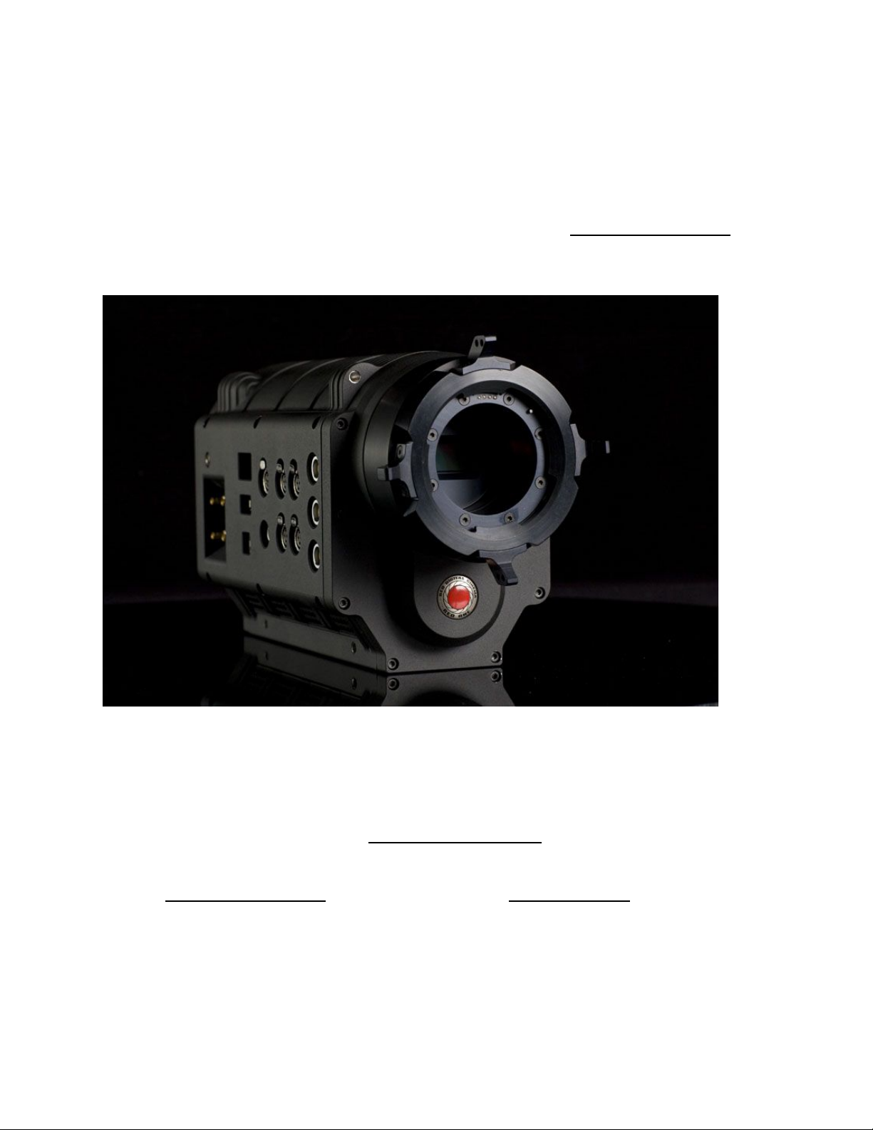
RED ONE Digital Cinema Camera
The RED ONE camera ships as standard with a PL mount. To protect against dust and other
contaminants entering the optical path, ensure that the lens cap is used at all times when a
lens is not mounted on the camera. Additional mounts and adaptors are available for use
with non-PL mount lenses. Please visit www.red.com/contactus for additional information.
Operational hints and information about specific camera applications can be found on our
web site www.red.com/support at the on-line community www.reduser.net.
If you have a technical problem, or receive a camera damaged in shipment, please log on to
our service web site at www.red.com/support or call +1.949.206.7900 for the support team.
Page 3
Feb 07 2008 Copyright RED Digital Cinema
3
A wide range of options and accessories are available to customize your RED ONE camera.
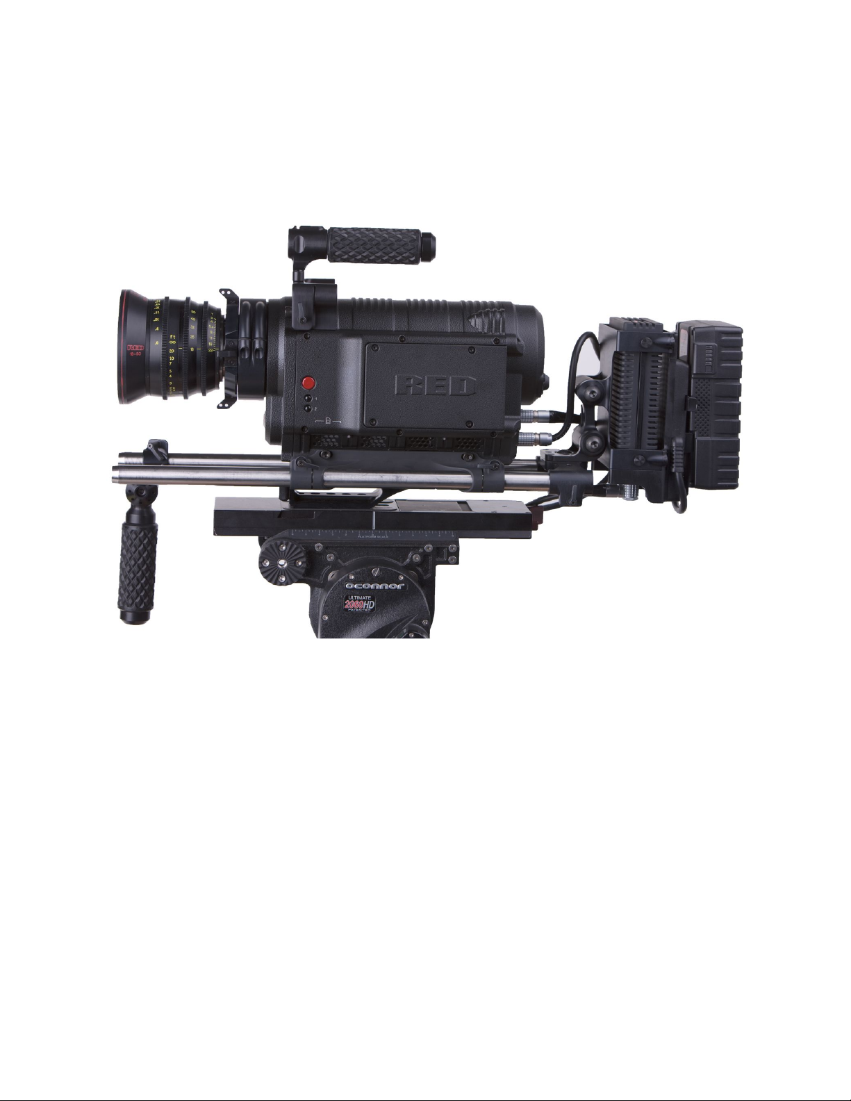
The Basic Production Pack includes a top bracket and top handle, base plate and two 19mm
rods, an adjustable grip handle, a combination shoulder pad/wedge plate adaptor, V mount
battery plate, and a digital magazine cradle.
RED ONE camera with Basic Production Package (battery, RED-DRIVE & lens not included)
The distance from the digital magazine cradle to the camera back may be adjusted to counter
balance the weight of the lens. In addition the shoulder pad/wedge plate adaptor can slide
against the base plate and be locked in position. The adaptor includes wedge plate mounting
holes, so there is no need to remove this component between on-the shoulder and tripod applications. Additional rods, brackets and grips may be added to the Basic Production Pack to
configure the camera to a wide variety of studio and field production applications.
The RED ONE Power Pack includes two 140Wh batteries, RED CHARGER and an auxiliary
power cable. When connected to a 120V/240V AC power source, the charger sequentially
fast charges two batteries, or supplies the camera with 100W @13.8V regulated DC power.
Page 4
Copyright RED Digital Cinema Feb 07 2008
4
2. Ca mera Asse mbly
The RED RAIL BASE PLATE, TOP BRACKET, and HANDLES are attached to the camera body
using ! - 20 hex screws. A HEX driver is supplied with the camera. The rails and shoulder
pad/wedge plate adapter slide into the base plate. The RED CRADLE, which holds a RED
DRIVE and the V mount battery plate, attaches to the Universal Rail mount plate using a hex
screw. This is mounted to the camera using 19mm rods.
If using RED-DRIVE, plate it into the RED-CRADLE and secure it with the four thumbscrews. Then
connect the RED e-SATA cable to the RED-DRIVE and to the e-SATA input on the rear of the
camera body. Connect the power cable from the battery plate adapter to the DC input on the
rear of the camera body.
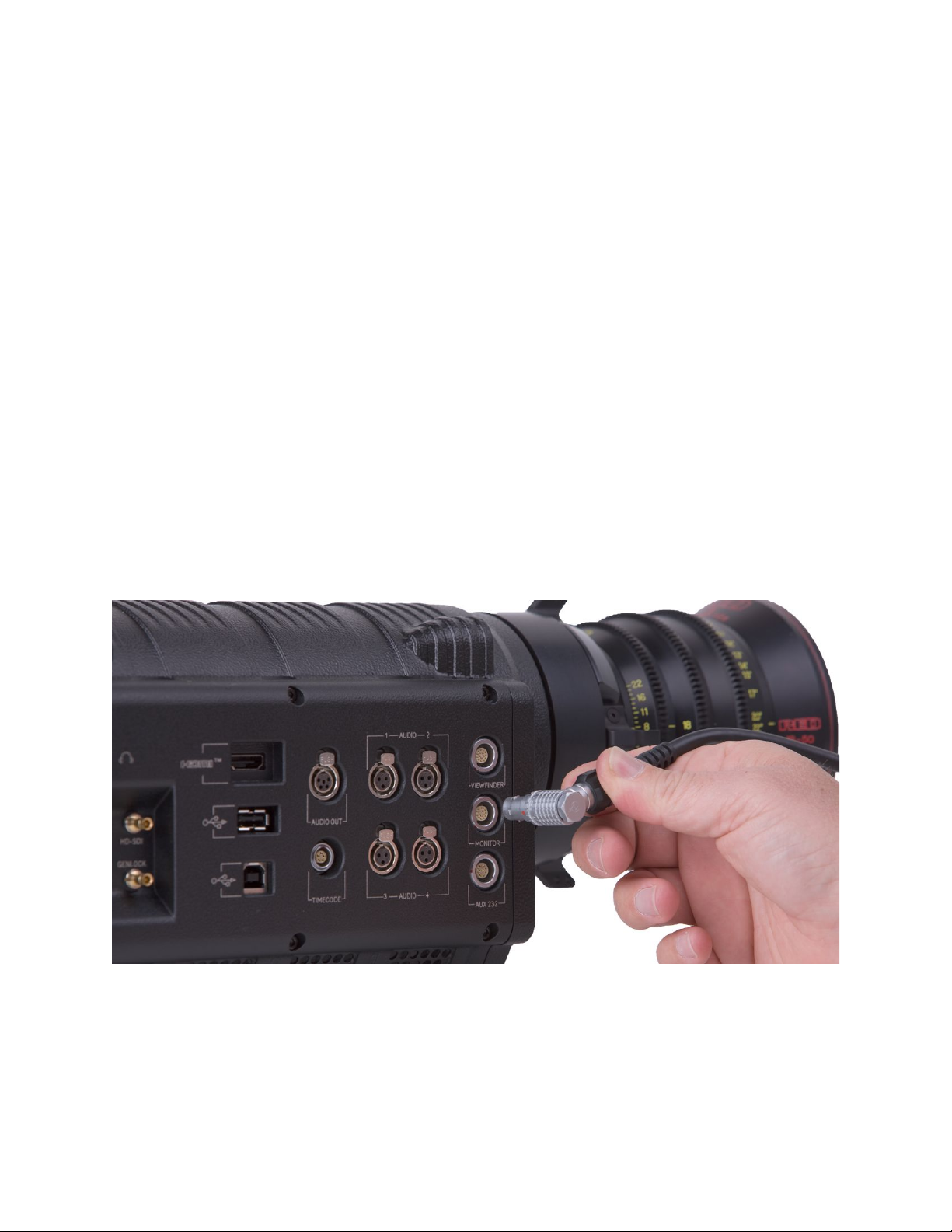
The RED-LCD and RED--EVF viewfinder are mounted to the camera body using a RED ARM. Attach the RED ARM to the camera body using the shorter threaded screw. There are attachment
points on the camera body or on the RED RAIL TOP BRACKET. Attach the other threaded end
of the arm to the RED-LCD or RED-EVF.
Then connect the cable from the camera body to the RED-LCD or RED-EVF. Carefully align the
red dots on the socket and plug, and push firmly to establish contact.
Attaching the RED-LCD or RED-EVF
The RED-LCD and RED-EVF cables are interchangeable; but the outputs are not. The RED-EVF
should be connected to the upper output; a RED-LCD should be connected to the lower output.
Page 5
Feb 07 2008 Copyright RED Digital Cinema
5
Remove the lens cap and mount the PL lens you wish to use. The lens will have four metal tabs
with cutouts for the registration pin in the mount. If using S4/i compatible lenses the data pins
should be at the top of the lens.
Note : Mat chi ng pins a re not curr ently ins talled in the R ED P/L mount.
Attach matte box and motors, and any auxiliary power cables required to power these items.
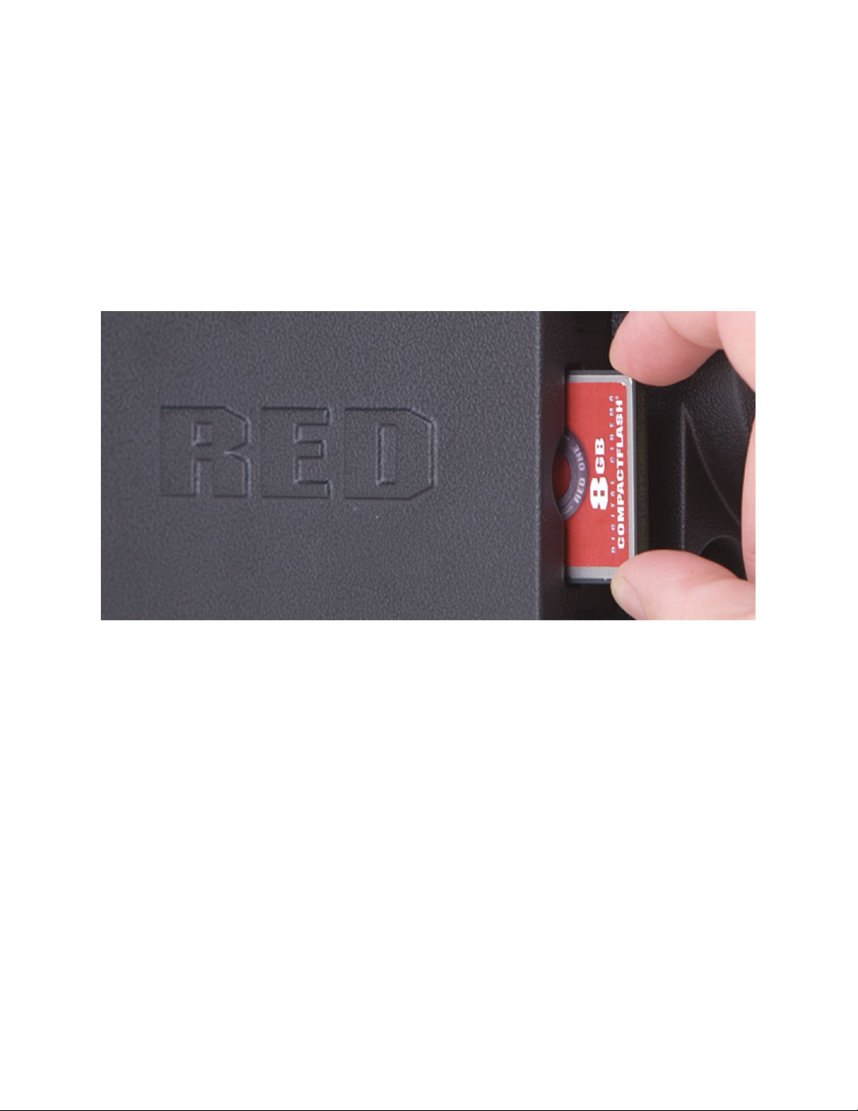
Insert the digital media, such as RED 8GB compact flash (CF) card, or connect a RED-DRIVE via
the supplied custom e-SATA cable.
Inserting a Compact Flash card
Attach a RED-BRICK 140 battery, or connect to a RED-CHARGER using the supplied cable.
Now adjust the balance of the camera. The RED CRADLE/Universal Rail mount unit slides on
19mm rods so you can adjust the distance to the camera back. Find the position that best offsets
the weight of the lens. Finally tighten the butterfly locks to maintain that position. The shoulder
pad/wedge plate adaptor is also designed to slide within the RED RAIL base plate until you
lock it in place. You don’t need to remove it to mount the camera on a tripod.
Press the On/Off switch to power the camera. The rear status display will illuminate, and after
approximately 60 seconds it will display the camera PIN, firmware build and firmware version.
The P.I.N: is a unique product identification code in the format ABC_123_XYZ. This code is included in the metadata recorded with each image. The PIN provides tracking data for customer
service and assistance in authenticating legal ownership of the camera.
When the camera is ready for use, the lower LED to the right of the status display turns green.
Page 6
Copyright RED Digital Cinema Feb 07 2008
6
3. Physi cal Co ntrol s
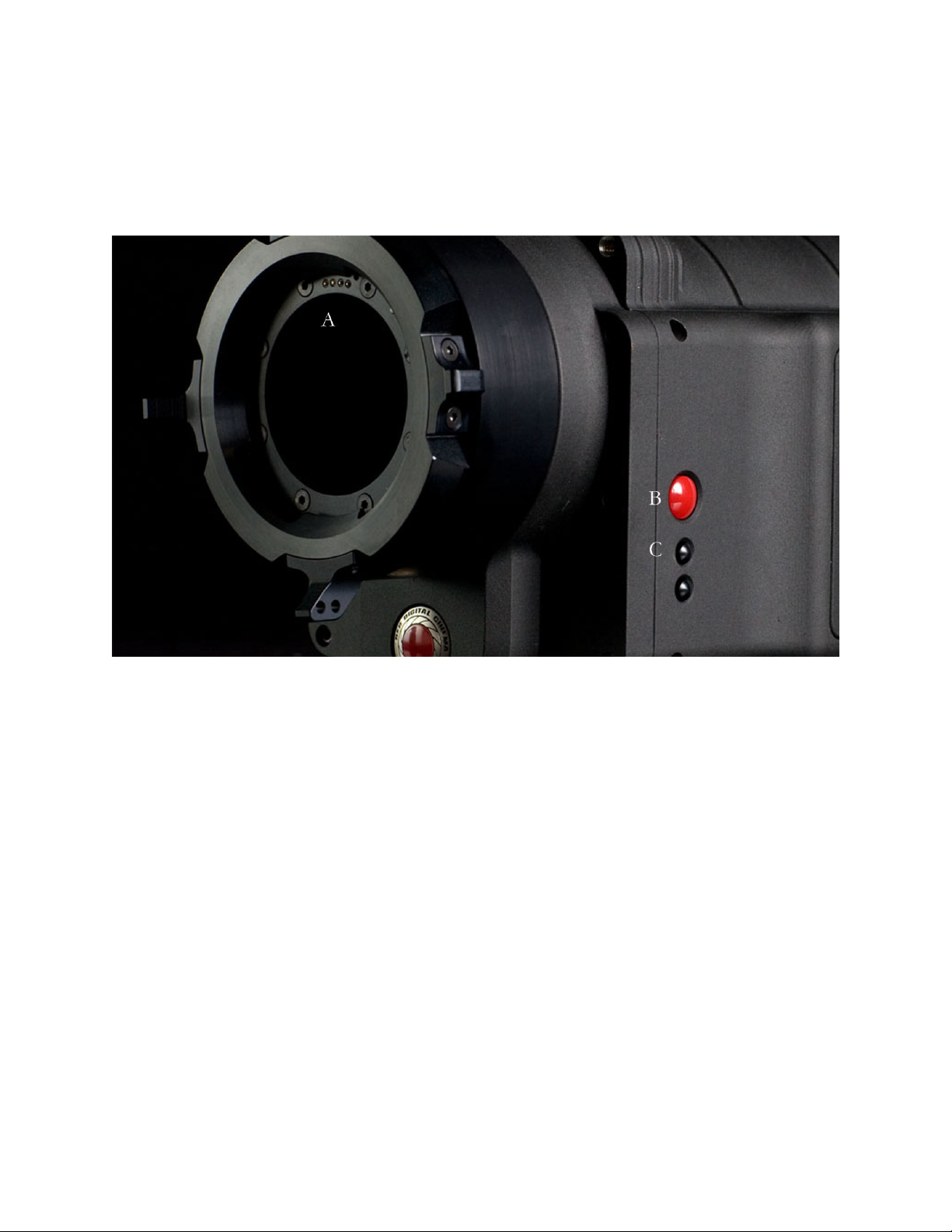
This section describes the physical controls on the RED ONE camera body.
A. PL Lens Mount B. Record C. User Keys 1 and 2
A PL mount is provided as standard with the RED ONE camera. The mount is compatible with
the majority of S35mm, 35mm and S16mm cinematography lenses; and with B4 lenses via
the optional B4 to PL converter. The PL mount may include an S4/i interface. If installed, this
interface permits the camera to communicate with various lenses from RED Digital Cinema,
Cooke Optics. Ltd and other lens manufacturers supporting the S4/i protocols.
On the left side of the camera body are a RECORD key and two User Keys. The two User Keys
are pre-assigned to AUTO WB and FOCUS checks functions. If desired, these keys may be disabled in the SYSTEM / KEYMAP sub menu to prevent accidental use.
An SD Memory card slot is provided below this group of keys, and may be used for camera
setup storage and software upgrades. A blank 512MB SD card is provided with the camera.
Page 7
Feb 07 2008 Copyright RED Digital Cinema
7
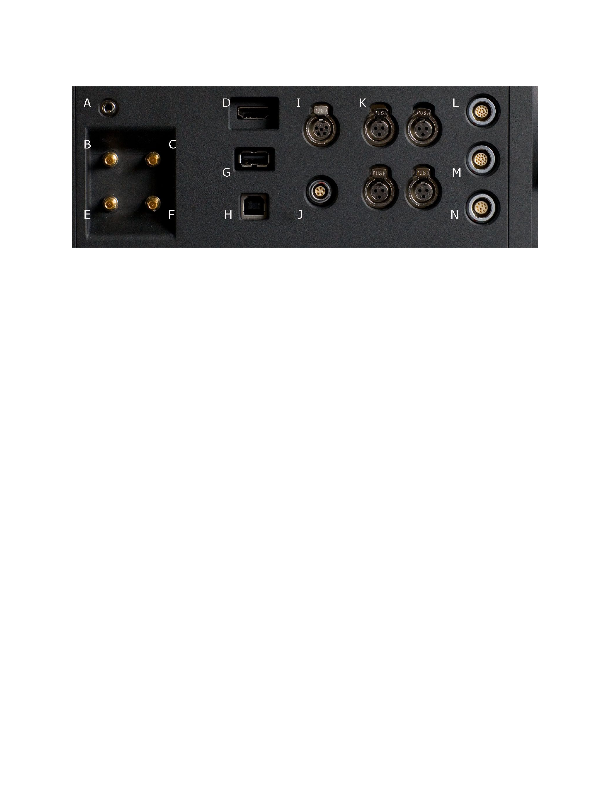
A Headphone B Dual Link HD-SDI (A) C Dual Link HD-SDI (B)
D HDMI Out E Preview HD-SDI F Video Genlock
G USB-2 (peripheral) H USB-2 (computer) I Audio Monitor
J Timecode K Audio Ch 1 – 4 (1-2 Upper Left - Right, 3-4 Lower Left - Right)
L RED-EVF M RED-LCD N Aux / RS232
The right side of the camera contains all the video, audio and time code inputs and outputs.
From top left to bottom right, these comprise a 3.5mm stereo headphone jack, and four DIN
1.0/2.3 video connectors that support dual link HD-SDI, Preview HD-SDI and Video Genlock.
Next an HDMI output, a USB-2 type A port for USB peripherals, and a USB-2 type B port to
connect the camera to a computer, a 5-pin mini-XLR stereo audio output and 5-pin LEMO
timecode input/output. Four three-pin mini-XLR audio inputs make up the next group. Finally
there are three LEMO connectors that provide video and power for the RED-EVF and REDLCD, and an Aux/RS232 port that can interface to a variety of lens motors or controllers.
A 6-inch length DIN 1.0 / 2.3 to BNC video adaptor cable and an 9 inch length mini-XLR to
mini-XLR cable and XLR to mini-XLR adaptor are provided with the camera. Additional cables
and adaptors may be ordered from the on-line store at this address www.red.com/store
Page 8
Copyright RED Digital Cinema Feb 07 2008
8
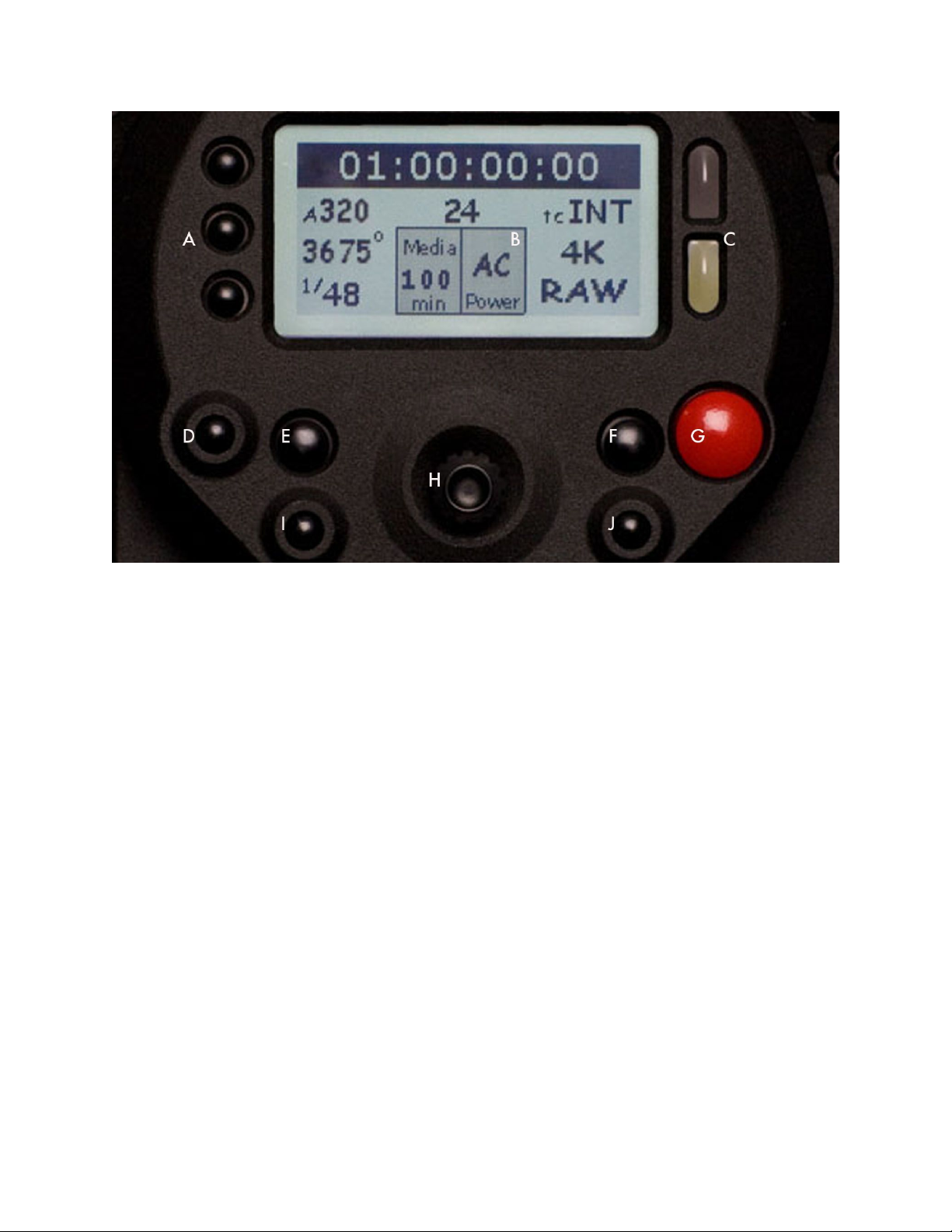
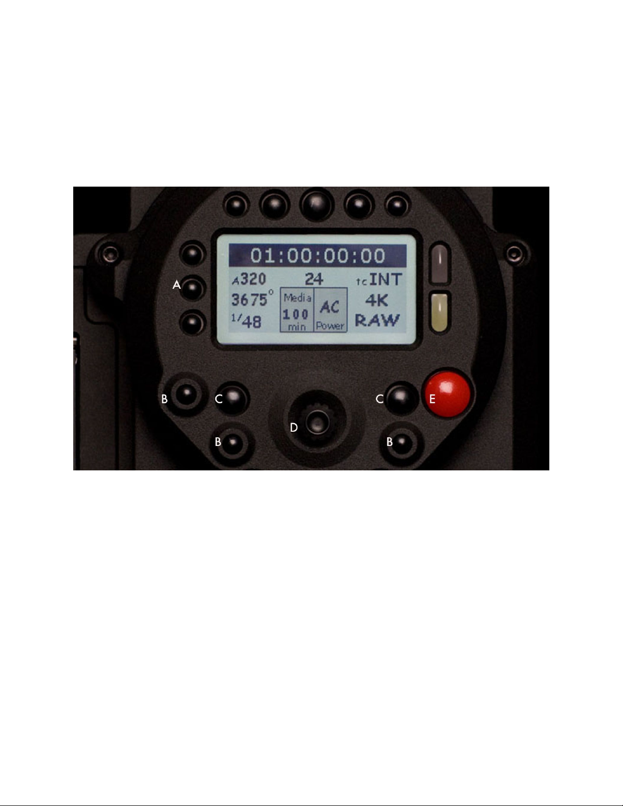
A User Menu A. B. C B Status Display C Tally & Ready Lamp
D Sensor Menu Key E EXIT Key F UNDO key
G Record Start / Stop H Joystick I A/V Menu Key
J System Menu Key
On the rear of the camera, several buttons surround a daylight readable status display.
To the left of the status display are three Quick Menu buttons, A, B and C, which directly access
Exposure, Shutter Speed and Color Temp (White Balance) menus. Below the status display are
the Joystick, Sensor Menu, Video Menu, System menu, Exit, Undo and RECORD buttons.
The status display reports key camera status values, and is complimented by two LED’s: the red
LED provides a record tally, while the green LED indicates the camera is ready for operation.
The five buttons above the display are used for playback control. From left to right, the keys are
Clip Start / Previous Clip, Play Reverse, Clip Play/Pause, Fast Fwd and Clip End / Next Clip.
Page 9
Feb 07 2008 Copyright RED Digital Cinema
9
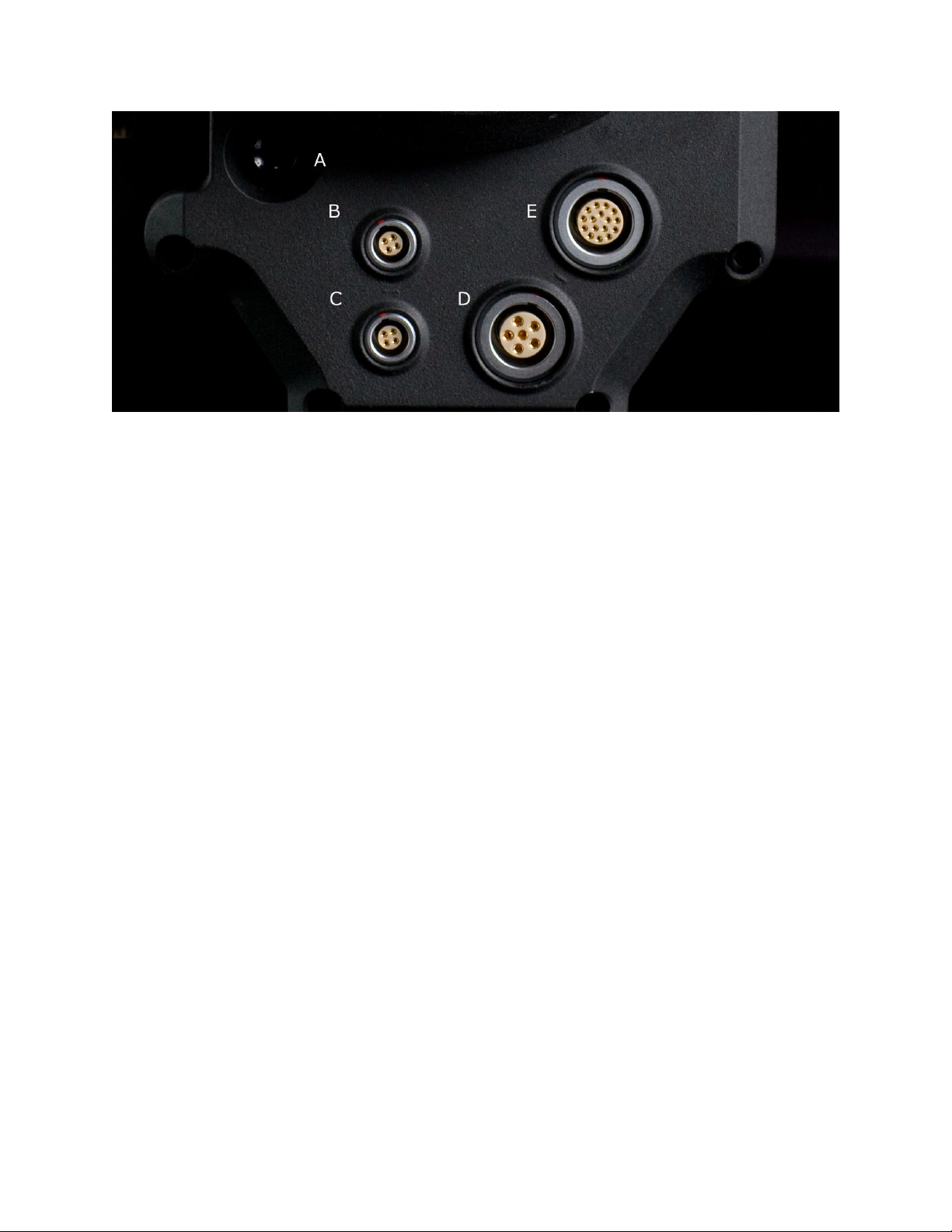
A Power On/Off switch B Aux Power / GPIO A
C Aux Power / GPIO B D Camera 11.5 - 17V D.C Input
E e-SATA Interface (to RED-DRIVE or RED-RAM magazine)
Underneath the status display key group are the Power On/Off switch (top left) two 4 pin Auxiliary Power /GPIO outputs, 6 pin camera system POWER input and a 16 pin DRIVE interface.
Each Auxiliary Power / GPIO connector can supply 1.75 amps of unregulated 11.5 – 17V DC
power to accessories such as range finders or compact lens motors. In addition, the upper connector provides a GPI trigger for Record Start / Stop and an In-Record tally output. The lower
connector provides a GPI trigger for Single Frame Record and a Frame Recorded tally output.
The DRIVE interface utilizes standard e-SATA protocols, and supplies power and data to record
REDCODE RAW compressed video data plus audio to RED-DRIVE or RED-RAM digital media.
To power the camera up from a RED BRICK battery, press the power on/off switch once.
To power the camera up from a RED-CHARGER, connect it via the supplied power cable. Plug
the RED-CHARGER into an AC power source and switch it on. After the green LED illuminates
on the RED-CHARGER, the camera can be powered on by pressing its On/Off switch.
To power the camera down, press the power on/off switch once.
Note : After po wer down, is re co mme nded t hat y ou w ai t 5 seconds a fte r the
camera ’s green s ta tus LE D go es o ff be fore p ow ering the camera u p a ga in.
Page 10

Copyright RED Digital Cinema Feb 07 2008
10
4. Theory of Operation
The RED ONE Digital Cinema camera provides high performance digital imaging over a wide
range of frame rates and optical formats including Super 35mm, 35mm and Super16mm. The
camera is supplied as standard with a PL mount, and may be configured with 19 mm rods to
accommodate most cinematography lenses, matte boxes and follow focus systems. Adaptors
for 15mm offset studio and 15mm lightweight rods are also available.
In addition to compatibility with existing PL mount cinematography lenses; a select range of
S35/35mm format PL mount prime and zoom lenses are available from RED Digital Cinema.
Other lens mounts, including Canon FD, and Nikon F will be available from RED and 3rd parties, permitting the use of Nikkor and Canon photographic lenses. To use these mounts the PL
mount must be removed. This should be done in a dust-free environment, as the camera’s optical path will be exposed to the elements.
A B4 mount to PL mount adaptor is also available to permit use of 2/3” HD lenses on the RED
ONE camera. The optical coverage is provided is equivalent to S16 mm. Hence, the maximum
recording resolution with these lenses will be 2K RAW.
Mysteri um™ Sens or
The Mysterium™ sensor has been specifically designed for use with the RED ONE camera,
and provides variable frame rate imaging over 1- 60fps (1-120fps in 2K windowed mode).
Mysterium is color balanced for 5,000 degrees Kelvin, but may be electronically compensated for operation at any color temperature in the range 1,700 to 10,000 Kelvin. White
Balance presets at 3200K and 5600K are available for Tungsten and Daylight lighting.
Mysterium includes an integrated 12bit resolution analog to digital converter for each pixel,
and is capable of delivering up to 66dB dynamic range (11 stops) when operating at the default Exposure Index of 320 ASA.
Image Pro cessi ng
The data received from the Mysterium sensor is formatted as unprocessed 12 bit RAW data,
(pixel defect corrected but not color processed) a technique common to digital photography.
RAW data may be recorded in-camera using wavelet based compression (REDCODE RAW)
to compact flash, hard disk drive or flash drive media.
The RAW output data of the sensor is also converted to white balanced RGB 4:4:4 monitor
video that conforms to the SMPTE/EBU REC709 color gamut. It may be lightly color processed to illustrate a “look”, and feeds the RED-EVF, RED-LCD, HD-SDI and HDMI outputs.
Page 11

Feb 07 2008 Copyright RED Digital Cinema
11
Audio Pro ce ssi ng
Line input analog audio received via the min-XLR inputs is immediately digitized at 24 bit per
sample at a 48KHz sample rate. Microphone level audio inputs are routed via an adjustable
gain pre-amplifier before digitization, no gain adjustment is available for Line level inputs.
Reference Line Input level (0dB) is 0.775v. Microphones with an output sensitivity ranging
between -30dB and -60dB can be accommodated by the pre-amplifier, which provides user
adjustable amplification over the range of +22dB to +54dB with minimal signal degradation.
Due to the significantly higher precision and dynamic range of 24 bit sampling, input stage
limiters or AGC’s are not provided by the RED-ONE camera. Th e digi ti zed audi o dat a
can be co nsider ed a s hig h dyna mic range RA W sound info rma ti on t ha t is compli me ntar y to t he h igh dyna mic ra nge R AW vi deo informat ion.
Just as linear response RAW video data is converted to REC 709 for metering, the linear response audio data is converted to Log Base 10 data for metering. A color coded 4 channel
audio meter is provided in the lower section of the camera GUI. This information is visible in
the RED-EVF, RED-LCD and HDMI (DVI) monitor outputs.
The goal for optimal quality recording is to place the audio reference level at an appropriate
location in the digital range, providing sufficient headroom above the reference level to prevent clipping, while maintaining the sound quality of lower volume sources such as dialog.
A 0dB reference voltage level of 0.775V provides approximately 8dB of headroom above
reference. Microphone pre-amplifier gains should be adjusted accordingly (i.e. 8dB lower)
e.g . With an Azde n SGM X 1 m icrop ho ne r ated at - 41d B sensit ivit y, s et t he mi crop hone pre- ampli fi er to (4 1 – 9 ) = 3 2d B for o pti ma l recorded sig nal qual it y.
Monitori ng Outp uts
The RED ONE camera supports a variety of monitoring options.
RED-EVF: 1280 x 848 resolution RGB 4:4:4 progressive video display with Surround View,
frame guides and safe action / title overlays, zebra and false color exposure overlays, waveforms, camera status and operation menus.
RED-LCD: 1024 x 600 resolution RGB 4:4:4 progressive video display with Surround View,
frame guides and safe action / title overlays, zebra and false color exposure overlays, waveforms, camera status and operation menus.
Page 12

Copyright RED Digital Cinema Feb 07 2008
12
HDMI (DVI): 1280 x 848 resolution 4:2:2 video output with Surround View, frame guides
and safe action / title overlays, waveforms, and camera status and operation menus on the
HDMI port. This signal is compatible with most DVI equipped SXGA computer monitors. *
PREVIEW (720p) 1280 x 720 resolution 4:2:2 video output (720p 50.00 or 720p 59.94 Hz)
with Surround View, frame guides and safe action / title overlays on HDMI and HD-SDI ports.
EVF+PVW: Provides both a full 1280 x 848 resolution RGB 4:4:4 progressive display to the
RED-EVF and a1280 x 720 resolution 4:2:2 video output to the HDMI and HD-SDI ports.
Note: Only one monitor choices can be selected. PREVIEW (720p) is the default. To activate
RED-EVF, RED-LCD, HDMI (DVI) or EVF+PVW options select that monitor output as follows –
Press the SYSTEM menu key, and then push the joystick right to highlight MONITOR.
Press the joystick in, and then push the joystick to the right to highlight ACTIVE
Rotate the joystick to select RED-EVF, RED-LCD, HDMI (DVI) or EVF + PVW as the new active
monitor output.
Press the EXIT key to return to the main camera menu. The monitor setting will be held in
camera memory. Once it is set it will not need to be re-set when power cycling the camera.
*Note: RED has tested Dell 1708FP (1280 x 1024) and the LG L206W (1680 x 1050) PC
monitors with an HDMI to DVI adaptor cable. You should test for PC monitor compatibility.
RED- LCD and R ED- EV F
The optional RED-LCD and RED-EVF are specialized video monitors that may be attached to
the camera body, and provide a variety of tools to assist framing, focus and exposure.
Page 13
Feb 07 2008 Copyright RED Digital Cinema
13
- Surround View, which is an additional visible area outside the actual recorded image.
- Frame guidelines show common film presentation and television formats such as 2.40:1
and 1.85:1, picture center, and/or television aspect ratios such as 16:9, 14:9 and 4:3.
- Focus is aided by the high resolution of the displays and FOCUS check, a 2x image
magnify function, complimented by a selectable waveform based focus assist meter.
- Dual zebra, false color meter and a selection of histograms assist optimal exposure.
System information including instantaneous frame rate, exposure index, shutter speed, color
temperature, recording format, clip name, timecode, battery and media remaining is provided in the LCD/EVF monitor outputs, and the rear status display on the camera back. For
applications when a RED-LCD or RED-EVF are not desired – for example when working on a
crane – the Surround View video, frame guides, and exposure overlays are also available on
the Preview HD-SDI output, for remote camera monitoring up to 200 ft away.
Page 14

Copyright RED Digital Cinema Feb 07 2008
14
Digita l Mag azi nes
REDCODE RAW compressed video, time code and other metadata, may be recorded to onboard or attached digital media devices including -
RED FLASH CF – An internal reader/writer that utilizes high speed Compact Flash media.
RED-DRIVE – A hard disk memory based Digital Magazine of up to 320GB capacity.
RED-RAM – A solid-state flash memory based Digital Magazine of up to 64GB capacity.
Either type of Digital Magazine may be connected to a computer via FireWire or USB-2.
Each clip is recorded with a unique clip name and placed in a clip folder like this -
Rec or d Indica ti on
On record, the RED ONE camera provides a variety of record tallies. Timecode, normally
displayed in white colored text, will turn red, and a small red dot will appear in the top left
corner of the monitor. The upper LED to the right of the status display screen will turn red,
and if using an EVF, the front LED will also turn red.
If media is not present, the camera will provide a warning as follows – RECORDING ERROR
NO_DIGIMAG. If this warning is displayed, check the physical mounting of the CF card, or
that the RED-DRIVE is attached to the e-SATA port using the supplied 16 pin LEMO cable.
Met ad ata
RED-ONE cameras record Metadata, which is data that describes the precise characteristics
of the picture and sound data captured in each frame of footage. This may include camera
specific setup information, project and clip management information, Edge code, Time code,
date and location, lens settings, and video and audio processing information.
Page 15
Feb 07 2008 Copyright RED Digital Cinema
15
Pos t Pr oduct io n
Compressed REDCODE RAW images may be post processed using RED ALERT! or REDCINE
applications. These applications convert RAW sensor data to RGB video, and correct white
balance, exposure, tonal response and color timing. The processed footage may then be exported to a variety of industry standard file formats for use in postproduction.
File Na mi ng Co nven tion s
As each recording is made, the RED ONE camera calculates a Clip Number, starting at clip
001 for each new piece of digital media. The Clip Number and Slate data are combined to
create the Clip Name identifying each recording. In a similar manner, any time digital media
is formatted by the camera, a unique camera ID letter and Reel Number are assigned to that
media. This allows each clip to be uniquely identified, even operating in a multi-camera shoot.
e.g. for each clip, a Clip Name is created using the structure: A001_C001_070828.RDC
Where A = camera A, 001 = reel 001, C001 = clip 001, 07 = 2007 and 0828 = Aug 28.
Three cameras identified as A, B and C can therefore have individually recognizable clips
A001_C001_070828.RDC B001_C001_070828.RDC and C001_C001_070828.RDC
A single camera identified as A can have individually recognizable reel numbers, such as
A001_C001_070828.RDC, A002_C001_070828.RDC, and A003_C001_070828.RDC
Under normal operation, the reel number continues to increment each time a new piece of
digital media is mounted by the camera up to a maximum value of 999. However the reel
number may be manually reset to 001 or other value, for example at the start of each day.
A001_C001_070829.RDC and then force to 1 for A001_C001_070830.RDC
Using the same technique, virtual reels can also be created on a single piece of digital media.
A001_C023_070828.RDC and then force to 5 for A005_C024_070829.RDC
Page 16

Copyright RED Digital Cinema Feb 07 2008
16
Time code
As each recording is made, the RED ONE camera records two independent timecode tracks.
Edge Code is a SMPTE timecode track that always starts at 1.00.00.00 on the first frame of
each piece of digital media. It is a sequential code that is continuous from frame to frame and
also between clips. Edge Code is also equivalent to RUN RECORD on a video camcorder.
Time Code is a SMPTE timecode track that records the camera’s clock, or if operated in Jam
Sync mode, records an externally supplied SMPTE master timecode signal. It is therefore a
sequential code that is continuous from frame to frame, but discontinuous between clips.
When in Varispeed or Timelapse recording modes, the timecode counters are updated at the
same frame rate as the recording. This means valid SMPTE timecode is created without count
jumps that would affect clip playback or editing. If using an external timecode source with
Jam Sync enabled, the clip’s master time reference point is the first frame of the recorded clip.
Powe r co nsumpt ion
The camera draws approximately 70 watts in a typical configuration. A RED BRICK 140Wh
battery will run the camera and typical accessories for about 90 minutes. The camera is normally cooled by passive convection from the camera body, assisted as required by a fan.
When using the RED CHARGER, recharge time for a single RED BRICK battery is 200 minutes.
The battery can also be partially charged, to approximately 80% capacity, in 120 minutes.
Charge times may be significantly longer on other V lock compatible battery chargers.
Oper ating the ca mera fr om the RED-CH ARGER.
Plug the RED-CHARGER into an AC power source between (120 – 240V). Plug one end of the
supplied 6-pin power cable into the Aux power output of the RED CHARGER and the other end
into the D.C power input of the camera. Now turn on the RED-CHARGER.
When the LED above the charger’s Aux power output turns green, you can turn on the camera.
Note: The maximum sustainable power load of the RED-CHARGER is 100W @13.8V. The output of the charger is over current protected, and will shut down if an excess load condition occurs. If the output trips for any reason, remove any external loads from the camera, such as
lights, motors etc, turn off the RED-CHARGER and repeat the above procedure.
Page 17
Feb 07 2008 Copyright RED Digital Cinema
17
5. Basi c Oper ation
This section describes the basic controls of the RED-ONE camera and how to initiate a project.
Con tr ol S yste m and Sta tu s Displa y
Command inputs to the camera are made from the rear status display and associated buttons.
A – Quick Access Access to Exposure, White Balance and Shutter Speed
B – Menu Access Access to Sensor, A/V and System menus
C – Menu Control Menu Off and Undo keys
D - Joystick The joystick is a multi-axis controller to navigate the camera menus.
E - Record Record Stop / Start key
The five buttons above the display are used for playback control. From left to right, the keys are
Clip Start / Previous Clip, Play Reverse, Clip Play/Pause, Fast Fwd and Clip End / Next Clip.
Page 18
Copyright RED Digital Cinema Feb 07 2008
18
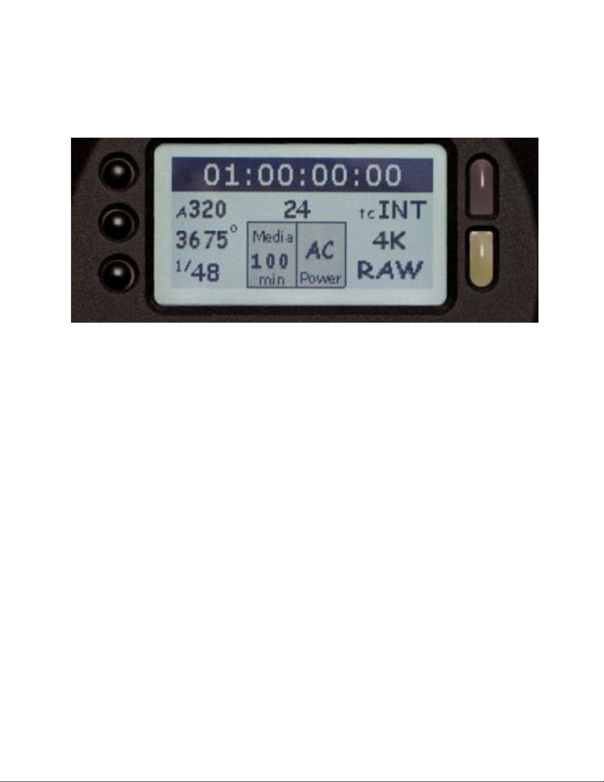
Sta tu s Disp la y
The status display mounted at the rear of the RED ONE camera provides a snapshot of the
camera setup. The elements include –
Timecode / Status reports current timecode value, clip name or system messages*
ASA Value reports current exposure index
Project Frame Rate report the project frame rate, 24.00 fps in this example
Timecode reports timecode lock status
White Balance reports current color temperature
Media reports remaining media capacity in %
Battery reports remaining battery capacity or connection to AC power
Shutter Speed reports current exposure time
Format reports video recording format, 4K in this example
* The timecode value reported may be Edge Code or Time Code as selected by the user.
Page 19
Feb 07 2008 Copyright RED Digital Cinema
19
Sett ing up a pro je ct.
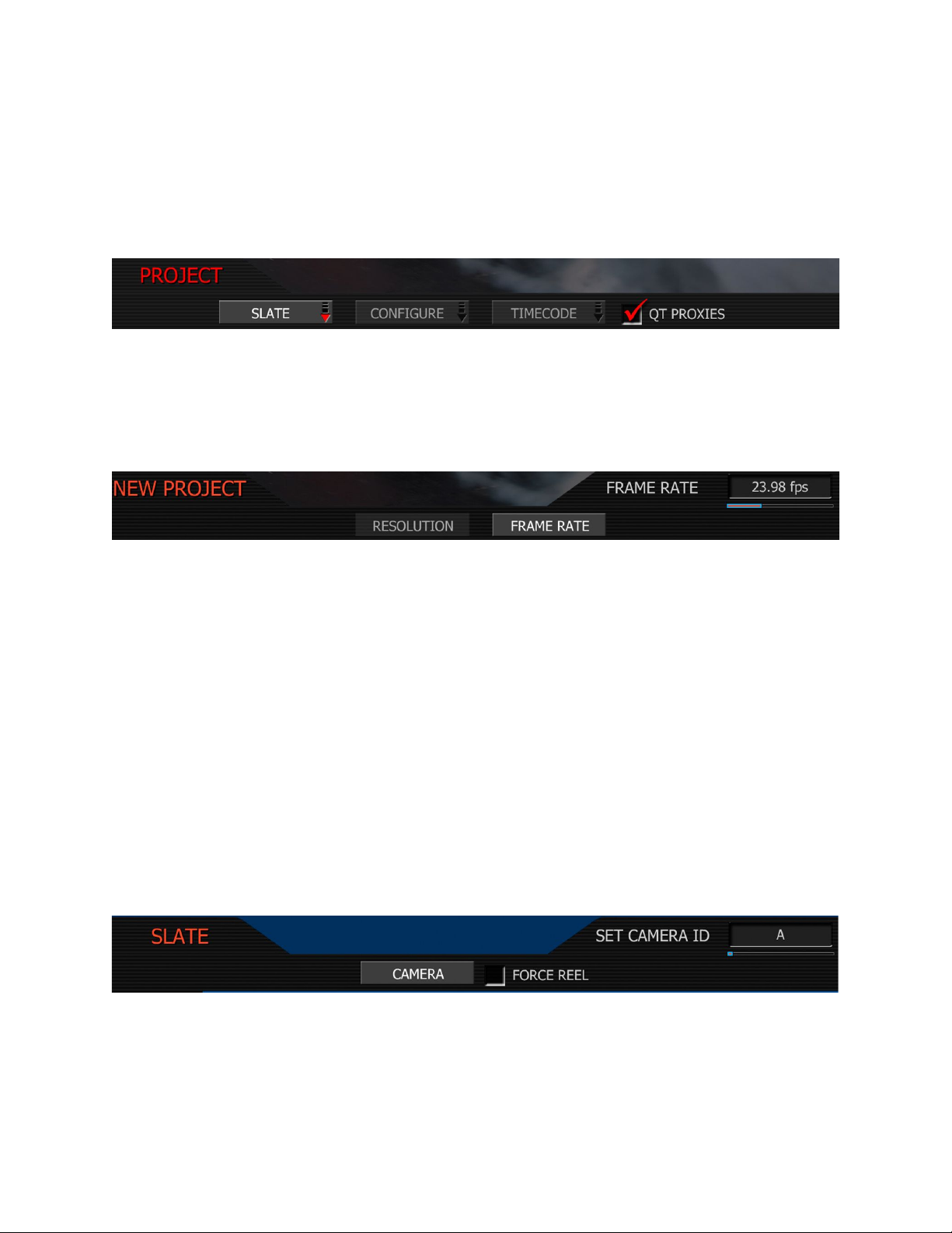
Before recording, the camera must be instructed to follow a Record Quality, Frame Rate and
Resolution. These values are set in the PROJECT sub menu located in the SYSTEM menu.
1. Press the SYSTEM menu key, then the PROJECT key. This highlights the PROJECT sub-menu
2. Push the joystick right, then press to enter the CONFIGURE menu to set the QUALITY
Quali ty. Choose between REDCODE 28 or REDCODE 36. Default is REDCODE 28.
Note: REDCODE 36 limits the available choices of frame rates and resolutions to CF cards.
3. Next select the project FRAME RATE
Fra me Rate: Choose between 23.98, 24.00, 25.00 or 29.97fps Project Frame Rates.
Note: 2K recording resolutions also support 50.00 and 59.94 fps Project Frame Rates.
4. Next select the project RESOLUTION
Reso luti on. Choose 4K, 3K or 2K, or 2:1 variants. Use 2K or 2K 2:1 for S16mm/B4 lenses.
Note: A project can only support one Project Frame Rate as this defines the frame rate to be
used for timecode and for clip playback. It is also the primary frame rate for acquisition, but
variable speed (overcrank and undercrank) recordings can be made above and below this
base frame rate. On playback these recordings will be displayed at the Project Frame Rate
5. Finally, push the joystick left, and press it again to enter the SLATE menu.
- CAMERA Select a letter between A – Z. The default is camera letter is A.
- REEL Select a number between 1 and 999. The default reel number is 1.
After making any adjustments to the SLATE menu, press the EXIT key to exit the menus.
Page 20
Copyright RED Digital Cinema Feb 07 2008
20
Rec or ding
Check that you have a RED-DRIVE attached, or Compact Flash card inserted in the camera.
To initiate a recording, press either RECORD button. Press once to begin recording and again
to stop recording. The camera will automatically create a file name for every clip recorded on
the digital magazine or media.
REDCODE RAW recordings store the Color Temperature and Exposure (ASA) values you enter
as metadata. This metadata is used to color balance the viewfinder and other monitor outputs.
It is also used in REDALERT! as the initial White Balance point – change it if you wish – when
you process the RAW footage. Timecode generated by the camera is Non Drop Frame (NDF).
Digital media should be treated with equal care as exposed film or a videotape master. We
recommend storing digital media that contains your footage in a secure location and backing
up the data on another digital media, such as data tape or a hard disk drive.
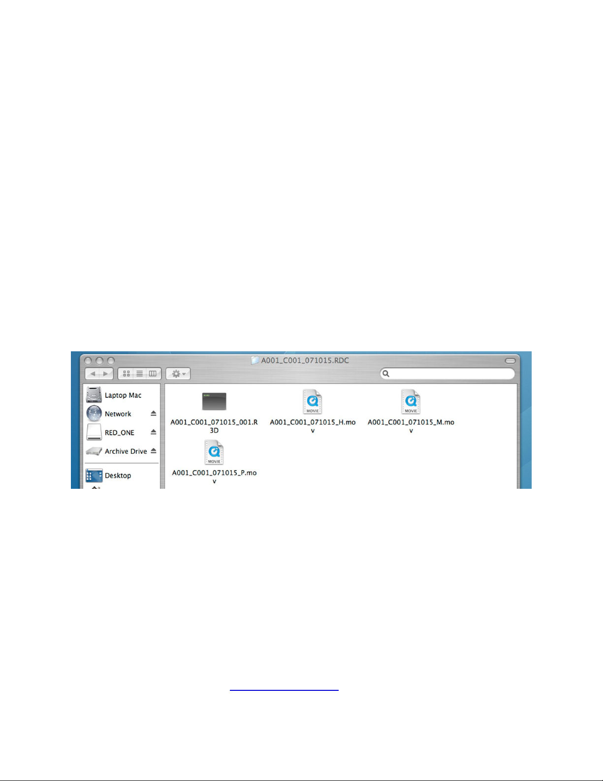
Each clip is recorded to the digital media in a separate folder and with a unique clip name. To
copy the clip from the digital media to a Macintosh or Windows computer, just drag and drop
its folder to the computer’s storage device. If you open the Clip folder, it will look like this –
There will be one or more REDCODE RAW data files (.R3D) containing RAW sensor data,
plus audio and metadata, and three QuickTime reference movies, which allows a QuickTime
Player to display the recorded RAW data at _H high, _M medium or _P proxy resolutions.
Double click on either of the QuickTime reference movies to see a preview of the .R3D file.
Playback frame rate will depend on the processor speed of your computer. If the frame rate is
too low, select a smaller QuickTime movie. Typically the preview resolution will be the best
choice for a battery powered laptop computer or older tower configuration model.
Note: to operate with QuickTime under Macintosh OSX, you must install the supplied REDCODE RAW plug-in available at www.red.com/support QuickTime for Windows is not supported at this time.
Page 21

Feb 07 2008 Copyright RED Digital Cinema
21
Playback
Playback of recorded clips is available on-camera using the Transport Control Keys.
The I> key is used to enter PLAYBACK mode, and to initiate playback of the last recorded Clip.
Press it once to enter Playback mode, and a second time to start playback. Once in clip playback, this key acts as a Play/Pause toggle.
The >> key permits the Clip to be played back at higher speeds. Each press of this key cycles
clip playback between 2 x, 8 x and 32 x speed playback.
The << key permits the Clip to be played back in reverse. Each press of this key cycles clip
playback between – 1 x, - 2 x and - 8 x speed playback.
The I< key cues the Clip to its Start Frame. If already at the Start Frame, pressing this key again
will cue to the Start Frame of the previous clip recorded on the digital media, if one exists.
The >I key cues the Clip to its End Frame. If already at the End Frame, pressing this key again
will cue to the Start Frame of the next clip recorded on the digital media, if one exists.
It is recommended, but not necessary, to exit Playback mode prior to the next recording. To
exit playback mode, press the RECORD key, or press the EXIT key to the left of the joystick.
Note: When in playback, all cursors are disabled and the full screen width is used to display a
clean feed of the recorded video signal. If monitoring EVF+PVW or PVW (720p), the 1280 x
720 pixel video output represents a scaled version of your 4K or 2K recording.
Depending on the capture frame rate, pull down may be added to create a standard 720p
59.94Hz or 50.00 Hz high definition video signal which may be recorded or monitored by a
variety of 3rd party devices using HD-SDI and/or HDMI interfaces.
Note: At this time there is no embedded SMPTE timecode available from the HD-SDI outputs.
Page 22

Copyright RED Digital Cinema Feb 07 2008
22
Monit or ing.
RED-LCD and RED-EVF monitors are factory preset digital displays. There are no saturation,
peaking or contrast adjustments as found on analog monitors for correct color reproduction.
All monitor outputs on the RED ONE camera provide REC 709 standard color and gamma.
Image intensity can be adjusted to compensate for ambient lighting conditions. For the REDLCD, use the Up / Down keys on top of the display. For RED-EVF use the rotary encoder.
To assist with exposure, the RED-EVF, RED-LCD and HDMI and Preview HD-SDI outputs can
display either a dual Zebra pattern or a False Color exposure meter overlaid on the video.
RED- LCD Con tr ols.
The top of the RED-LCD provides two round and two triangular keys. The key on the left is
used to turn the METER (e.g. FOCUS ASSIST) selected in the VIEWFINDER menu On/Off.
The two triangular keys in the center are used to increase or decrease the backlight intensity.
The key on the right is used to switch between 1280 x 848 pixel Video plus Menus and 1280
x 720 pixel Video plus Frame Guide modes. If a RED-LCD is physically connected, but there is
no video displayed, press and hold this button to acquire the monitor feed to the RED-LCD.
RED- EVF Contr ols
The focus ring on the viewfinder may be adjusted for optimal subject focus for your eye. The
available diopter range is +1.5 to -2.0.
Page 23

Feb 07 2008 Copyright RED Digital Cinema
23
The User Key closest to the focus ring selects IMAGE MAGNIFY mode. This magnifies the central region of the subject image in the monitor path, but leaves the record path unaffected.
The upper center User Key turns COLOR TOOLS (monochrome or false color) On/Off and
the lower center User Key turns the METER (e.g. WAVEFORM or FOCUS ASSIST) On/Off.
Press and hold the large rotary switch for two seconds to switch the monitor video output from
any other display, such as the RED-LCD, to the RED-EVF if both are attached at the same time.
The rotary switch may also be used to adjust the viewfinder backlight intensity. Push the
switch once to activate this control. Rotation clockwise decreases the display intensity, counterclockwise increases the display intensity. Push the switch once more to lock in the value.
Using exte rnal HD- SDI or HDMI mo nit or s.
To aid external monitor alignment, the RED-ONE camera provides a range of test signals including SMPTE BARS, Luminance and Chrominance Ramps, and a Chip Chart. Note that the
test signal cannot be recorded; it is provided to align external video recorders or monitors
connected to the camera via the HD-SDI or HDMI ports.
Consult your monitors Operations Manual for instructions on video monitor alignment.
Page 24

Copyright RED Digital Cinema Feb 07 2008
24
6. SENSOR MENU Controls
This section describes how to set sensor specific menu parameters including Exposure, Shutter
Speed, Color Temperature, Varispeed and Timelapse. Press the SENSOR menu key at the
bottom left of the status display or a direct access key on the left of the status display.
Note: When recording RAW, Exposure and Color Temperature values are stored as metadata for use in REDCODE RAW compatible NLE and image processing applications.
The Exposure and Color Temperature values only modify the RED-LCD, RED-EVF, Preview HDSDI and HDMI monitor outputs. They do not affect the recorded REDCODE RAW video data.
Exp os ure
Exp os ure Inde x: adjusts the camera’s operating sensitivity. The default exposure index is
ASA 320, adjustable in 1/3rd stop increments from ASA 100 to ASA 2000. If the exposure
index is adjusted, camera metadata logs the change and the monitor path reacts accordingly.
Color Temp erat ur e
Color Temp erat ur e: adjusts the purity of white reproduction of the RGB monitoring paths
at different Color Temperatures of ambient light. Factory default is 5,000 degrees Kelvin.
Preset values are available for Tungsten (3,200K) and Daylight (5,600K). The operator may
also manually set any other Color Temperature in the range 1,700 to 10,000 degrees Kelvin.
The Automatic White Balance function allows the camera to calculate a Color Temperature
that will render a white object as white. AWB mode analyzes the central 25% of the image
visible in the monitor. To use Auto WB, place a white or gray object under the ambient light,
select the Auto WB parameter and then press the Joystick once. If AWB has been assigned,
via USER KEY menu selection, you may also press User B key on the camera side panel.
Page 25

Feb 07 2008 Copyright RED Digital Cinema
25
Tint
Color Temperature calculations assume a pure light source that may not be true in the specific
scene the camera is imaging. To compensate for any residual colorcast, the TINT parameter
can adjust the RGB color balance with a compensating Magenta - Green color component.
Note : Pr essi ng Au to WB cal culat es a new Ti nt val ue . T his i s ma inta ined if the
Color Temp is a djust ed via the Ma nual WB pa ramet er. If you s ele ct t he T ungste n or Dayl ig ht pr es ets, Tin t will b e re set to zero, which i s the de fault val ue .
Shu tter Me nu
Adjusts the exposure time of each frame captured by the Mysterium sensor. The exposure
time is may be programmed via a series of preset Shutter Speeds encompassing all the common shutter angles available on a camera operating at a nominal 24 or 25 fps. Adjustments
may be made to a preset shutter speed by the RELATIVE and SYNCRO parameters.
Ge nlo ck: permits Shutter Phase (scan start time) to be referenced to an external Tri-Level
Sync genlock signal. For 3D and multi-camera applications this permits the precise scan timing
and phase relationship of two or more cameras to be matched.
Mod e: enables one of three following shutter modes. Default is Normal.
Normal: Shutter Speed is defined exclusively by the Shutter Speed setting.
Syncro: Shutter Speed is defined by Shutter Speed, but modified by Syncro setting.
Relative: Shutter Speed is defined by Shutter Speed, but modified by the capture fps.
Page 26

Copyright RED Digital Cinema Feb 07 2008
26
Shu tter Spe ed
When operating in the default (Nor mal ) mode, the Shu tter Speed values are absolute and
independent of the capture frame rate.
This means as Shutter Speed decreases, more light falls on the sensor, increasing exposure
and motion blur on any objects moving within the frame. As Shutter Speed increases less light
falls on the sensor, decreasing exposure and motion blur on objects moving within the frame.
Spee d: Exposure times presets include: 1/24, 1/25, 1/30, 1/32, 1/33, 1/40, 1/48, 1/50,
1/60, 1/96, 1/100, 1/120, 1/125, 1/192, 1/200, 1/250, 1/384, 1/400, 1/500, 1/696,
1/800, 1/1,000, 1/1,200, 1/2,000th sec.
When operating at 23.98 or 24.00fps, these equal common shutter angles of
1/32nd 270 deg 1/96 90
1/48 180 1/192 45
1/60 144 1/384 22.5
Rela tive : When operating in this mode, the Shutter Speed values are proportionately reduced or extended to correspond to changes in the instantaneous capture frame rate. This
mode is analogous to use of a fixed shutter angle on a film camera.
e.g. Enabling Relative mode with 1/48th sec shutter at 24fps will mean 1/96th sec for 48fps,
and 1/16th sec for 8fps. This achieves the same visual result as setting a180 degree shutter.
Syn cr o: When operating in this mode, the Shutter Speed values may be proportionately reduced or extended to tune exposure time to a precise value. Range 10 – 90. Default 50.
e.g. Setting Syncro to 53 with a 1/60th sec shutter is equal to 1/56.6 sec exposure time.
Phase: provides a delay relative to the start of the frame for the exposure time. Phase may
be adjusted over the range - 45 to + 45 degrees. Default value is 0.
Note : T o Con ve rt Sh utter Spe ed t o Angle Equi valent
Equivalent Degrees = (Shutter Speed x Project Frame Rate x 360)
e.g. = 1/48 x 24 x 360) = (8640 / 48) = 180
Page 27

Feb 07 2008 Copyright RED Digital Cinema
27
Shutter Degrees Shutter Degrees
1/32 270 1/120 72
1/48 180 1/192 45
1/50 172.8 1/348 22.5
1/60 144 1/696 11
1/96 90 1/1000 8.6
Note : T o Con ve rt an Angle t o a n Eq uiva lent Shutt er S peed
Equivalent Shutter = 1 / ( Project Frame Rate x 360 / Angle )
e.g. = 1/ (24 x 360 / 180 ) = (8640 / 180) = 1 / 48
Degrees Shutter Degrees Shutter
270 1/32 72 1/120
180 1/48 45 1/192
172.8 1/50 22.5 1/348
144 1/60 11 1/696
90 1/96 8.6 1/1000
Vari spee d
The Varispeed menu supports Variable Frame Rate recording at speeds faster or slower than
the Project Frame Rate and Frame Rate Ramping. VariSpeed recordings can be initiated by
pressing the Record key, or by GPI trigger.
Note : I n al l Var ispeed mode s, audio re cor di ng is disa bl ed.
Page 28

Copyright RED Digital Cinema Feb 07 2008
28
Note: In Varispeed modes timecode is written to digital media at a rate equal to the
instantaneous capture rate. This ensures that the recorded REDCODE RAW data has
valid and sequentially incrementing timecode for use by non-linear editing devices.
Note: In Varispeed, the frame rate display turns yellow, the audio panel reports VARISPEED.
Vari spee d: Before recording, enable this function by checking the Va ri spee d checkbox.
Ramp: enables a speed ramp; a transition over Time from the F rame Rat e to an End Rate
On- Re cord : The ramp will immediately start transitioning from Frame Rate to the End Rate.
On- Even t: On record, the capture frame rate starts out at the Frame Rate, and the start of
the transition to the End Rate occurs only when an external GPI trigger has been received.
Fra merate : enables the user to choose any single frame rate. Minimum frame rate is 1 fps;
maximum frame rate is a function of REDCODE setting, record resolution and media type:
REDCODE 28 RED-FLASH RED-DRIVE
2K 2:1 75 fps 75 fps
2K 75 fps 75 fps
3K 2:1 50 fps 60 fps
3K 36 fps 50 fps
4K 2:1 25 fps 30 fps
4K 25 fps 30 fps
Page 29

Feb 07 2008 Copyright RED Digital Cinema
29
REDCODE 36 RED-FLASH RED-DRIVE
2K 2:1 75 fps 75 fps
2K 75 fps 75 fps
3K 2:1 36 fps 50 fps
3K 30 fps 36 fps
4K 2:1 25 fps 25 fps
4K n /a 25 fps
Time : When Ramp is enabled, this value specifies the transition time to be used by the camera between the (start) Frame Rate and the End (frame) Rate. Default value is 5 seconds.
End R ate: When Ramp is enabled, this value specifies the final (ending) speed of the ramp
in frames per second. When a ramp transition has been completed, the camera will continue
to record at the End Rate until the end of the Recording.
Note: When in Varispeed modes the camera maintains the last exposure time selected (unless
the requested frame rate requires a shorter exposure time) to provide a constant exposure. If
a variable exposure is required set the Shutter Mode to Relative - this is a fixed angle setting.
Time lap se
The Timelapse menu supports single frame image capture and step frame recording under the
control of an internal Intervalometer, side RECORD key or an external (GPI) trigger.
Enable: After making any adjustments in the timelase menu, check the Enable box to enter
these values and enable the Timelapse record mode. The UI indicates by changing the top left
frame rate display from f ps to TL, and the lower right audio level display to TIMELA PSE.
Page 30

Copyright RED Digital Cinema Feb 07 2008
30
Trig ger Mod e: Specifies if the camera is to use a fixed Interval of time or wait for a side
record command or external GPI contact closure to initiate the next frame capture.
Inte rval : the camera waits for the period of time defined by the I nt erva l parameter.
One-S hot: the camera to waits for a side record command or external GPI contact closure.
The default setting is One-Shot.
Spee d: Specifies the shutter speed to be used during Timelapse. This control is the same as is
available in the S hutter menu, but it provides access to additional shutter speeds that may be
used in Timelapse recording.
The additional exposure time presets are 1, 1/2, 1/3 1/4, 1/6, 1/8, 1/12, 1/16 second
Note : I n Build 14 shutte r sp eeds below 1/1 6th se c are not yet implemen ted..
Step Pri nt: Specifies the number of times each single frame captured in timelapse mode is to
be recorded to the digital media. Available range is 1 - 10 frames. Default value is 1 frame.
Inte rval : Specifies the number of seconds the camera will wait before the next image is captured. Range is 1 – 1024 seconds. Default setting is 5 seconds.
Note: When recording in Timelapse mode, the RECORD tally lamp will remain illuminated.
Each successive step print uses the next available Edge Code and Time Code value and uses
the existing clip name. This results in a complete timelapse sequence with a single clip name
and correct timecode sequence.
To exit Timelapse mode press the RECORD button.
Page 31

Feb 07 2008 Copyright RED Digital Cinema
31
7. AU DIO / VID EO MENU Contr ols
This section describes monitor path parameters such as viewfinder, and RGB color and gains.
These parameters are accessed from the VIDEO menu access key.
Available sub menus include VIDEO, VIEWFINDER, AUDIO and HEADPHONE
Vid eo Me nu
Note: The RGB Color and Gain values used by the monitor path are stored as metadata for
use in REDCODE RAW compatible NLE and image processing applications. They can be used
to visualize a specific color “look” but they do not affect the REDCODE RAW data recorded.
Color s ub menu:
The Color sub-menu selects various image processing parameters that may be applied to the
monitor path. They do not affect the actual REDCODE RAW data being recorded.
Saturation: adjusts color saturation. Range is 0.0 (monochrome) to + 2.0 (super color)
Exposure: adjusts image exposure. Available exposure range is ASA 100 to ASA 2000
Brightness: adjusts brightness without crushing highlights. Available range is – 10 to + 10
Contrast: adjusts the overall contrast of the image. Range is -1.0 (flat) to +1.0 (max contrast)
Page 32

Copyright RED Digital Cinema Feb 07 2008
32
Gai n sub- me nu
The Gain sub-menu selects various image processing parameters that may be applied to the
monitor path. They do not affect the actual REDCODE RAW data being recorded.
Red Gain: adjusts the gain of the RED channel only. Range is 0.0 (no Red) to +4.0
Blue Gain: adjusts the gain of the BLUE channel only. Range is 0.0 (no Blue) to +4.0
Green Gain: adjusts the gain of the GREEN channel only. Range is 0.0 (no Green) to +4.0
Vie wfind er Menu
This menu permits the operator to adjust operation of the viewfinder.
Color : When checked, forces the RED-EVF and RED-LCD outputs to monochrome or a false
color exposure assist or Edge Highlight ( this is not f ully o pe ratio na l in Bu ild 1 4)
In Mo no chro me, the color component of the image is removed.
In Fal se Co lo r the color component of the image is replaced by an overlay of colored
bands representing the exposure levels with the image. Bluer colors represent underexposed
areas, green is 18% ND, yellow and red colors represent more exposed areas.
This chart illustrates the color mapping relative to stops of exposure and 0 - 108 IRE values.
Note the green and pink bars that allow quick exposure setup for 18% ND and skin tones.
Page 33

Feb 07 2008 Copyright RED Digital Cinema
33
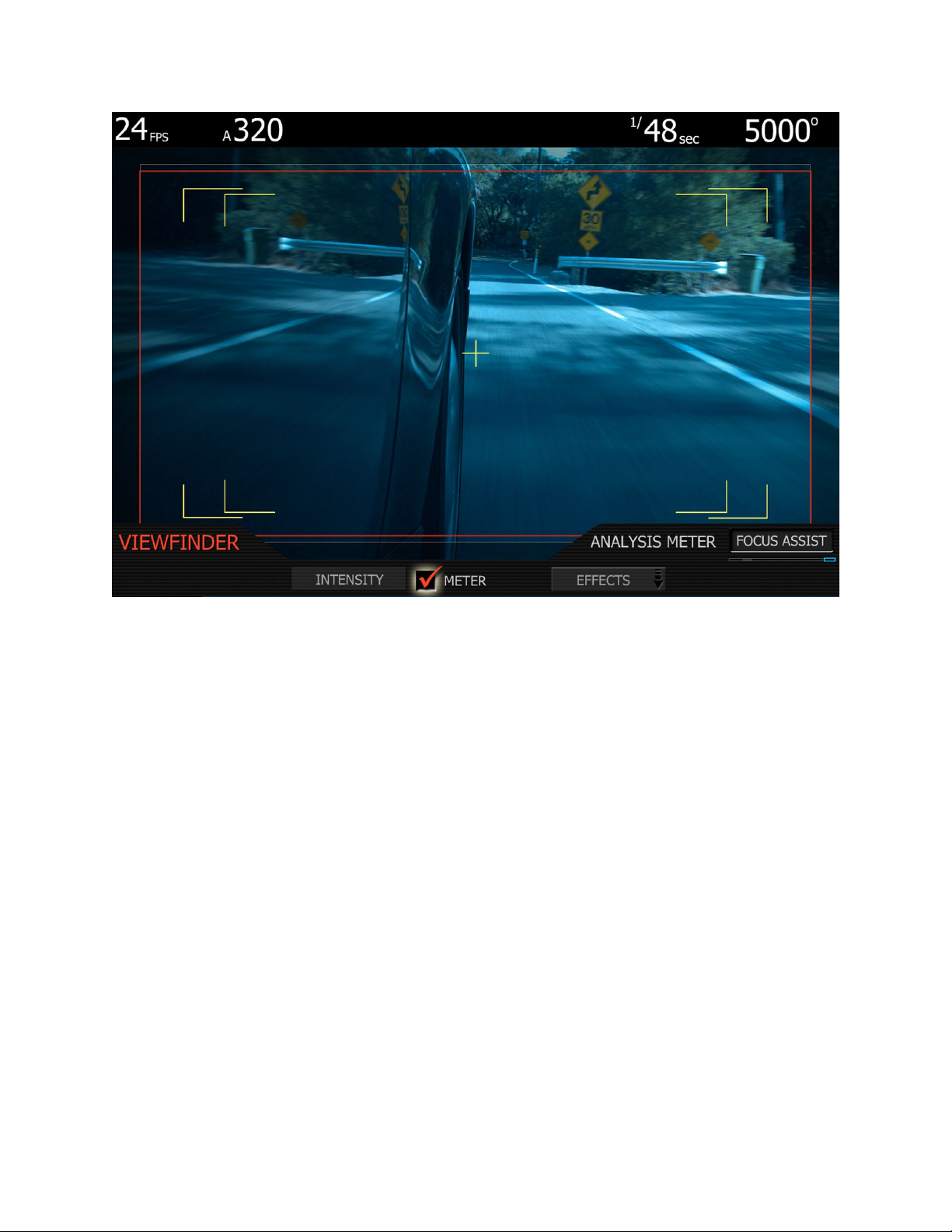
An example of false color metering (from the RED-LCD) is shown below –
And the corresponding white balanced but otherwise unprocessed, source footage – this was
captured at late morning at exposure index A320, 24fps, 1/48th sec shutter and no filtering.
Note the transition of false color in the clouds, indicating clip point was almost reached, the
light grey chair is exposed at approximately 18% gray, and the foliage falls in the shadows.
Page 34

Copyright RED Digital Cinema Feb 07 2008
34
When Edge Highlight is selected the edges of items in focus is outlined.
Met er: allows the operator to choose an “always on” signal analysis. Selections include
Spot Meter, Luma Histogram and RGB Histogram.
If Spo t Me ter is selected, a red rectangular box will appear centered on the center cursor
of the image. The size of this sample box can be adjusted by rotating the Joystick, and its location can be adjusted by moving the joystick in X and Y directions. Press the joystick to fix
the sample box. The average IRE value of the pixels in the sample box is shown in the lower
section of the full camera display.
If Luma or RGB Histogram are selected, a corresponding histogram illustrates the exposure
distribution. The histograms are complimented by a Clip Meter that looks like a traffic light –
but with red, blue and green lamps. When either of the R, G, B channels has 2% of their pixels at the maximum (clip) value, then a corresponding light will illuminate.
Assis ts : allows the operator to choose a signal analysis waveform. Selections include Waveform Exposure, RGB Parade Histogram and Focus Assist.
If Wa ve for m is selected, a color coded waveform illustrates the exposure values using the
full width of the lower section of the camera display. As exposure reaches maximum, waveform color changes to yellow and then red. At minimum exposure, the waveform color
changes to light blue then dark blue. These colors match those used in the False Color Meter.
If RG B Parade is selected, a corresponding histogram illustrates the exposure distribution in
the R, G and B channels using the full width of the lower section of the camera display.
If Foc us A ssist or Fo cus Over lay are selected, a full screen width red rectangular box will
appear centered on the center cursor of the image. The vertical position of this sample box
can be adjusted by rotating the Joystick, and its height can be adjusted by moving the joystick
left or right. Press the joystick to fix the sample box. The average focus value of the pixels in
the sample box are shown in a full width graph restricted to the lower section of the camera
display (Focus Assist) or overlaid in the lower section of the active video (Focus Overlay)
Zebra s: To adjust Zebras, highlight the ZEBRA label, and then push the joystick.
Page 35

Feb 07 2008 Copyright RED Digital Cinema
35
Zebras: enables and adjusts the upper and lower values for two independent Zebra indicators. One zebra may be used for highlight exposure, and the other for mid tone or shadows.
Zebra 1 default settings are for highlight indication with LOW IRE at 90 and HI IRE at 108.
Zebra 2 default settings are for 18% gray indication with LOW IRE at 44 and HI IRE at 47.
To use Zebra 2 as a shadow exposure indicator, set Zebra 2 LOW IRE to 0 and HI IRE to 5.
This corresponds to Dark and Medium Blue in the False Color Meter
Areas of the image exposed within these ranges will be indicated by crosshatched overlays.
Zebra 1 crosshatch pattern is oriented NW/SE and Zebra 2 is oriented NE/SW. Where the
Zebras overlap, Zebra 1 has display priority.
Dar k Deta il : allows the RED-EVF to view addition information (detail) in dark areas of a
scene, or in dimly illuminated nighttime scenes. Default setting is ON, and 2%
Ope n Gate : lets the camera preview images at 48Hz (50Hz) update rate when operating in
23.98 or 24.00 fps (25 fps) Project Frame Rates. In record, all monitor path images will be
viewed at 48Hz, but recorded at 23.98 or 24.00 fps (viewed at 50Hz, recorded at 25 fps)
Note : Op en Ga te i s not ava ilable i n Vari spee d or Ra mp re cord mod es.
Note : Op en Ga te i s not ava ilable f or 2 9.9 7 or h ig her Project F arme Rate s.
Note : I n Build 14 , w hen de sele ctin g Ope n Gate mode, i t is nor mal t o ob ser ve
2 to 3 se con d di sr upti on i n the RED- EVF disp lay.
Page 36

Copyright RED Digital Cinema Feb 07 2008
36
Audio:
This sub menu allows microphone input levels to be adjusted via a high quality pre-amplifier.
Audio is sampled at 24bits, which provides high audio fidelity and wide dynamic range. Each
microphone input is provided with a pre-amplifier that maybe adjusted for optimal level to
match different microphone sensitivities and sound pressures.
Input Level. Range +20dB to +54db Default value is +32dB
Note : I np ut le vel a djus tmen t do es no t ap ply to line le vel audi o inpu ts.
Headpho ne
The sub menu provides controls for headphone output volume channel mixing .
Master Volume: Adjusts the overall headphone volume.
Range is -18dB to 0dB in 1dB steps. Default is 0dB.
Volume Left, Volume Right: Adjusts volume for the left and right sides independently.
Range is -12dB to + 6dB in 1dB steps. Default is 0dB.
Mix: Selects which audio channels feed the left and right side headphone outputs.
1L + 2R Feeds channel 1 to the left side, channel 2 to the right.
3L + 4R Feeds channel 3 to the left side, channel 4 to the right.
Quad Mix Feeds channels 1&2 to the left, channels 3&4 to the right.
Note : Mi x se lectio n a ls o af fe cts the 5p in mi ni-XL R audio line outp ut.
Page 37

Feb 07 2008 Copyright RED Digital Cinema
37
8. Sy stem Menu Con trol s
This section describes the various controls available to configure the camera. These parameters are accessed from the SYSTEM menu key, located below and left of the RECORD button.
The available sub-menus are SOUND, MEDIA, PROJECT, MONITOR and SETUP
Sou nd Me nu
This menu provides audio channel configuration and management.
The sub-menu available at this time is REC ENABLE
Each of the four 24 bit 48KHz sampled audio channels may be independently enabled. Once
enabled, an input type may be selected – either Line or Microphone.
Med ia M enu
This menu provides access to media formatting and other aspects of media management.
The only sub-menu available at this time is REC ENABLE.
Page 38

Copyright RED Digital Cinema Feb 07 2008
38
Mag azi ne Menu
This menu provides various media management functions including digital media formatting.
Unmo unt: select to un-mount digital media from the RED ONE camera in a failsafe manner.
The camera operating system will ensure that all files are closed, hard disk heads (if present)
are parked, log files written and CF card or RED-DRIVE magazine is properly powered down.
For mat: select to format digital media. The camera will warn that “all data will be erased”,
and formatting require that a sequence of confirm commands are made before proceeding.
Note: Media formatted on-camera will generate create a directory name in the format:
Camera Letter + Reel Number + Year + Month + Day. e.g. A001_070512 etc
Proj ect Men u
The project menu sets the operating parameters the camera will use for a given project.
Selections are SLATE, CONFIGURE, TIMECODE and QT PROXIES
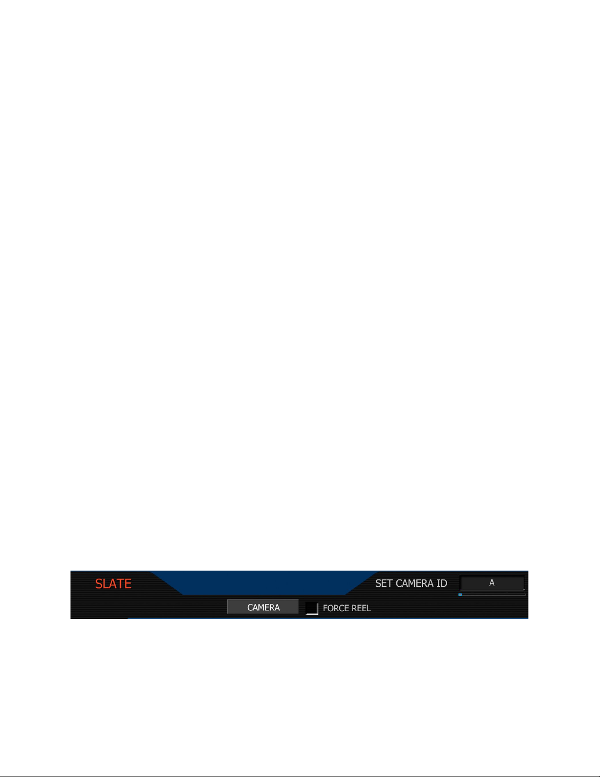
Slat e lets the operator identify the camera and starting reel number for the project, so clips
recorded on the digital media may be easily identified in post-production.
Came ra: is a single letter (A-Z) that provides a unique identifier for the camera in a multicamera production environment. The default camera identifier is A.
When you push record, the camera names the clip being recorded on the digital media. The
format of the clip name is Camera Letter + Reel Number + Clip Number + Year + Month +
Day. For example the clip name might be –
Page 39

Feb 07 2008 Copyright RED Digital Cinema
39
A001_C001_070828.RDC
Where: A = camera A, 001 = reel 001, C001 = clip 001, 07 = 2007 and 0828 = Aug 28.
For ce Ree l: is a number from 1 – 999. Each time a new CF card or RED-DRIVE is mounted
to the RED ONE camera, this number is automatically incremented. Default is 1.
Con fi gure : defines the operation of the camera in a project.
Quali ty. Choose between REDCODE 28 or REDCODE 36. Default is REDCODE 28.
Note: REDCODE 36 limits the available choices of frame rates and resolutions to CF cards.
Fra merate : allows the user to choose any single frame rate.
Reso luti on. Choose 4K, 3K or 2K, or 2:1 variants. Use 2K or 2K 2:1 for S16mm/B4 lenses.
Note: The maximum Projec t Frame Rat e available for each media type per Re solu tion is -
REDCODE 28 CF MEDIA * RED-DRIVE
2K 2:1 59.94 fps 59.94 fps
2K 16:9 59.94 fps 59.94 fps
3K 2:1 50.00 fps 59.94 fps
3K 16:9 29.97 fps 50.00 fps
4K 2:1 25.00 fps 29.97 fps
4K 16:9 25.00 fps 29.97 fps
Page 40

Copyright RED Digital Cinema Feb 07 2008
40
REDCODE 36 CF MEDIA * RED-DRIVE
2K 2:1 59.94 fps 59.94 fps
2K 16:9 59.94 fps 59.94 fps
3K 2:1 29.97 fps 50.00 fps
3K 16:9 29.97 fps 29.97 fps
4K 2:1 25.00 fps 25.00 fps
4K 16:9 n/a 25.00 fps
Note : Va lid com bi nati ons of Qua lity, R esolu ti on and Proje ct Fr ame Rat e are
indic ated by the SE TTIN GS OK chec k mar k. Whe n pr esent, the med ia w ill be
able to execu te the req ue ste d reco rding. If un che cked, the medi a is too slow.
Note that a project can only support one Project Frame Rate. Changing the Project Frame
rate will force a new project and reset the reel number counter. This occurs because the Project Frame Rate defines the fundamental time base used for timecode, clip playback and editing, as well as being the primary frame rate for acquisition.
However variable speed recordings can be made above and below this base frame rate. On
playback, these variable speed recordings will be displayed at the Project Frame Rate.
Time code: select to change displayed timecode track, force Jam sync or reset camera clock.
Jam Syn c: instructs the camera to replace its internal Time of Day value with external timecode read from the 5pin LEMO connector. This value is updated at the first frame of each recording, provided a valid external timecode source is present. If the external source is not
present, the camera auto-increments the timecode until the external source is re-connected.
Disp lay: lets the operator select whether Edge Code or Time Code is displayed in the status
displays. This selection also determines which of the two recorded timecode tracks will be
used in the QuickTime reference movies, and will be embedded in the HD-SDI outputs.
Page 41

Feb 07 2008 Copyright RED Digital Cinema
41
If Edge Code is selected, “E” precedes the value shown in the status display. If Time Code is
selected, "T," precedes the value shown in the status display. Default setting is Time Code.
Time zon e: Applies a time offset to the SET CLOCK value established for the camera.
If camera date and Time are set to GMT, and then set TIMEZONE to –8 for West Coast US
(Pacific) time etc. Or set to local time, and then set the TIMEZONE value to 0.
QT Pr oxie s
When checked, the camera will create QuickTime reference movies at the completion of each
clip record. These movies are placed in the same clip folder. While the reference movies are
being created the camera reports “POST” in the status display. You will not be able to record
until the QuickTime proxies have been created.
Monitor
The monitor menu provides controls for the framing guides and test patterns.
Selections are FRAME GUIDE, ACTIVE, TEST SIGNAL, HD-SDI and EVF REFRESH
Frame Guide: This sub-menu provides a selection of film frame guides and television safe
action and safe title guides. Frame guide elections are recorded in metadata.
Page 42

Copyright RED Digital Cinema Feb 07 2008
42
Fra me G ui de: select one of these aspect ratios 2.40:1, 1.85:1, 16:9 and 4:3 for the frame
guides. The color can be set to White, Black, Blue, Yellow or Red for maximum visibility over
the scene you are shooting.
Prot ect: displays a television safe area with16: 9, 14:9 or 4:3 aspect ratio. The color of the
safe area indicator can be set to White, Black, Blue, Yellow or Red for maximum visibility
over the scene you are shooting.
Cursors: enables combination displays of Safe Action, Safe Title and Image Center cursors.
Page 43

Feb 07 2008 Copyright RED Digital Cinema
43
Active
This sub-menu selects the primary monitoring output of the camera.
Output choices include RED-EVF, RED-LCD, PREVIEW and HDMI. The PREVIEW mode places
720p video on both the Preview HD-SDI and HDMI outputs. To use a DVI computer monitor
as an external viewfinder, select HDMI. This puts 1280 x 848 progressive scan video equal
to the RED-EVF on the HDMI output. Then use a HDMI to DVI cable to connect the monitor.
The EVF+PVW mode permits the RED-EVF and PREVIEW modes to operate simultaneously.
Test Signal
Permits the video monitor outputs to be replaced with a video test pattern
To enable/disable a test signal check the box. Available test signals include: Color Bars, Luminance Ramp, Chrominance Ramp, Chip Chart, Black and Gray Field.
Note : T he tes t si gnals ca nnot be r ec orde d to t he d igital me di a, they are p rovided t o help alig n the z ebra s a nd exte rna l video recor de rs or monitors co nnecte d to the c amer a vi a the HD- SDI or HD MI por ts.
HD- SDI
Sets the1280 x 720p HD-SDI and HDMI monitor signal update rate to 50.00 or 59.94 Hz.
The default is 59.94 (720p 59.94) In Europe you may wish to select 50.00 (720p/50.00)
Page 44

Copyright RED Digital Cinema Feb 07 2008
44
EVF R efre sh
When capturing images at normal frame rate and 23.98, 24.00 or 25.00 fps Project Frame
Rates, refresh permits the operator to select the display refresh rate used by the RED-EVF.
The default mode is SYNCED. This avoids use of 2:3 pull down, and instead doubles the capture frame rate to display images at 48Hz (50Hz for 25.00 fps). The display may exhibit increased luminance flicker do to the lower frame update rate, but will not have a 2:3 stutter.
The alternative FIXED mode uses 2:3 pull down or other appropriate pull down sequences
required to displays images at a fixed frequency of 59.94 Hz (or 50Hz) at all capture frame
rates. This mode minimizes display flicker but may exhibit 2:3 motion stutter on 24fps images.
Note : T he cam era will o perate in F IX ED mo de w hen the P roje ct Fra me Ra te i s
other t han 23.98 , 24 .0 0 or 25 .0 0, a nd also whe n i n VariSpee d or Ra mp.
Setup
This menu permits a variety of system maintenance tasks to be accomplished.
Selections are PREFERENCES, MAINTENANCE and SET CLOCK
Preferences: permits the user to define system preferences.
Selections are KEY MAP , GPIO and LOOK
Note: In Build 14 the LOOK menu i s not fully operational
Page 45

Feb 07 2008 Copyright RED Digital Cinema
45
KEY MAP: this menu permits selected menus or functions to be mapped to camera keys.
At this time the Key-Map function can be used to enable or disable the Side Record, User-1
(Auto WB) and User-1 (Magnify) function keys. The default setting for each is Enabled.
GPI O: this menu permits selected menus or functions to be mapped to camera keys.
This menu permits the function of GPI A and B defined as either -
Record: triggers a normal video and audio record start / stop.
Burst: triggers a one shot or burst mode timelapse recording.
Ramp: triggers a variable frame rate ramp speed change.
For GPI A the factory default is Recor d and for GPI B factory default is B ur st.
Pola rity selects the Polarity sub-menu.
This menu permits the signal polarity of GPI A and B and GPO A and B to be defined as either – Active LO or Active HI. Selection is independent for each GPI input and GPO output.
For GPI signals Active LO is the default, which means the GPI command will be activated on
a high to low edge of an external control pulse. Set to Active HI to use a low to high edge.
For GPO signals Active HI is the default, which means the GPO tally output will be high when
in normal, burst or ramp record modes, and low when not. Set to Active LO to reverse this.
Page 46

Copyright RED Digital Cinema Feb 07 2008
46
Maintenance
This sub-menu defines how the cooling fan behaves, and enables software updates.
Fan Sub Menu: specifies how the cooling fan operates.
The camera's fan speed can be changed depending on the ambient air temperature and recording application. The default setting is VARIABLE.
Vari able : This setting is most useful when the ambient temperatures is below 50°F/10°C. In
variable mode, the fan runs at a continuously variable speed in both preview and record. At
low ambient temperatures the fan will run at minimum speed. At higher ambient temperature,
the fan will run at an increased speed to maintain the camera body within its operating temperature limits.
Hot: This setting is most useful when the ambient temperature is between 86°F/32°C and
104°F/40C. In hot mode, the fan runs at its maximum speed. Other camera cooling precautions may be necessary, such as shading the camera from sunlight and use of a cold gel pack.
Sta nd ard: This setting is most useful when the ambient temperature is below 86F/ 32C. In
standard mode, the fan will run at half its maximum speed when in record.
Quiet: This setting is most useful when the ambient temperature is below 72°F/25°C. In
quiet mode the fan runs at one quarter its maximum speed when in record.
Sile nt: This setting is most useful when the ambient temperature is below 60°F/15°C. In silent mode the fan runs at its minimum speed when in record.
Auto : This setting combines VARIABLE speed fan operation while not recording, with SILENT
mode when in record. This mode is recommended for extended duration dialog recordings.
Black S ha ding: allows the camera to self-calibrate the sensor for optimum black levels.
Page 47

Feb 07 2008 Copyright RED Digital Cinema
47
Note : bef ore starti ng a Bla ck S ha ding cal ibra ti on, ensu re that you p lace a le ns
cap that b locks al l light on y our le ns , clo se t he len s iris, a nd i nser t a fo rmatt ed
CF ca rd into t he c amer a (o r atta ched a form atted RED- DRI VE ) I t is ver y impo rtant that no l ight r eac he s the sens or. If Bl ack S ha ding cal ibra tion i s pe rfor med
wit ho ut cappi ng the lens , the blac k leve l ca li brat ion wi ll b e inc or rect . To r ectify, r ep eat the pro ce dure w ith a lens cap ins ta lled.
Press the BLACK SHADING button, the camera monitoring outputs will report -
Star t R estore
Press the START button, the camera monitoring outputs will report -
You are about t o mod ify the ca mer a’s f acto ry caiib rati on. You
sho ul d take this step only w hen advis ed t o do s o by a factor y re pr ese nt ative. B efor e co ntin ui ng, mak e sure t he le ns cap is se cur ely in place. The
sensor mus t re mai n unex pose d to l ight for the dur at ion of t hi s pro ce ss
Press the O.K button, the camera monitoring outputs will report -
Star ting Bla ck S ha ding Ca li br atio n
The camera will then enter the Record mode, and any camera monitoring outputs will report -
Cal ibra tion: Analyzi ng Se ns or (9 9)
The camera records 100 frames of sensor data that is used to analyze the black level of each
pixel. This will take about 2 minutes. After that time the camera will report -
Black S ha ding: Prep ari ng / M ergi ng / Ca lculating / Wr iting
Finally the camera will report -
Black S ha ding: Inst alli ng
Installation of the new data takes about 3 minutes. The camera will then report -
Black S ha ding Cal ib rati on w as su cces sf ul .
Plea se r eboot the camer a fo r th e ne w se tting s t o ta ke e ffect.
Power cycle the camera. This completes the Black Shading calibration procedure.
Page 48

Copyright RED Digital Cinema Feb 07 2008
48
Rest ore: permits camera configuration and setup data to be reset to factory default values.
System – Allows all camera configuration parameters to be reset to factory preset.
Look – Allows all image processing parameters to be reset to factory preset.
User - Allows all user preference parameters to be reset to factory preset.
Restore – Press the RESTORE key to confirm the above selections.
Upd ate SW: initiates a camera software update.
Details of the upgrade procedure are provided in the following section of this Guide
Set Clock : allows the camera’s time and day metadata to be reset.
Set Date and Time to equal GMT, and then set TIMEZONE in the TIMECODE menu to –8 for
West Coast US (Pacific) time. Or set to local time, and then set the TIMEZONE value to 0.
Year – allows the operator to enter a new value for the year Range 2007 - 2020
Month – allows the operator to enter a new value the month Range 1 - 12
Day – allows the operator to enter a new value for the day. Range 0- 31
Page 49

Feb 07 2008 Copyright RED Digital Cinema
49
Hours – allows the operator to enter new value for hours (24 hour format) Range 0 - 23
Minutes – allows the operator to enter new value for seconds. Range 0 - 59
Seconds – allows the operator to enter new value for seconds. Range 0- 59
Set Clock – loads the selected Date and Time parameters into the camera’s system memory.
Note : A ft er pre ssi ng t hi s key the c amer a w ill re -boot. The ne w parame te rs w ill
take eff ect, a nd b e visi ble as TI ME CO DE, on co mple tio n of t he r e-boo t cy cle.
Page 50

Copyright RED Digital Cinema Feb 07 2008
50
9. Up gr adi ng Ca me ra Fir mware
RED-ONE camera functionality may be upgraded by installing the latest firmware.
Log onto www.red.com/support for a complete listing of firmware revisions available for the
camera, complementary QuickTime codec, postproduction software, and Operation Guide.
Upgr ade Pro cedure
Firmware and software identified by a build and version number. A higher number reflects a
later release. The current release is identified on the home page of www.red.com web site.
To download, click on the desired release’s link at ww.red.com/support. Before the download starts you will be prompted to enter your account and password or the camera’s P.I.N.
Once the firmware is downloaded, you will see a new folder on your desktop. Open that
folder and verify you see a read me file (containing installation instructions), and a folder
called Upgrade. Now take either an SD Card or a CF card that has been formatted by the
camera, and use your computer to copy the folder called Upgrade onto that SD or CF card.
Finally, unmount the SD or CF card from the computer (i.e. drag to the trash can) and insert
the SD or CF card into its corresponding slot in the camera. To initiate the upgrade, turn off
the camera, wait approximately ten seconds, and then turn on the camera again.
If there is valid upgrade firmware on the SD or CF card, all monitor outputs will report back -
Page 51

Feb 07 2008 Copyright RED Digital Cinema
51
Press the joystick to confirm the upgrade, all monitor outputs will report back -
The blue highlight bar will animate to indicate an upgrade is in progress. After about 5 minutes, the upgrade will have completed. All monitor outputs will report back -
Power cycle the camera to return to normal operation. At the end of the camera power up
process, the camera will display the camera P.I.N plus firmware Build and Version numbers.
Note : A ft er upg radi ng ca mera fir mwar e, perfor m a B la ck Shading Calibrat ion.
Page 52

Copyright RED Digital Cinema Feb 07 2008
52
10. Man aging Digi tal Media
The RED-ONE camera currently supports two types of media - compact flash and hard disk.
Compact Flash (CF) media requires an optional RED-FLASH (CF) module mounted to the left
side of the camera body. Hard disk media is housed in a RED-DRIVE magazine mounted to
the rear of the camera body and connected via a custom16 pin interface cable.
Com pact F lash (CF) - will be available in a variety of capacities, but at this time is fixed at
8GB. Depending on resolution and frame rate, each 8GB Compact Flash card will provide
over 4 minutes of 4K 24fps RAW recording, or over 12 minutes of 2K 24fps RAW.
RED- DRI VE Me di a - will be available in a variety of capacities, but at this time is fixed at
320GB. Depending on resolution and frame rate, each 320GB RED-DRIVE will provide approximately 180 minutes of 4K 2:1 24fp RAW recording, or 720 minutes of 2K 24fps RAW.
During a recording the rear status screen, RED-EVF and RED-LCD monitors will display the %
remaining media capacity. At 5% remaining capacity the media status box in the EVF or LCD
will turn yellow, at 3% it will turn red. At 2% remaining the camera will cease recording. This
reserves a small amount of capacity for ancillary data files to be written to the digital media.
Note: Media formatted on-camera will generate create a directory name in the format:
Camera Letter + Reel Number + Year + Month + Day. e.g. A001_070512 etc
Clips recorded to the media follow a similar naming convention e.g. A001_C001_07512 etc
Med ia For matt ing
Media must be formatted prior to using it for recording. At this time formatting must be done
on the camera. Media may be pre-formatted (erased) on a Macintosh OS X or Windows XP
personal computer, allowing the camera to add the necessary project format data.
For matting o n-ca mer a
i) Formatting a new Compact Flash card or RED-DRIVE magazine.
Insert the CF card with the manufacturer’s label facing outward (away from camera body).
Press the CF firmly into the CF slot, but without excessive pressure. Or attach the RED=DRIVE
magazine to the e-SATA port via the 16 pin e-SATA cable provided. The camera will recognize unformatted media and prompt with a message such as this -
Page 53

Feb 07 2008 Copyright RED Digital Cinema
53
Press the Joystick to confirm, or select Cancel to return to the main camera status display.
If the format operation is confirmed, the camera responds with the following message -
Formatting INTERNAL /EXTERNAL digital magazine
Once completed the following screen will appear.
Press the Joystick one last time to acknowledge the format process is complete and the camera will then clear the system menus from the monitor screens. Formatting a 8GB CF card
takes about 10 seconds; formatting a 320GB RED-DRIVE magazine takes about 50 seconds.
Note: Media formatted on-camera will generate create a directory name in the format:
Camera Letter + Reel Number + Year + Month + Day. e.g. A001_070512 etc
Refo rma tt ing pr eviously us ed me di a
Re-formatting a previously used CF card or RED-DRIVE magazine follows a similar procedure,
except that the camera provides the following modified warning.
Page 54

Copyright RED Digital Cinema Feb 07 2008
54
Press the Joystick to confirm, or select Cancel to return to the main camera status display.
Eras ing med ia o n a M aci ntosh pe rso nal computer
On a Macintosh computer, connect the CF card via a CF card reader, or the RED-DRIVE via a
FireWire 400 cable. Open the Disk Utility application, and then select the CF card or REDDRIVE.
Select the Erase tab and choose MS-DOS File System as the Volume Format. Add a Name if
you wish, but this is optional. Before proceeding, double check that this is the CF card or REDDRIVE that you wish to erase, and then click on the Erase key. When the pop up window appears click on the Erase button
When the media is erased, drag its icon to the trashcan and physically disconnect it. When
mounting erased media on the camera it will be treated as unformatted media and will follow
the same formatting rules as described above.
Page 55

Feb 07 2008 Copyright RED Digital Cinema
55
Remo vi ng Me dia.
It is recommended that media is un-mounted prior to physical removal from the camera. This
ensures that power is removed from the digital media and any open data files are closed.
Physical removal of the CF card or disconnecting the RED-DRIVE without first un-mounting it
will not damage the media, but can increases the risk of file corruption, especially if data is
being recorded. In addition, auxiliary metadata files cannot be written to the digital media.
To UNMOUNT the digital media follow this sequence.
- Press and hold the UNDO key and then press the EXIT key.
When the status indicator displays “Safe to Remove” and “ X ” as media status, it is safe to
remove the CF card and/or disconnect the RED-DRIVE magazine.
The modest extra step of un-mounting the digital media helps recorded clips mount instantly
in postproduction. Failing to unmount before removing the digital media will not damage the
recorded clips themselves, but it can increase the risk of corrupting the clip index file.
Cop ying Med ia.
When copying media it is recommended that the entire contents of the digital magazine are
copied to the storage media. This ensures that all appropriate media and data are copied.
Note : You do n’t need to cop y the PI N.lo g, d ig ital.mag azine. profi le and dig ital. magdyna mi c.pr ofile . fi le s, b ut will als o do no har m if you do.
Page 56

Copyright RED Digital Cinema Feb 07 2008
56
Appendix A: Post Production.
RED workflow is quite easy to understand, especially if you have experience with photographic
RAW image processing, or shoot film followed by telecine transfer to a non-linear video editor.
RAW data has a wide dynamic range and color space, so you can freely change the white
point (white balance) of the footage, adjust exposure and alter highlight and shadow tonality
when in post-production. This flexibility allows the camera operator to focus on composition.
The camera records unprocessed sensor data using REDCODE RAW compression to a CF card,
or RED-DRIVE digital magazine. Data is then transferred from the digital media via FireWire or
USB-2, to a Macintosh OSX workstation running RED ALERT! or REDCINE software, or a Windows XP workstation running REDCIINE software. If you are using CF media, copy the clips
onto the workstation’s hard drive. If you are recording to a RED-DRIVE, it can be directly
mounted as an external drive using FireWire if desired which eliminates the media copy step.
In film processing terms, RED ALERT! and REDCINE act as an integrated laboratory, telecine,
and one light color corrector. They convert recorded REDCODE RAW data to RGB video, and
provide basic one light image processing and color correction. Using REDCINE, footage can
also be cropped, resized, or repositioned. These functions lessen the amount of time required
for color correction or re-framing of shots after the final cut has been completed.
RED ALERT! can generate QuickTime reference movies suitable for use in dailies applications,
and export a sequence of 2K or 4K resolution RGB image files as TIFF or DPX files for DI use.
REDCINE can also encode 4K or 2K RAW footage into a variety of uncompressed RGB and
compressed 4:2:2 video formats. Provided the appropriate QuickTime codec’s are available on
the host computer workstation, compressed video choices include ProRes, DNxHD, DV100 and
M-JPEG QuickTime movies at 1080p or 720p resolution. For film out, multi-media or special
effects applications, REDCINE may export a sequence of 2K or 4K image files in TIFF, Open
EXR, DPX, JPEG, or Photoshop PSD file formats.
Creating 4:2:2 at 1080p or 720p resolution QuickTime movies provides compatibility with the
majority of non-linear editing systems. Depending on the QuickTime movie resolution, material
may be taken directly to a broadcast delivery videotape format, or after the editorial decisions
have been made, video can be conformed at full image resolution by replacing the lower resolution edit proxy (e.g. 720p at 8 bit quality) with a high resolution 4K, 2K or 1080p image file.
Color grading may be performed during editing or after the final conform. The graded show is
then output to delivery media: film, a DCDM (digital cinema distribution master), or HD master.
Page 57

Feb 07 2008 Copyright RED Digital Cinema
57
Software Tools
RED Digital Cinema provides a variety of software tools to aid postproduction. For proper color
rendition using a Macintosh OSX computer, your monitor should be set to Adobe 1998, or to
SMPTE-C display profile. If you use the HD Cinema display profile, adjust the gamma to 2.2.
REDCODE RAW QuickTime Co mp onent
The REDCODE RAW QuickTime component permits REDCODE RAW footage to be displayed
on Macintosh OSX or Windows XP personal computers with QuickTime Player V7.0 or higher.
QuickTime player
The render performance of computers will vary based on CPU speed, number of cores and disk
speed. Therefore the RED ONE camera RED ALERT! and REDCINE offer QuickTime reference
movies at _H high 2048 x 1152, _M medium 1024 x 576, and _P proxy 512 x 288 resolutions for 4K and 4K 2:1 RAW recordings, and _H high 1024 x 576, _M medium 512 x 288
and _P proxy 256 x 144 resolutions for 2K and 2K 2:1RAW recordings.
Choose the resolution that is most appropriate to your requirement for resolution or playback
frame rate on your specific computer. If the footage is to be viewed at distant location – e.g.
dailies - export the footage as a standalone movie using MPEG-4 or other low bit rate codec.
Note: The QuickTime reference movies work by partially decoding the wavelet data, which
means that the original 4K or 2K REDCODE RAW recording must be available on a drive accessible to your computer. For remote use, conversion to a standalone movie avoids this issue.
Page 58

Copyright RED Digital Cinema Feb 07 2008
58
RED A LE RT!
The RED ALERT application performs white balance and one light color correction and exports
4K and 2K resolution 10 bit DPX and 16 bit TIFF files. RED ALERT also creates color corrected
QuickTime reference movies for playback in other applications, such as QuickTime Player, that
use the REDCODE RAW QuickTime component described above.
The upper panel in the display provides information about the video levels in the selected clip.
Exposure and White Balance may be altered, R G and B digital values may be sampled from
the image, and a Zebra exposure indicator can be selected – the default value is set at 95%
A composite RGB histogram may be selected which appears below the main display area. This
provides an interactive view of the exposure distribution for each of the R G B channels.
A one light color correction panel permits adjustment of Color Temperature, Saturation, Contrast, Brightness, R Gain, G Gain and B Gain. These parameters match those available in the
RED-ONE camera. The range and resolution of these parameters may be greater than those
available in the camera UI. This reflects the desirability for greater range and precision for the
controls in post-production than are required for monitoring in image capture.
Page 59

Feb 07 2008 Copyright RED Digital Cinema
59
RED ALERT! reads the camera metadata recorded for each parameter. Individual values can be
changed by dragging the slider, or by entering a new numeric value in the box. Clicking R will
reset the value back to its default setting. Clicking M will restore the recorded metadata value.
R ALL or M ALL will affect all parameters, GRADE will revert all values back to those last used
in your color grade.
Presets are available to establish a consistent “look” across multiple clips, or alternative color
treatments may be made to the same clip. In future, looks may be shared with the camera.
The image may be displayed using REC 709, linear or a variety of log color space. If Matrix is
unchecked and display is set to Linear, the data that is drawn on screen represents the native
linear response of Mysterium™ without any color processing or gamma correction applied. For
most television applications, select REC 709. For special effects, use Linear. For D.I use a Log.
The timeline controls permit the user to play selected clips and mark an IN and an OUT points,
between which the TIFF or DPX file sequence will be extracted. When creating any QuickTime
reference movies the entire clip will be referenced, as trimming will be performed downstream.
If a single frame is to be exported, press Save 4K or 2K DPX, or 4K or 2K TIFF. If a sequence
of frames is desired, press Save Sequence 4K or 2K DPX, or 4K or 2K TIFF.
Page 60

Copyright RED Digital Cinema Feb 07 2008
60
Appen dix B: Powe r and Timec ode I/O.
D.C Power Inp ut
The power input connector accepts a DC voltage between +11.5 and +17V DC. When used
with a RED-BRICK 140 battery, the camera also receives battery status information. The power
input is protected against reverse-polarity connection, ESD, under voltage, and over current.
Mating connector LEMO FGG.2B.306.CLAD62Z (straight)
1
2
3
4
5
6
View int o ca mera P ower I npu t conn ec tor
Pin
Signal
Descri p tion
1
2
+VBATT
Power input, +11.5 to +17VDC
3
4
-VBATT
Power return
5
SCL_BATT
Battery pack I2C bus clock
6
SDA_BATT
Battery pack I2C bus bi-directional data
Note : It i s ver y impo rta nt that both of the +V BATT and –VB ATT p ins are wi re d
up. DO NOT fabricat e any power c abl es wit h just one e ach of t he +V BAT T and
–VB ATT pi ns w ired up, as this can damag e th e ca mera p ower suppl y asse mbl y.
Auxil ia ry P ower Outp uts
The camera provides two auxiliary power output connectors on its back panel. Each supplies
un-regulated +11.5 – +17V battery pass-through power. Maximum sustained current draw is 1
Amp per output. Outputs are over-current protected, and switched by camera firmware.
Mating connector LEMO FGG.0B.304.CLAD42Z (straight)
1
4
3
2
View int o ca mera A uxiliar y P ower Out put c on nect or
Page 61

Feb 07 2008 Copyright RED Digital Cinema
61
Pin
Signal
Descri p tion
1
-VOUT
Auxiliary power return (Ground)
2
GPI
Trigger
3
GPO
Tally
4
+VOUT
Auxiliary power output,
Note: Commencing with Build 10 firmware, Pins 2 and 3 can be used to provide an external
Trigger and Tally signal. The function of each GPIO pin can be configured by the operator,
however the default setting for the upper connector is Pin 2 = Record Start/Stop and Pin 3 =
Record Tally. For the lower connector, the default setting is Pin 2 = Record Next Frame and
Pin 3 = Frame Record Completed. Use this for animation or simple motion control interface.
Time code Inpu t
This connector supports SMPTE Timecode input and output. Pins 2 and 3 may be used together
to receive a balance SMPTE 12M serial time code input, or pin 2 may be used by itself (leave
pin 3 open) to receive a single-ended SMPTE 12M serial time code input.
Mating connector: LEMO FGG.0B.305.CLAD42Z (straight)
1
2
3
4
5
View int o ca mera T i mecod e c on ne ct or
Pin:
Signal
Description
Direction
1
Ground
Camera ground
-
2
TIMECODE_IN_P
Serial timecode input, positive
in
3
TIMECODE_IN_N
Serial timecode input, negative
in
4
-
-
-
5
-
-
-
Note: Pin 5 is reserved for future use for single-ended SMPTE 12M serial time code signal out.
Page 62

Copyright RED Digital Cinema Feb 07 2008
62
Len s / RS23 2
This connector provides 500mA regulated +12V power to motorized 2/3” B4 mount lenses.
The two inputs labeled SW1 and SW2 are GPI switches that activate Record Start / Stop and
last recorded Clip Playback respectively. They may be triggered by a standard B4 lens, or by a
lens motor controller such as Preston MDR-2 (using an appropriate adaptor cable)
Note: DO NOT attempt to power a cinema lens motor from this connector. Depending on your
current requirement, power from an Auxiliary Power output or D-Tap connector on the V-Plate.
Mating connector: LEMO FHG.1B.310.CLAD62Z (right angle)
5
10
8
2
9
7
6
4
3
1
View int o ca mera L en s / R S2 3 2 con ne cto r
Pin:
Signal
Descri p tion
Directi on
1
GND
Ground
--
2
-
-
-
3
+12V
Regulated 12V output, 500mA max.
Out
4
-
-
-
5
SW2
“Record Clip” switch closure
In
6
-
-
-
7
SW1
“Playback Clip” switch closure
In
8
-
-
-
9
-
-
-
10
-
-
-
Note: pins 2 and 8 are reserved for future use as RS232 transmit and receive signals.
Page 63

Feb 07 2008 Copyright RED Digital Cinema
63
Line/ Micr ophone Audio Inp uts
The camera includes four microphone/line inputs. Each is a three-pin mini-XLR connector.
12
3
View Into Mic/Line Audio Input (3-pin Mini-XLR)
Pin:
Signal
Description
Direction
1
GND
Camera ground
--
2
IN+
Mic/Line input (+48V phantom power)
In (out)
3
IN-
Mic/Line input (+48V phantom power)
In (out)
Microphone/Line Input Signals
Line Audi o Output
The camera includes a 5-pin mini-XLR audio line output connector.
Pin:
Signal
Description
Direction
1
LEFT+
Line output, left channel
Out
2
3
LEFT-
Line output, left channel
Out
4
RIGHT+
Line output, right channel
Out
5
RIGHT-
Line output, right channel
Out
Microphone/Line Input Connectors
Headpho ne Audio Out put
The camera includes a 3.5mm phone jack for headphone audio output.
Pin:
Signal
Description
Direction
tip
LEFT
Left channel audio
Out
ring
RIGHT
Right channel audio
)ut
sleeve
GND
Ground
--
Stereo Headphone Output Connector
Page 64

Copyright RED Digital Cinema Feb 07 2008
64
USB Hos t
A standard USB 2.0 Type A receptacle provides a means to connect USB devices to the cam-
era. Refer to the USB specification for mating connectors and pin assignments.
USB Device
A standard USB 2.0 Type B receptacle provides a means to connect the camera to a USB host
– e.g. a P.C. Refer to the USB specification for mating connectors and pin assignments.
Ge nlo ck I nput
The camera includes a DIN 1.0/2.3 coaxial connector on its right side panel for Tri-Level Sync.
Pin:
Signal
Description
Direction
Center
GENLOCK
SMPTE274M-2005Tri-levelSync
in
Shield/Screen
Ground
Ground
--
Genlock Input Signal
Pre vi ew HD-S DI
The camera includes a DIN 1.0/2.3 coaxial connector on its right side panel for the HD Pre-
view signal, which is 1280 x 720 progressive 10 bit 4:2:2 HD-SDI output at 59.94 or 50.00Hz.
Pin:
Signal
Description
Direction
Center
HD-SDI
SMPTE-292M HD-SDI
out
Shield/Screen
Ground
--
--
Monitor HD-SDI Output
Single/Dual -li nk HD- SDI
The camera includes two DIN 1.0/2.3 coaxial connectors on its right side panel. The dual link
HD-SDI output is fixed in Build 12 firmware as additional copies of the HD Preview signal.
Pin:
Signal
Description
Direction
Center
HD-SDI
SMPTE-292M HD-SDI
out
Shield/Screen
Ground
--
--
Capture HD-SDI Output (each connector)
HDM I
The camera includes a standard HDMI Type A connector on its right side panel. This output
may provide a HDTV compatible 1280 x 720p or SXGA compatible 1280 x 848p signal.
 Loading...