

RED EPIC
OPERATION GUIDE
EPIC-M & EPIC-X / BUILD V4.0
RED.COM

RED EPIC OPERATION GUIDE
TABLE OF CONTENTS
DISCLAIMER 5
COPYRIGHT NOTICE 5
TRADEMARK DISCLAIMER 5
COMPLIANCE 6
INDUSTRIAL CANADA
EMISSION COMPLIANCE
STATEMENTS 6
FEDERAL COMMUNICATIONS
COMMISSION (FCC)
STATEMENT 6
AUSTRALIA AND NEW
ZEALAND STATEMENT 7
JAPAN STATEMENTS 7
EUROPEAN
UNION COMPLIANCE
STATEMENTS 7
BEFORE YOU START 10
IMPORTANT SAFETY
INSTRUCTIONS 10
READ BEFORE USING YOUR
CAMERA 10
THEORY OF OPERATION 13
MYSTERIUM X® SENSOR 13
IMAGE PROCESSING 13
HDRX™ 14
MAGIC MOTION™ 15
AUDIO RECORDING 15
MICROPHONE LEVEL ANALOG
INPUTS 15
LINE LEVEL ANALOG INPUTS
16
VIDEO MONITORING OUTPUTS
16
BOMB EVF 17
RED TOUCH LCD 17
HD-SDI 17
HDMI 17
REDMOTE® 18
DIGITAL MAGAZINE (MEDIA) 18
METADATA 19
CLIP NAMING CONVENTIONS 20
SMPTE TIMECODE 20
POWER CONSUMPTION 21
CAMERA OPERATIONAL
CONTROLS 21
BRAIN 21
SIDE SSD MODULE 22
SIDE HANDLE 23
TOP 23
FRONT 24
REAR 25
INSTALLATION / REMOVAL 26
DSMC MODULES 28
PRO I/O MODULE 28
REAR SSD MODULE 29
QUAD BATTERY MODULE 29
DUAL BATTERY MODULE 30
MODULE INSTALLATION / REMOVAL
30
REDMOTE 34
NAVIGATION GROUP 35
DISPLAYS 35
BOMB EVF AND BOMB EVF (OLED)
35
TOUCHSCREEN LCD 37
BASIC OPERATION 38
POWER SOURCES 38
SIDE HANDLE 38
QUAD BATTERY MODULE 39
REDVOLT AND REDVOLT XL 39
BACKPACK QUICKPLATE 40
AC POWER ADAPTOR - (DSMC) 41
EXTERNAL DC POWER 43
POWER UP 43
POWER DOWN 44
GRAPHICAL USER INTERFACE
AND NAVIGATION 45
RED LCD/TOUCHSCREEN LCD,
BOMB EVF, EXTERNAL MONITORS45
SIDE HANDLE 52
REDMOTE 52
NAVIGATING MENUS 53
USING TOUCHSCREEN LCD 53
TOUCHSCREEN SHORTCUTS 55
ACCESSING SOFT KEYS 56
POWER DOWN 57
LOCK / UNLOCK TOUCHSCREEN
OPRERATION 58
FIRST TIME USE –
SETTING UP YOUR RED
EPIC 59
ATTACH POWER SOURCE 59
BATTERY 59
QUAD BATTERY MODULE 60
RED BRICK 60
DC POWER 60
POWER UP 61
PREPARING TO RECORD 61
CONNECT AND FORMAT MEDIA 61
PERFORM A BLACK SHADING
CALIBRATION 62
ADJUST PROJECT SETTINGS 62
RECORDING 64
RECORD INDICATOR 65
PLAYBACK 66
MENU CONTROLS 67
ADJUSTMENTS 67
BASIC SETTING ADJUSTMENTS 67
ADVANCED SETTING MENUS 68
MAIN MENU 69
FPS 69
VARISPEED 69
BASIC SETTINGS 70
ADVANCED SETTINGS 70
ISO (SENSITIVITY) 71
F STOP 71
EXPOSURE 73
BASIC SETTINGS 73
ADVANCED SETTINGS 74
WHITE BALANCE 76
BASIC SETTINGS 76
ADVANCED SETTINGS 77
RESOLUTION 78
REDCODE 79
REDCODE OPTIONS FOR VARIOUS
FRAME RATES 79
SECONDARY MENUS 80
HDR MENU 80
HDR ON / OFF 80
STOPS 81
FOCUS MENU 81
MODE 82
ZONES 84
ENHANCED A/F 87
LENS INFORMATION DISPLAY
91
RED DSMC TI PL MOUNT + LENS 91
DSMC CANON MOUNT + LENS 91
EXPOSURE MENU 92
COPYRIGHT © 2013 RED.COM, INC
955-0002_v4.0, Rev-A | 2

RED EPIC OPERATION GUIDE
PRESETS MENU 92
CAMERA PRESETS 92
LOOKS PRESETS 96
AUTO PRESETS 97
MEDIA MENU 97
SELECT MEDIA 98
FORMAT MEDIA 98
EJECT MEDIA 99
UTILITIES 99
SETTINGS MENU 101
DISPLAY 101
LOOK 119
PROJECT 122
SYSTEM STATUS 125
AUDIO 125
RECORDING 128
SETUP 135
MAINTENANCE 144
PLAYBACK 154
POWER 160
POWER STATUS 160
SHUTDOWN 161
POWER OUT 162
POWER SAVE 162
APPENDIX A:
UPGRADING CAMERA
FIRMWARE 164
VERIFY CURRENT CAMERA
FIRMWARE 164
UPGRADE PROCEDURE 164
RESTORE DEFAULT FACTORY
SETTINGS 164
APPENDIX B: MANAGING
DIGITAL MEDIA 165
MEDIA 165
FORMATTING MEDIA 165
MEDIA CAPACITY REMAINING
STATUS 167
EJECT MEDIA FROM CAMERA
(UNMOUNT) 167
USING REDMOTE / TOUCHSCREEN
LCD 168
USING SIDE HANDLE 169
USING SIDE SSD 169
COPYING MEDIA 169
ERASING MEDIA 170
MACINTOSH OS X 170
WINDOWS 170
APPENDIX C: INPUT /
OUTPUT CONNECTORS 171
CAMERA BRAIN FRONT 171
MIC-1, MIC-2 (MICROPHONE AUDIO)
172
CAMERA BRAIN REAR 173
HD-SDI 174
HEADPHONE 174
SYNC (VIDEO SYNC) 175
CTRL (RS232 CONTROL) 177
GIG-E (ETHERNET) 178
DC IN (POWER INPUT) 179
HDMI OUT 180
SIDE SSD MODULE 180
REDMOTE 181
APPENDIX D:
SUPPORTED LENSES 182
DSMC CANON MOUNT
ELECTRONICALLY
SUPPORTED LENSES 182
DSMC NIKON MOUNT
ELECTRONICALLY
SUPPORTED LENSES 183
DSMC LEICA-M MOUNT
LENSES 183
APPENDIX E: AUDIO
SUBSYSTEM
INFORMATION 184
AUDIO FORMAT 184
CHANNEL SETUP 184
SOURCE SELECTION 184
CHANNEL MODES 185
BALANCED MICROPHONE 185
UNBALANCED MICROPHONE 185
LINE IN 0 DBU 186
LINE IN 0 VU 186
PHANTOM POWER 186
LIMITER 186
AUDIO RECORDING 186
PEAK METER 187
DATA PATH 188
HD-SDI/HDMI EMBEDDED
AUDIO 188
AUDIO DURING PLAYBACK 190
APPENDIX F: DEFAULT
KEY FUNCTIONS 192
APPENDIX G: REDMOTE
OPERATION 194
CONTROL, CONNECTORS AND
DISPLAY 194
CONTROLS 194
OPERATION 197
DOCKING AND UNDOCKING 197
POWER UP / DOWN 198
RECORDING 199
ACCESSING CAMERA CONTROLS /
SETTINGS 200
ADVANCED OPERATION: REDMOTE
MENUS 201
INTERNAL BATTERY 209
CHARGE STATUS 209
BATTERY LIFE 210
CHARGING 210
UPGRADE REDMOTE
FIRMWARE 211
UPGRADE REDMOTE THROUGH
DSMC 211
UPGRADE REDMOTE (MACINTOSH)
211
UPGRADE REDMOTE (WINDOWS)
217
APPENDIX H: 3D SETUP
/ OPERATION 224
OVERVIEW 224
CAMERA SETUP 224
MASTER CAMERA 224
SLAVE CAMERA 224
CLIP NAMING CONVENTIONS
225
REEL NO. / SLATE (CAMERA ID) /
CAMERA POSITION 225
CONNECTING CAMERAS 226
OPERATION 227
CHANGING SETTINGS 227
RECORDING 227
POWER DOWN 228
APPENDIX I: EXPOSURE
– USING FALSE COLOR
AND ISO 229
UNDEREXPOSURE (~ 2 STOPS)
229
OVEREXPOSURE (~ 2 STOPS)
231
APPROPRIATE EXPOSURE 233
ADJUSTING THE ISO RATING
235
APPENDIX J: POSTPRODUCTION 237
COPYRIGHT © 2013 RED.COM, INC
955-0002_v4.0, Rev-A | 3

RED EPIC OPERATION GUIDE
MONITORING 237
REDCINE-X® PRO 238
APPENDIX K:
MAINTENANCE 239
CLEANING 239
CAMERA AND ACCESSORY
EXTERIOR SURFACES 239
BRAIN 239
LCD SCREEN (TOUCHSCREEN /
NON-TOUCHSCREEN) 239
EVF 240
REDMOTE SCREEN 240
LENSES 240
SIDE HANDLE LCD 240
BACK FOCUS ADJUSTMENT
241
APPENDIX L:
TROUBLESHOOTING 242
NO MEDIA ATTACHED 243
RECORDING HALTED:
RECORD ERROR - SHUTDOWN
243
PRESET COULD NOT BE
APPLIED 243
CAMERA CANNOT BE PAIRED
TO REDMOTE 243
CANNOT SEE MENUS ON LCD
TOUCH SCREEN 243
APPENDIX M:
TECHNICAL
SPECIFICATIONS 244
CAMERA BRAIN DIMENSIONS
245
FRONT VIEW 245
SIDE VIEW 246
TOP VIEW 247
BOTTOM VIEW 247
BACK VIEW 248
APPENDIX N:
RESOLUTION CHART 249
COPYRIGHT © 2013 RED.COM, INC
955-0002_v4.0, Rev-A | 4

RED EPIC OPERATION GUIDE
DISCLAIMER
RED® has made every effort to provide clear and accurate information in this Operation Guide, which is
provided solely for the user’s information. While thought to be accurate, the information in this document is
provided strictly “as is” and RED will not be held responsible for issues arising from typographical errors or
user’s interpretation of the language used herein that is different from that intended by RED. All safety and
general information is subject to change as a result of changes in local, federal or other applicable laws.
RED reserves the right to revise this Operation Guide and make changes from time to time in the content
hereof without obligation to notify any person of such revisions or changes. In no event shall RED, its
employees or authorized agents be liable to you for any damages or losses, direct or indirect, arising from
the use of any technical or operational information contained in this document.
For comments or questions specifically about the Operations Guide content, please send a detailed
message to
OpsGuides@red.com
COPYRIGHT NOTICE
COPYRIGHT © 2013 Red.com, Inc.
.
All trademarks, trade names, logos, icons, images, written material, code, and product names used in
association with the accompanying product are the copyrights, trademarks or other intellectual property
owned and controlled exclusively by Red.com, Inc.
TRADEMARK DISCLAIMER
All other company, brand and product names are trademarks or registered trademarks of their respective
holders. RED has no affiliation to, is not associated or sponsored with, and has no express rights in third-
®
party trademarks. MAC
trademark of Intel Corporation. Windows
trademarks of Microsoft Corporation. AVID
trademark of The Foundry Visionmongers Ltd. Torx
®
are registered trademarks of Canon Kabushiki Kaisha Corporation.
EOS
and QuickTime® are registered trademarks of Apple, Inc. Intel® is the registered
®
, Microsoft Windows® and Windows Vista® are the registered
®
is a registered trademark of Avid Technology, Inc. NUKE is a
®
is a registered trademark of Textron, Inc. Canon® and
COPYRIGHT © 2013 RED.COM, INC
955-0002_v4.0, Rev-A | 5

RED EPIC OPERATION GUIDE
COMPLIANCE
INDUSTRIAL CANADA EMISSION COMPLIANCE STATEMENTS
This device complies with Industry Canada license-exempt RSS standards RSS 139 and RSS 210. Operation
is subject to the following two conditions: (1) this device may not cause interference, and (2) this device
must accept any interference, including interference that may cause undesired operation of the device.
This Class B digital apparatus complies with Canadian ICES-003.
Le présent appareil est conforme aux CNR d'Industrie Canada applicables aux appareils radio exempts de
licence. L'exploitation est autorisée aux deux conditions suivantes : (1) l'appareil ne doit pas produire de
brouillage, et (2) l'utilisateur de l'appareil doit accepter tout brouillage radioélectrique subi, même si le
brouillage est susceptible d'en compromettre le fonctionnement.
Cet appareil numérique de la classe B est conforme à la norme NMB-003 du Canada.
FEDERAL COMMUNICATIONS COMMISSION (FCC) STATEMENT
This equipment has been tested and found to comply with the limits for a Class B digital
device, pursuant to part 15 of the FCC Rules. These limits are designed to provide
reasonable protection against harmful interference in a residential installation. This equipment
generates, uses and can radiate radio frequency energy and, if not installed and used in
accordance with the instructions, may cause harmful interference to radio communications. However, there
is no guarantee that interference will not occur
in a particular installation. If this equipment does cause harmful interference to radio or television reception,
which can be determined by turning the equipment off and on, the user is encouraged to try to correct the
interference by one or more of the following measures:
Reorient or relocate the receiving antenna.
Increase the separation between the equipment and receiver.
Connect the equipment into an outlet on a circuit different from that to which the receiver is connected.
Consult the dealer or an experienced radio/TV technician for help.
In order to maintain compliance with FCC regulations, shielded cables must be used with this equipment.
Operation with non-approved equipment or unshielded cables is likely to result in interference to radio and
TV reception. The user is cautioned that changes and modifications made to the equipment without the
approval of manufacturer could void the users authority to operate this equipment.
Note: This device complies with Part 15 of the FCC Rules
Operations subjected to the following two conditions (1) this device may not cause harmful interference, and
(2) this device must accept any interference received, including that may cause undesirable interference.
Caution: Exposure to Radio Frequency Radiation.
COPYRIGHT © 2013 RED.COM, INC
955-0002_v4.0, Rev-A | 6
RED EPIC OPERATION GUIDE
The device shall be used in such a manner that the potential for human contact is minimized
This equipment complies with FCC radiation exposure limits set forth for an uncontrolled environment. This
equipment should be installed and operated with a minimum distance of 20cm between the radiator and your
body.
Caution: Regulations of the FCC and FAA prohibit airborne operation of radio-frequency wireless devices
because there signals could interfere with critical aircraft instruments.
Caution: If the device is changes or modified without permission from RED, the user may void his or her
authority to operate the equipment.
AUSTRALIA AND NEW ZEALAND STATEMENT
RED declares that the radio equipment described in this document comply with the following international
standards.
IEC 60065 - Product Safety
ETSI EN 300 328 - Technical requirement for radio equipment
RED declares digital devices described in this document comply with the following Australian and New
Zealand standards.
AS/NZS CISPR 22 – Electromagnetic Interference
AS/NZS 61000.3.2– Power Line Harmonics
AS/NZS 61000.3.3 – Power Line Flicker
JAPAN STATEMENTS
This is a Class B product based on the standard of the Voluntary Control Council for
Interference (VCCI) for information technology equipment. If this equipment is used near a
radio or television receiver in a domestic environment, it may cause radio interference. Install
and use the equipment according to the instruction manual.
EUROPEAN UNION COMPLIANCE STATEMENTS
RED declares that the radio equipment described in this document comply with the
R&TTE Directive (1999/5/EC) issued by the Commission of the European Community.
Compliance with this directive implies conformity to the following European Norms (in
brackets are the equivalent international standards).
EN 60065 (IEC 60065) – Product Safety
ETSI EN 300 328 Technical requirement for radio equipment
COPYRIGHT © 2013 RED.COM, INC
955-0002_v4.0, Rev-A | 7

RED EPIC OPERATION GUIDE
ETSI EN 301 489 General EMC requirements for radio equipment
Information
Products with the CE marking comply with the EMC Directive (2004/108/EC) and the Low Voltage Directive
(2006/95/EC) issued by the Commission of the European Community. Compliance with these directives
implies conformity to the following European Product Family Standards.
EN 55022 (CISPR 22) – Electromagnetic Interference
EN 55024-1 (CISPR 24) – Electromagnetic Immunity
EN 61000-3-2 (IEC610000-3-2) – Power Line Harmonics
EN 61000-3-3 (IEC610000) – Power Line Flicker
EN 60065 (IEC60065) – Product Safety
Usage Restrictions for Products that Incorporate REDlink
Products that fall into this category are denoted by inclusion of the Class 2 identifier symbol (exclamation
mark in a circle) accompanying the CE Mark on the products regulatory label, example below:
.
France
Usage Restrictions - Geographic Area Where Restriction Applies : France
For mainland France
2.400 - 2.4835 GHz (Channels 1-16) authorized for indoor use
2.400 -2.454 GHz (Channels 1-10) authorized for outdoor use
Restrictions d'utilisation - Zone géographique où les restrictions s'appliquent : France
Pour la France métropolitaine
2.400 - 2.4835 GHz (Canaux 1 à 16) autorisé en usage intérieur
2.400 -2.454 GHz (canaux 1 à 10) autorisé en usage extérieur
COPYRIGHT © 2013 RED.COM, INC
955-0002_v4.0, Rev-A | 8

RED EPIC OPERATION GUIDE
Norway
This subsection does not apply for the geographical area within a radius of 20 km from the centre of NyÅlesund
Dette gjelder ikke for det geografiske området innenfor en radius av 20 km fra sentrum av Ny-Ålesund
The Waste Electrical and Electronic Equipment (WEEE) mark applies only to countries within
the European Union (EU) and Norway. This symbol on the product and accompanying
documents means that used electrical and electronic products should not be mixed with
general household waste. For proper treatment, recovery and recycling, please take this
product to designated collection points where it will be accepted free of charge. Alternatively,
in some countries you may be able to return your products to your local retailer upon
purchase of an equivalent new product.
Disposing of this product correctly will help save valuable resources and prevent any potential negative
effects on human health and the environment, which could otherwise arise from inappropriate waste
handling. Please contact your local authority for further details of your nearest designated collection point.
Penalties may be applicable for incorrect disposal of this waste, in accordance with you national legislation.
For business users in the European Union, if you wish to discard electrical and electronic equipment, please
contact your dealer or supplier for further information.
Responsible party:
®
RED Digital Cinema
34 Parker
Irvine, CA 92618
USA
COPYRIGHT © 2013 RED.COM, INC
955-0002_v4.0, Rev-A | 9
RED EPIC OPERATION GUIDE
BEFORE YOU START
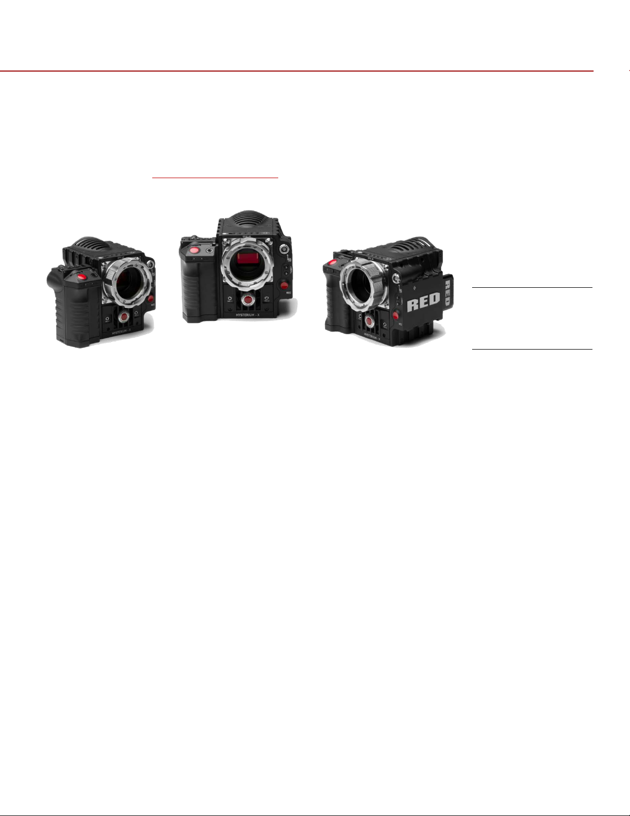
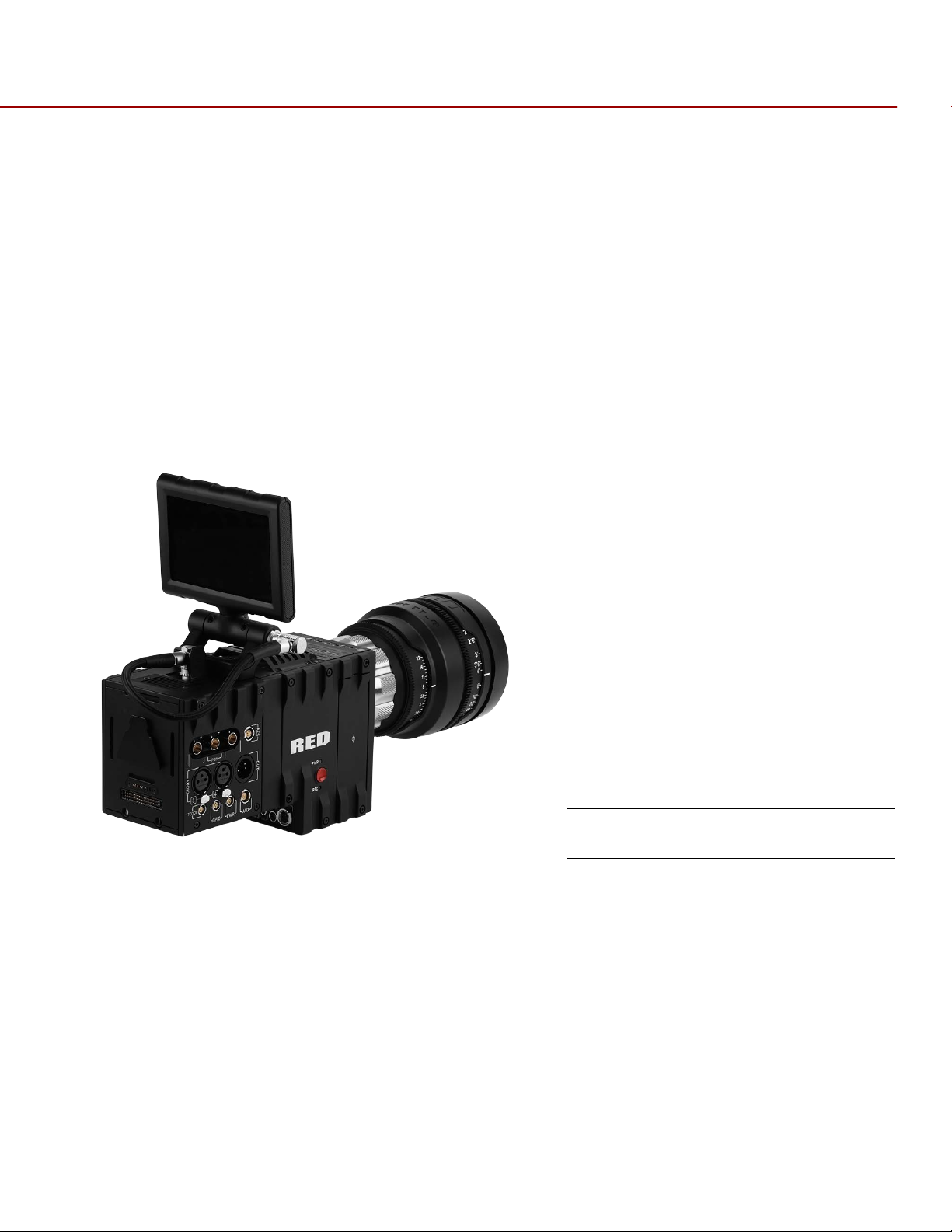
Congratulations on your purchase of a RED DSMC® Digital Still and Motion Camera.
Please read the attached safety instructions, and only then unpack the camera body and any accessories. If
there is any physical damage or missing components for either your camera body or any accessories, please
file a support ticket at
www.RED.com/support
.
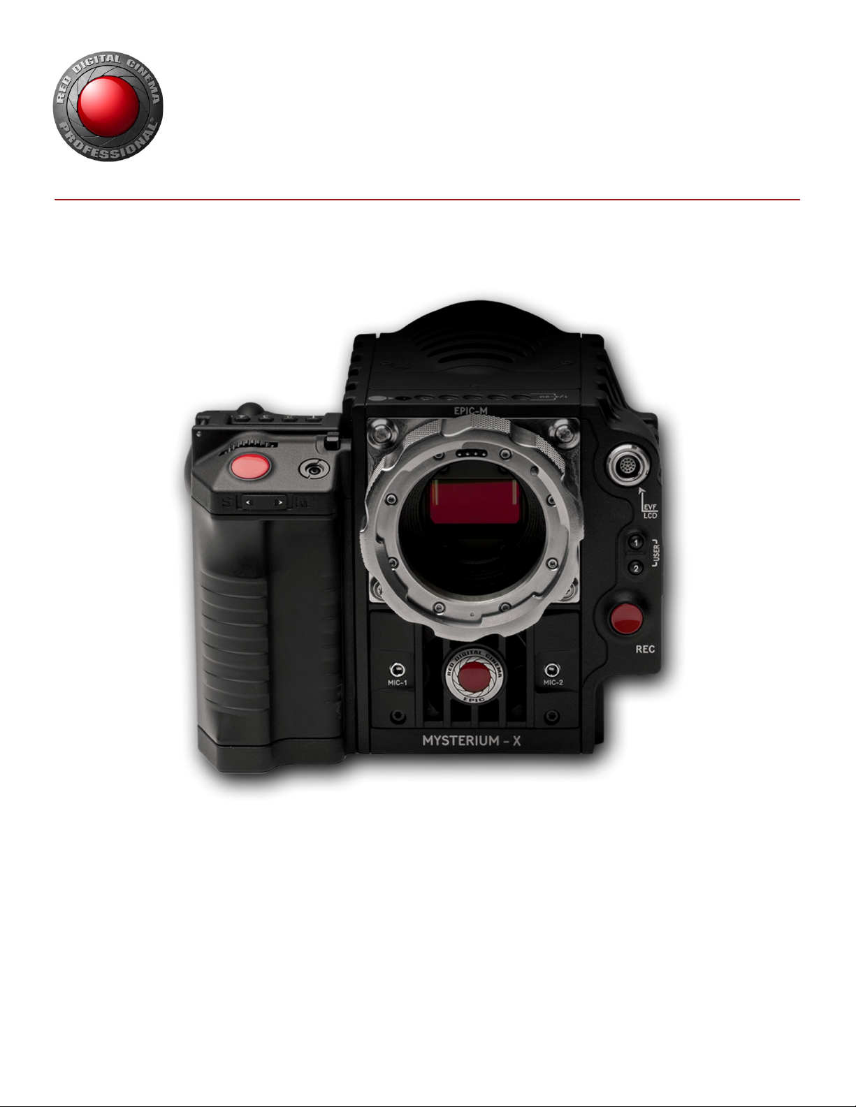
RED EPIC Digital
Still and Motion
Camera
IMPORTANT SAFETY INSTRUCTIONS
READ BEFORE USING YOUR CAMERA
A. Heed all cautions and warnings in these instructions.
B. Read these instructions before operating the camera and accessories.
C. Follow these instructions while operating the camera and accessories.
D. Keep these instructions with the camera and accessories at all times.
E. DO NOT attempt to modify, dismantle or open your camera, lens or other accessory as doing so may
expose you to electric shock and serious injury. There are no user-serviceable parts inside. Alteration or
repairs made to the camera, lens or other accessory, except by a RED authorized service facility, will
void the Limited Warranty. Users are not permitted to make design changes or otherwise modify the
operation of the camera, lenses or other accessories, without the express written approval of RED
DIGITAL CINEMA.
F. Only use attachments/accessories specified by RED.
G. Install camera and accessories in accordance with the manufacturer’s instructions.
H. Avoid imaging of laser beams as they may cause damage to the sensor.
I. DO NOT use the camera or accessories near water. Avoid exposing your camera to moisture. The unit is
not waterproof, so contact with water could cause permanent damage to the unit as well as electric
shock and serious injury to the user. DO NOT use the camera in the rain or under other conditions with
high moisture without appropriate protection, and immediately remove power source if camera or
accessories are exposed to moisture.
WARNING: To reduce the risk of fire or electric shock, do not expose the camera or accessories to rain or
moisture.
COPYRIGHT © 2013 RED.COM, INC
955-0002_v4.0, Rev-A | 10

RED EPIC OPERATION GUIDE
J. DO NOT expose your camera to excessive vibration or impact (shock). Be careful not to drop your
camera. Internal mechanisms may be damaged by severe shock. Mechanical alignment of optical
elements may be affected by excessive vibration.
K. ELECTROMAGNETIC INTERFERENCE: The use of devices using radio or other communication waves
may result in the malfunction or interference with the unit and/or with audio and video signals.
L. Clean only using a dry cloth. When cleaning your camera, remember that it is not waterproof and
moisture can damage electronic circuitry. DO NOT rinse or immerse any element of the camera, lens or
other accessory, keep them dry at all times. DO NOT use soaps, detergents, ammonia, alkaline cleaners,
and abrasive cleaning compounds or solvents. These substances may damage lens coatings and
electronic circuitry.
M. Maintain sufficient ventilation - DO NOT block any ventilation openings or obstruct cooling fan airflow.
CAUTION: Proper camera ventilation requires a minimum 1/2” (1,25cm) clearance between the camera
ventilation openings and external surfaces. Verify that objects that can block the fan intake and exhaust
ports do not impede airflow. Failure to permit adequate airflow may result in overheating of the camera,
degraded operation and in extreme situations, damage to the camera.
N. DO NOT operate or store near any heat sources such as radiators, heat registers, stoves, or any other
apparatus that produce heat. Store in a protected, level and ventilated place. Avoid exposure to
temperature extremes, damp, severe vibration, strong magnetic fields, direct sunlight or local heat
sources during storage. Remove any batteries from the camera before storage. Recommended storage
and usage temperatures for your camera, lenses and other accessories are:
Operating range: 0°C to +40°C (32°F to 104°F)
•
Storage range: -20°C to +50°C (-4°F to 122°F)
•
If there are any performance issues with your camera or accessories when operating within this
temperature range, please file a support ticket on
O. The Side Handle, Side SSD Module, Rear Modules and Lens Mount are NOT HOT SWAPPABLE –
meaning you cannot remove or install them while the camera is powered on. Before installing or
removing any of these accessories, you MUST power down the camera. Failure to do so may result in
damage to the accessory and / or camera brain that will not be covered under warranty.
P. Do not bypass the third prong of the grounding-type plug on the power cord of the AC Power Adapter. A
grounding-type plug has two blades and a third “grounding” prong. The third prong is provided for your
safety. A grounding-type plug shall be connected to an outlet with a protective earthen connection. If the
grounding-type plug does not fit into your outlet, do not attempt to modify the plug or outlet, consult a
qualified electrician.
Q. Protect all power cords from being pinched, walked on or driven over by a vehicle. Replace any power
cords suspected of sustaining damage due to crushing or other forms physical damage.
CAUTION: The power cord plug for the AC Power Adapter is used as the power disconnect. To disconnect
all power from the AC Power Adapter, unplug the power cord plug from the wall outlet. During use, the
power cord plug should remain easily accessible at all times.
R. Lithium Ion batteries may be subject to special handling requirements pursuant to federal and local laws.
Please refer to specific shipping instructions included with your battery regarding proper transport of
your battery. Do not handle your battery if it is damaged or leaking. Disposal of batteries must be in
accordance with local environmental regulations. For example, California law requires that all
rechargeable batteries must be recycled by an authorized recycle center. Storing batteries fully charged
or in high temperature, conditions may permanently reduce the life of the battery. Available battery
capacity may also be temporarily lessened after storage in low temperature conditions.
www.RED.com/support
.
WARNING: Do not expose the battery to excessive heat.
COPYRIGHT © 2013 RED.COM, INC
955-0002_v4.0, Rev-A | 11

RED EPIC OPERATION GUIDE
WARNING: Danger of explosion if an incorrect battery is charged with the RED Charger or is used to power
the camera and accessories. Replace only with the same or equivalent type battery.
CAUTION: Refer all service and repair to qualified RED service personnel. To reduce the risk of electric
shock, and damage to the camera or accessories, DO NOT attempt to perform any servicing other than any
procedures that are recommended in the operating instructions.
COPYRIGHT © 2013 RED.COM, INC
955-0002_v4.0, Rev-A | 12

RED EPIC OPERATION GUIDE
THEORY OF OPERATION
The RED family of Digital Still and Motion Cameras (DSMC) provide high performance digital imaging over a
wide range of frame rates and optical formats including Super 35mm / APS-H. The RED DSMC camera is
supplied as standard with a PL mount, and may be configured with mounts and 19 mm rods to
accommodate most cinematography lenses, matte boxes and follow focus systems. Adaptors for 15mm
offset studio and 15mm lightweight rods are also available.
In addition to compatibility with the majority of existing PL mount cinematography lenses; a select range of
Super 35mm PL mount prime and zoom lenses are available from RED.
Other lens mounts, including the DSMC Canon mount are available, permitting the use of Canon EF and EFS photographic lenses. The Canon mount can report lens iris, focus and zoom data when mated to an
appropriate lens. In addition, iris and manual or auto-focus settings may be controlled from the camera.
Lens mounts may be exchanged in the field, however it is highly recommended that this be performed in a
dust-free environment, as the optical path will be exposed to the elements during this process.
A B4 mount to PL mount adaptor is also available to permit use of 2/3” HD broadcast lenses on the RED
DSMC camera. The optical coverage it provides is approximately equivalent to 16mm, hence the maximum
recording resolution operating with a B4 mount 2/3” lens is 2K (2048 x 1152 pixels) progressive scan.
MYSTERIUM X® SENSOR
The MYSTERIUM X sensor has been specifically designed for use with the RED DSMC camera, and provides
variable frame rate imaging at up to 120fps at 5K resolution, and up to 240 fps at 2K resolution.
Native color balance for the MYSTERIUM X sensor is 5,000 KELVIN, but it may be electronically
compensated for any color temperature in the range 1,700 to 10,000 KELVIN. White balance preset values
include Tungsten (3200K) and Daylight (5600K) light sources. The camera may also calculate a color
neutralizing White Balance value on demand by imaging on a standard white or 18% grey card.
The MYSTERIUM X sensor includes high precision analog to digital conversion, capable of delivering up to
13.5 stops of dynamic range with daylight light sources over a camera sensitivity rating of 320-800 ISO. In
HDR mode, dynamic range can be extended to approximately 18 stops.
IMAGE PROCESSING
The digital image received from the sensor is formatted as a pixel defect corrected (but in all other aspects
unprocessed) 12-bit, 14-bit or 16-bit per pixel RAW data frame.
Each RAW frame or sequence of RAW frames in a clip is compressed using proprietary wavelet based
®
REDCODE
When recorded, the RAW data is independent of any RGB domain color processing such as ISO, White
Balance or other RGB color space adjustments made by the camera operator. These parameters are saved
with the RAW data as reference METADATA; i.e. color is not burned into the recorded RAW data.
RAW compression, then stored to a digital media Magazine such as REDMAG™ 1.8” SSD.
This recording technique permits RGB color processing choices to be deferred to post-production or to be
adjusted in the field to help a director visualize alternative color treatments, without affecting the recorded
RAW data’s image quality or dynamic range.
COPYRIGHT © 2013 RED.COM, INC
955-0002_v4.0, Rev-A | 13

RED EPIC OPERATION GUIDE
The camera’s monitoring path converts RAW sensor data to a white balanced 12-bit depth 2048 x 1080 pixel
RGB 4:4:4 video signal. This signal may be modified using ISO, White Balance or other RGB color space
adjustments as desired by the operator, and is then scaled and gamma corrected to provide VIEWFINDER,
HD-SDI and HDMI monitor outputs at 10-bit depth in 4:2:2 YCC or 8-bit depth in 4:4:4 RGB.
Frame guides and other camera data may be added as desired by the user to one or more of the outputs.
NOTE: The supplied REDCINE-X® PRO application software can create and export .RMD “color look” files
which may then be imported as camera monitor path color processing PRESETs. This information is stored
as reference metadata, so that this color processing choice can be the default value used in Postproduction. Refer to SECONDARY MENUS > PRESETS for details how to import and apply .RMD file
metadata.
HDRX™
HDRx is an option for extending dynamic range up to 6 stops over the base Dynamic Range offered by the
camera. When enabled HDRx simultaneously shoots two images of identical resolution and frame rate - a
normally exposed primary track (A-track), and an underexposed secondary track (X-track) whose exposure
value reflects the additional stops of highlight protection desired.
For example, if you select an HDR value of +2 and your primary track exposure is 1/48th sec, the secondary
track exposure will be 2 stops under, or 1/192 sec. The ISO and Aperture remain the same for both
exposures.
During acquisition and recording, the two tracks are "motion-conjoined", meaning there is no gap in time
between the two exposures. This is very important to note because if they were traditional alternating
exposures, there would be a time gap between the two tracks that would show up as an undesirable motion
®
artifact. Both tracks (A & X) are stored in a single .R3D
Since there are two exposures in HDRx mode, the camera is recording double the amount of frames each
second. For example, when shooting at 24fps, the camera is recording two 24fps tracks, which is the data
rate equivalent of 48fps; however after combining the A and X tracks in post-production you will see only
one 24fps blended image sequence.
HDRx provides multiple options for exploitation in post-production.
Blend the two tracks in post tools like REDCINE-X, Storm or any other application that supports the SDK to
create Magic Motion™. This blending of the two tracks comes with a slider so you can decide just how much
of each track you want to use. A preview window shows you the combined result of your selection, or you
can view each track individually.
Combine the two tracks using MNMB (More Normal Motion Blur). MNMB is designed to emulate the motion
of a traditional camera with full motion blur. This is a tool created by The Foundry that uses a new motion
estimation algorithm designed specifically for HDRx. The shorter exposure (sharper image) is blended to
match the motion blur of the normal exposure. Again, a preview window shows the combined result of your
selection, or you can view each track individually.
file.
Use the X-track data for motion tracking, then combine the X-track with the A-track, or just motion stabilize
the A-track using the motion analysis data extracted from the X-track.
Exporting to EXR file format will give you a multi-view EXR with both exposures (like a stereo EXR).
COPYRIGHT © 2013 RED.COM, INC
955-0002_v4.0, Rev-A | 14

RED EPIC OPERATION GUIDE
NOTE: If you ignore the X-track data, you will have a standard exposure with up to 13.5 stops of dynamic
range just as if you had not enabled HDRx. For this reason, we encourage the A-track exposure to be
"normal" as it provides the most options. If you are tempted to shoot "over-under", you are then fully
committed to using HDRx and your post-production options are reduced.
NOTE: When recording in HDRx mode the camera records twice as many frames per second so the
maximum frame rate or minimum REDCODE ratio, and the maximum record time on your media will be cut in
half.
NOTE: HDRx mode can be used with sensor syncing.
MAGIC MOTION™
Shooting at 24fps and with an 180 degree (1/48th) shutter on a film or digital camera may create an optical
illusion we are familiar with, however it is not really the way the eye sees motion. To understand this, ask
someone to stand in front of you and swing their arm over their head from one side to the other. What you
would observe in the recording is a constant motion blur until the arm stopped. What your eye sees though
is both motion blur AND a sharper reference to the arm and hand all along the motion path. "Magic Motion"
provides such a combination of motion blur (A-track) and a sharper reference (X-track), with the bonus of
extreme dynamic range not available with any other motion capture camera system.
AUDIO RECORDING
The RED DSMC camera can record up to two discreet channels of microphone level uncompressed 24-bit,
48 KHz audio (four channels of microphone level or line level audio inputs when equipped with a PRO I/O
Module), that are synchronized with video and timecode to a REDMAG 1.8” SSD digital media Magazine.
Input signals are routed via a high quality pre-amplifier and soft clip analog limiter in order to achieve the
desired audio reference / recording level and maximize dynamic range.
To assist with audio reference level setup, the camera provides a color-coded Audio Level Meter in the
Graphical User Interface. Meter range is –36dBu to +20dBu (-56dBFS to 0dBFS) with audio input type,
reference level and audio input clipping indicators.
Audio monitor output options include a 2-channel headphone output on the camera Brain and 2-channel line
level analog outputs from the optional PRO I/O Module, plus 2-channel and 4-channel 24-bit 48KHz
uncompressed digital audio embedded in the HD-SDI and HDMI outputs.
MICROPHONE LEVEL ANALOG INPUTS
The recording level of a Microphone input is affected by the sensitivity of the microphone and the Gain
setting of the camera’s pre-amplifier. Available pre-amplifier range is+30dB to +60dB. The camera operator
should choose a Gain value that aligns the input signal to the 0dBu reference line drawn on the camera’s
Audio Level Meter (or the 0VU reference line if operating at that level).
This setting provides up to 30dB of input signal headroom above reference 0dBu level before clipping (up to
26dB above 0VU reference level) and maximizes the signal to noise ratio of the 24-bit digital recording.
COPYRIGHT © 2013 RED.COM, INC
955-0002_v4.0, Rev-A | 15

RED EPIC OPERATION GUIDE
LINE LEVEL ANALOG INPUTS
The recording level of a Line input is affected only by the signal provided by the field production sound
mixer or other external line level source. The sound mixer operator should choose a mixer output level that
aligns a reference tone signal to the 0dBu (-20dBFS) reference mark drawn on the camera’s Audio Level
Meter, or if using 0VU as reference level, a mixer output level that aligns a reference tone signal to the 0VU
(-16dBFS) reference mark.
This setting provides up to 24dB of input signal headroom above reference 0dBu level before clipping (up to
20dB above 0VU reference level) and maximizes the signal to noise ratio of the 24-bit digital recording.
VIDEO MONITORING OUTPUTS
In its default configuration, the RED DSMC camera can simultaneously support one VIEWFINDER output
®
(suitable for use by a BOMB EVF
(suitable for use by HDMI or HD-SDI monitors). The various monitor outputs can support a set of overlay
graphics including camera GUI, timecode, clip name and framing guides; the specific overlay graphics for
each type of output is user configurable.
The default VIEWFINDER output is the EVF / LCD connector located on the front face of the Side SSD
Module. If neither of these is connected, the VIEWFINDER output can be transferred to either the HDMI
output or the HD-SDI output of the camera Brain.
, or RED LCD) plus one PROGRAM output and one PREVIEW output
All monitors are able to display a variety of features, including:
Surround View™, which is an additional look around area, visible outside of the recorded image.
Frame Guides, showing common film presentation and television aspects such as 2.40:1 and 16:9.
Focus, aided by high display resolution, 1:1 Focus Check function and False Color overlay.
Exposure, aided by dual Zebras, False Color overlay, RAW “Traffic Lights” and RGB histogram.
System information including current frame rate, ISO rating, shutter speed, color temperature, record
resolution, record quality, clip name, timecode value and the remaining battery and media capacity.
COPYRIGHT © 2013 RED.COM, INC
955-0002_v4.0, Rev-A | 16
RED EPIC OPERATION GUIDE
BOMB EVF
The BOMB EVFs are high-definition, lightweight viewfinders that align quality performance with compact
form factor.
For applications where use of an attached RED EVF or RED LCD is not desired – for example when working
on a crane – the VIEWFINDER / MENU output can be transferred to the HD-SDI or HDMI outputs, supporting
remote camera monitoring up to 200 ft away.
RED TOUCH LCD
The RED TOUCH LCD pixel progressive scan color displays allow you to view your image and navigate
through menu settings using touchscreen functionality.
For applications where use of an attached RED EVF or RED LCD is not desired – for example when working
on a crane – the VIEWFINDER / MENU output can be transferred to the HD-SDI or HDMI outputs, supporting
remote camera monitoring up to 200 ft away.
HD-SDI
A 720p or 1080p progressive scan output suitable for monitoring or recording to an external VTR or DDR
device. May be configured for 10-bit LIN (VIDEO) or 10-bit LOG (FILM) encoded data.
HDMI
A 720p or 1080p progressive scan output suitable for monitoring via a PC monitor or most HDTV displays.
Example of HDMI Monitor Output in
MENUS Mode
COPYRIGHT © 2013 RED.COM, INC
955-0002_v4.0, Rev-A | 17
RED EPIC OPERATION GUIDE
REDMOTE®
REDMOTE is a camera control unit for RED’s family of DSMC cameras that attaches to the rear of the
camera Brain or rearmost expansion module. REDMOTE may also be detached from the camera or rearmost
module and provide wireless remote control of the camera over proprietary REDlink™ protocol.
Whether attached or operating via wireless, REDMOTE supports all controls necessary to operate the
camera, including Record Start / Stop, Shutter Speed, White Balance, ISO and programmable User Keys. A
color LCD displays critical camera parameters, including media and battery capacity, timecode and clip
name, lens data and exposure information.
REDMOTE LCD Display
REDMOTE includes a rechargeable Li-Ion battery, which automatically re-charges when attached to the
camera or rearmost module. It may also be re-charged by connecting to a USB 2.0 based power source
such as a laptop PC or cell phone charger. Under typical operating conditions, REDMOTE should operate for
up to 8 hours without requiring a re-charge and support a wireless communication range of approximately 50
ft.
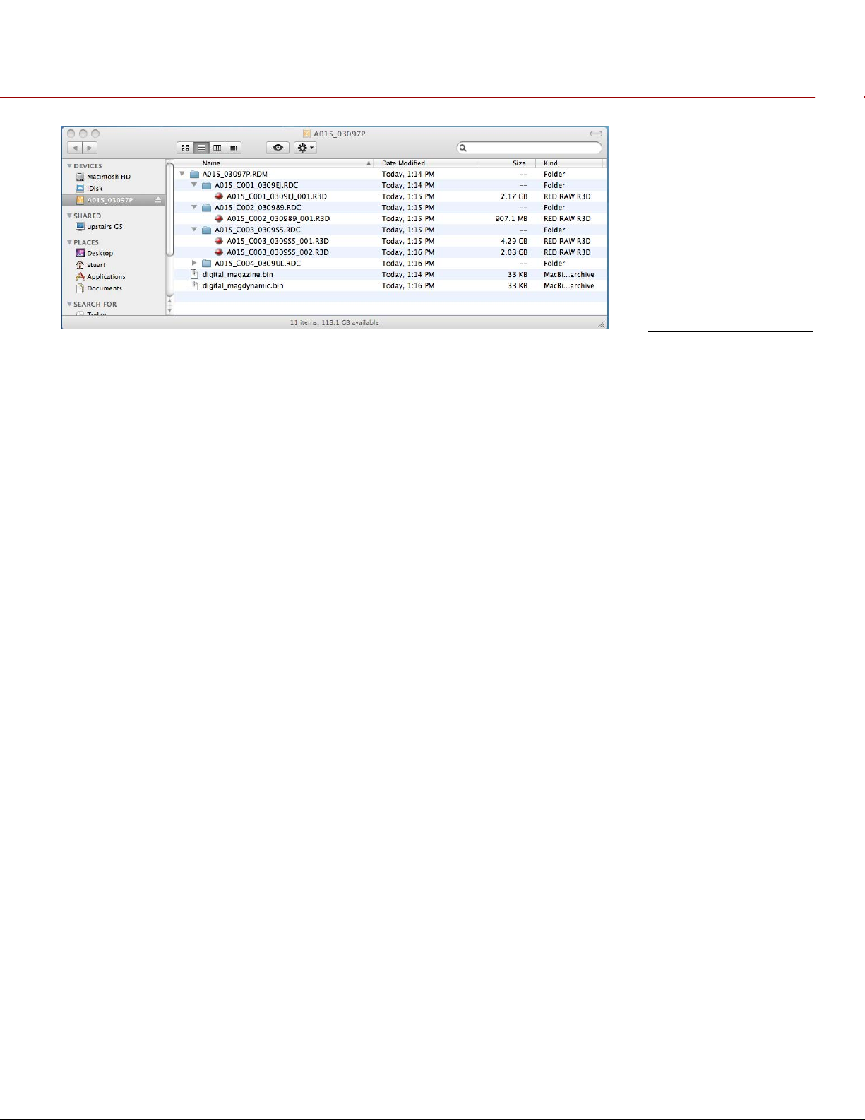
DIGITAL MAGAZINE (MEDIA)
REDCODE RAW compressed MOTION clips and STILL images; time code, multi-channel audio and metadata
may be recorded to a
Each clip is recorded with a unique name in a clip folder with the extension .RDC. This folder contains all
appropriate information describing the clip, including one or more REDCODE RAW .R3D files and all color
grading metadata and other system level metadata such as lens and location information. Refer to
NAMING CONVENTIONS.
The individual clip folders are placed into a magazine folder (i.e. root directory) on the digital media. This
magazine folder has the extension .RDM. As this folder contains all the recorded clips; copying all clips
recorded on the SSD to other media may be performed by a drag and drop operation on the .RDM folder.
NOTE: When using a RED STATION in conjunction with a 512GB REDMAG, an AC Power Adaptor will be
required for offload. The RED STATION may not function properly when powered by a USB or Firewire
cable.
REDMAG 1.8” SSD
magazine of 64GB, 128GB, 256GB, or 512GB capacity.
CLIP
COPYRIGHT © 2013 RED.COM, INC
955-0002_v4.0, Rev-A | 18
RED EPIC OPERATION GUIDE
Typical Magazine
Folder and Clip
Structure
For additional information about digital magazines, refer to APPENDIX B: MANAGING DIGITAL MEDIA.
METADATA
RED’s family of DSMC cameras record the Metadata, which is data for each frame of the recording:
Clip Name
Time Code
Date and GMT
Lens and shutter speed /
angle parameters
Audio configuration
Firmware version #
media serial #
LTC user bits (3 32-bit word
reg-dump from ISP)
s4i static data
s4i dynamic data
GMT time/data
RGB curves
shadow control
Luma curve
Lens name, brand, ID, near
focus, far focus
Camera Network Name
Production Name
Director Name
DP Name
Copyright
Unit
Camera Name
Location
Scene
Take
Accelerometer Data
Gyro Data
COPYRIGHT © 2013 RED.COM, INC
955-0002_v4.0, Rev-A | 19

RED EPIC OPERATION GUIDE
CLIP NAMING CONVENTIONS
When you press RECORD, the camera automatically creates a unique name for the CLIP being recorded to
the REDMAG 1.8” SSD media. The format of this name is:
Camera Letter + Reel Number + Month + Day
e.g. A001_C002_0502**.RDC
Where: A = camera A, 001 = reel 001, C002 = clip 002, and 0502 = May 02, and the digits * * are two random
characters generated by the camera to prevent any possibility of duplicate names being created.
So a three Clip sequence of Clip Folders within a Magazine Folder on Camera A would look like this:
A001_C001_0502**.RDC A001_C002_0502**.RDC A001_C003_0502**.RDC
MULTI CAMERA SHOOTS
The scheme provides flexibility to uniquely identify Clips from different cameras on a multi-camera shoot.
For example three cameras, slated as camera A, camera B, and camera C respectively, can generate these
easily recognizable clips on their respective digital media Magazines.
A001_C001_0502**.RDC B001_C001_0502**.RDC C001_C001_0502**.RDC
3D (STEREO) CAMERA SHOOTS
The scheme also allows unique identification of Clips from left and right eye cameras on a stereo shoot.
For example two cameras, both slated as Camera S, can generate these easily recognizable clips on their
respective digital media Magazines.
S001_L001_0502**.RDC S001_R001_0502**.RDC
For more information refer to APPENDIX F: 3D SETUP / OPERATION > CLIP NAMING CONVENTIONS.
SMPTE TIMECODE
Time Code (TC) is a SMPTE timecode track that synchronizes to the camera’s high precision internal clock,
or if operated in Jam Sync mode, references to an externally supplied SMPTE master timecode signal. TC is
a sequential code that is continuous from frame to frame, but is discontinuous from clip to clip.
Edge Code (EC) is a SMPTE timecode track that always starts at 1.00.00.00 on the first frame recorded to
the digital media. It is a sequential code that is continuous from frame to frame and also continuous from
clip to clip. EC is equivalent to RUN RECORD commonly found on broadcast cameras.
Irrespective of the timecode mode selected, once recording starts the camera’s timecode counter will
update at the same instantaneous frame rate as the recording. This ensures that a valid SMPTE timecode
value is created for every frame in the clip, eliminating any timecode count jumps that could affect playback
or editing.
If operating in Jam Sync mode referenced to an external timecode source, the clip’s master time reference
point is the first frame of the recorded clip.
COPYRIGHT © 2013 RED.COM, INC
955-0002_v4.0, Rev-A | 20
RED EPIC OPERATION GUIDE
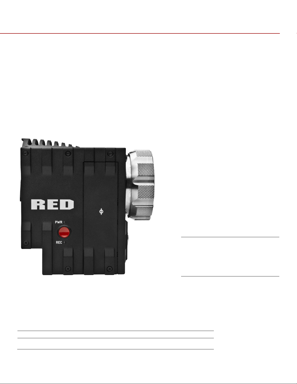
EPIC BRAIN
Power Status LED
Indicates Power Status:
Power/Record Button
Powers Camera Up / Down and Indicates Record Stop / Start
Record Status LED
Indicates Record Status:
A
C B
POWER CONSUMPTION
The camera draws approximately 60 watts when recording in 5K resolution, 24fps MOVIE mode. The camera
is cooled by convection from the camera body assisted by a fan contained in a sealed air duct.
®
Under typical operating conditions, a REDVOLT
®
minutes and a REDVOLT
XL battery will run the camera and accessories for about 90 minutes.
CAMERA OPERATIONAL CONTROLS
This section describes the available operational controls on the RED DSMC camera Brain, Side SSD Module,
Side Handle and REDMOTE accessories.
BRAIN
battery will run the camera and accessories for about 30
A. Power Status LED
B. Power/Record Button
C. Record Status LED
LED Red = Power Present, Camera OFF
LED Yellow = Power Present, Camera Booting
LED Green = Power Present, Camera ON
LED Green Blinking = Power Present, Running on Battery
LED Yellow Blinking = Power Present, 5-10 Minutes of Battery Time
Left
LED Red Blinking = Power Present, Less than 5 Minues of Battery
Time Left
LED Off = No Media Present
COPYRIGHT © 2013 RED.COM, INC
955-0002_v4.0, Rev-A | 21
RED EPIC OPERATION GUIDE
LED Green = Ready to Record
Both LEDs
Indicates Camera Status:
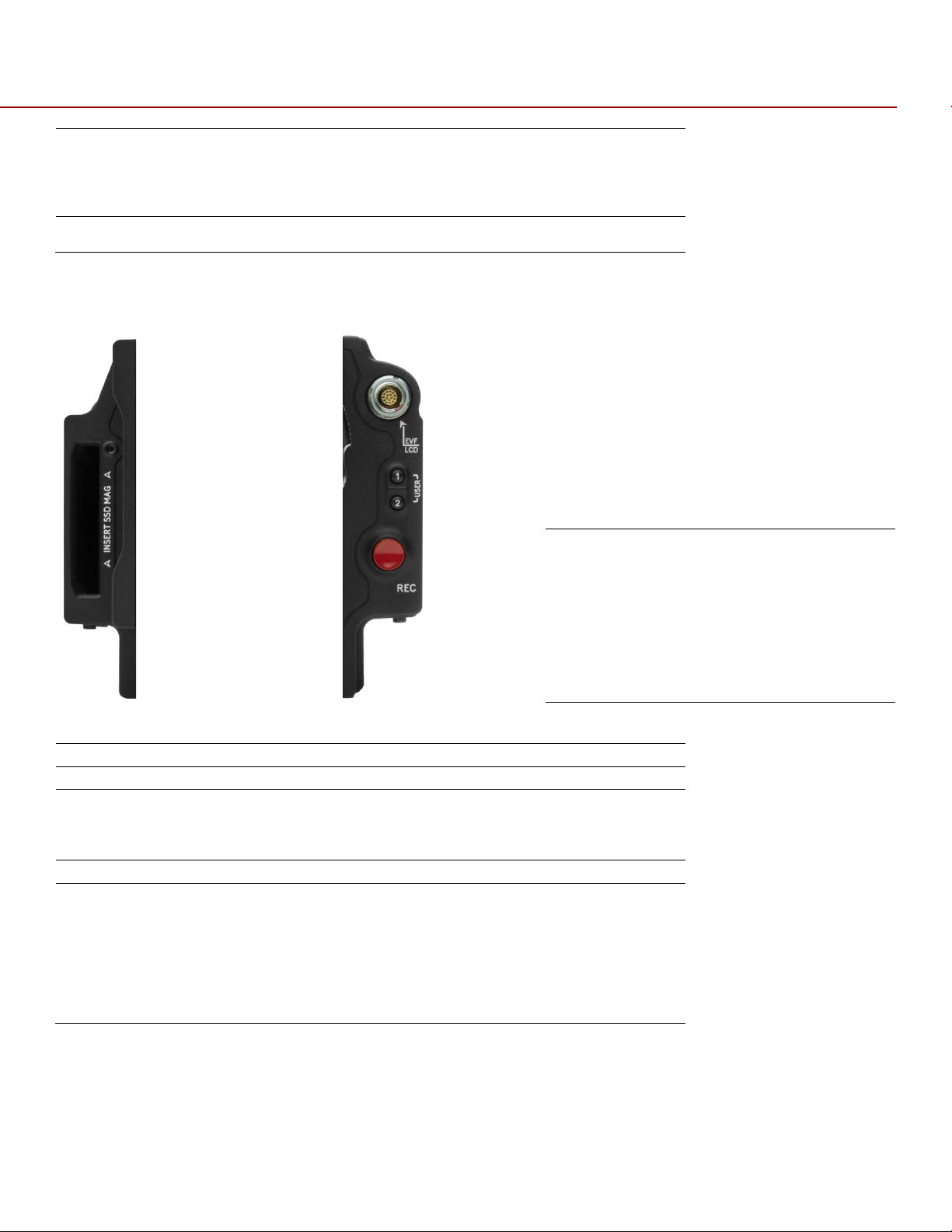
Side SSD Module
SSD Slot
Slot for REDMAG 1.8” SSD Digital Media Magazine
S-SSD User Key 1
Initiates User Defined Camera Function. Undefined by Default
S-SSD User Key 2
Initiates User Defined Camera Function. Undefined by Default
S-SSD User Key 1 + 2
The specific function of pressing these keys may be programmed by
Focus/Record Button
Touch for Auto Focus, Fully Depress to Start or Stop Record
Media Indicator LED
Indicates Status of Media:
FRONT
REAR
A
B
C
D E
LED Red Constant = Recording
LED Red Slow Blink = Recording, 25% Media Left
LED Red Fast Blink = Recording, 5% Media Left
LED Yellow = Finalizing
Both LEDs Green Blink = Firmware Update in Progress
SIDE SSD MODULE
A. SSD Slot
B. S-SSD User Key 1
C. S-SSD User Key 2
D. Focus/Record Button
E. Media Indicator
the user.
By default, press both keys to Eject (Unmount) REDMAG 1.8” SSD
Magazine
LED Off = No Media
LED Green = Ready to Record
LED Red Constant = Recording
LED Red Slow Blink = Recording, 25% Media Left
LED Red Fast Blink = Recording, 5% Media Left
LED Yellow = Finalizing
LED Yellow Blinking = Media Access (Format etc…)
COPYRIGHT © 2013 RED.COM, INC
955-0002_v4.0, Rev-A | 22
RED EPIC OPERATION GUIDE
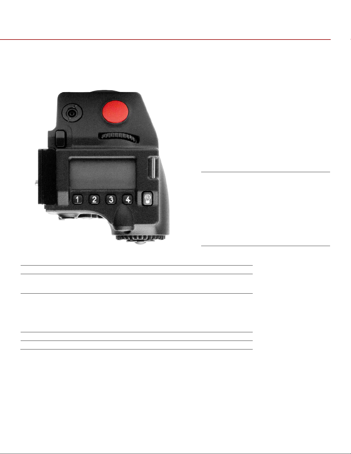
Side Handle - Top
Battery Door Release
Releases Side Handle battery door to permit battery exchange
Focus/Record Button
Touch for Auto Focus, fully depress to Start or Stop Record
Adjustment Ring
Selects and adjusts camera parameter values. Similar to the scroll
SH User Keys 1-4
The specific functions for each key are defined by the LCD screen.
LCD Display
Displays key camera parameter values
LCD Backlight Button
Enables LCD backlight
A
B
C D E F
SIDE HANDLE
TOP
A. Battery Release
B. Focus/Record Button
C. SH Rotary Front
D. SH User Keys 1-4
E. LCD Display
F. LCD Backlight Button
Button
NOTE: Side Handle (SH) controls can be locked/unlocked by holding the 1 and 4 buttons simultaneously.
wheel on the navigation group. Can assign different functions to
clockwise and counter-clockwise directions
Defaults are:
1 = ISO
2 = F-Stop
3 = Shutter Speed
4 = Color Temperature
COPYRIGHT © 2013 RED.COM, INC
955-0002_v4.0, Rev-A | 23
RED EPIC OPERATION GUIDE
Side Handle – Front
Stills/Movie Switch
The specific function of this switch may be programmed by the user.
A
FRONT
A. Stills/Movie Switch
Default settings are as follows:
STILLS = Change focus mode to Still
Movie = Changes focus mode to Movie/Motion
The DSMC has two AF modes: one for stills and one for movies/motion. In Stills mode, you can select a
specific AF setting, and then go to Movie/Motion mode and change your AF setting. By default, the
Stills/Movie Switch toggles between these two AF settings.
COPYRIGHT © 2013 RED.COM, INC
955-0002_v4.0, Rev-A | 24
RED EPIC OPERATION GUIDE
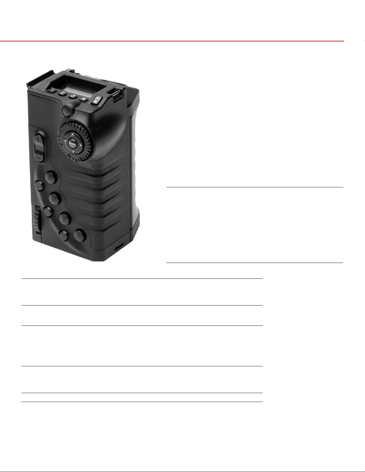
Side Handle – Rear
Menu Button
Press to access / camera setup menus
Rocker Switch
The specific function of these keys may be programmed by the user.
Navigation Group
Allows navigation through camera menus, selection of camera
SH User Keys A-D
The specific function of these keys may be programmed by the user.
SH User Keys 5-7
Function is defined by System Firmware:
Thumbwheel Lock
Locks Side Handle in position on camera
A B C
D
E F
REAR
A. Menu Button
B. Rocker Switch
C. Navigation Group
D. SH User Keys A-D
E. SH User Keys 5-7
F. Thumbwheel Lock
Default Settings are as follows:
Rocker Switch+ = Opens Iris
Rocker Switch - = Closes Iris
parameter for adjustment and adjustment of selected camera
parameter
Default settings are as follows:
User Key A = Toggles Focus Assist indicator
User Key B = Performs White Balance calculation
User Key C = Toggles False Color > 1:1 Magnify
User Key D = Toggles False Color > Exposure Check
User Key 5 = Toggles False Color > Exposure Check
User Key 6 = Disabled
User Key 7 = Eject Media
COPYRIGHT © 2013 RED.COM, INC
955-0002_v4.0, Rev-A | 25
RED EPIC OPERATION GUIDE
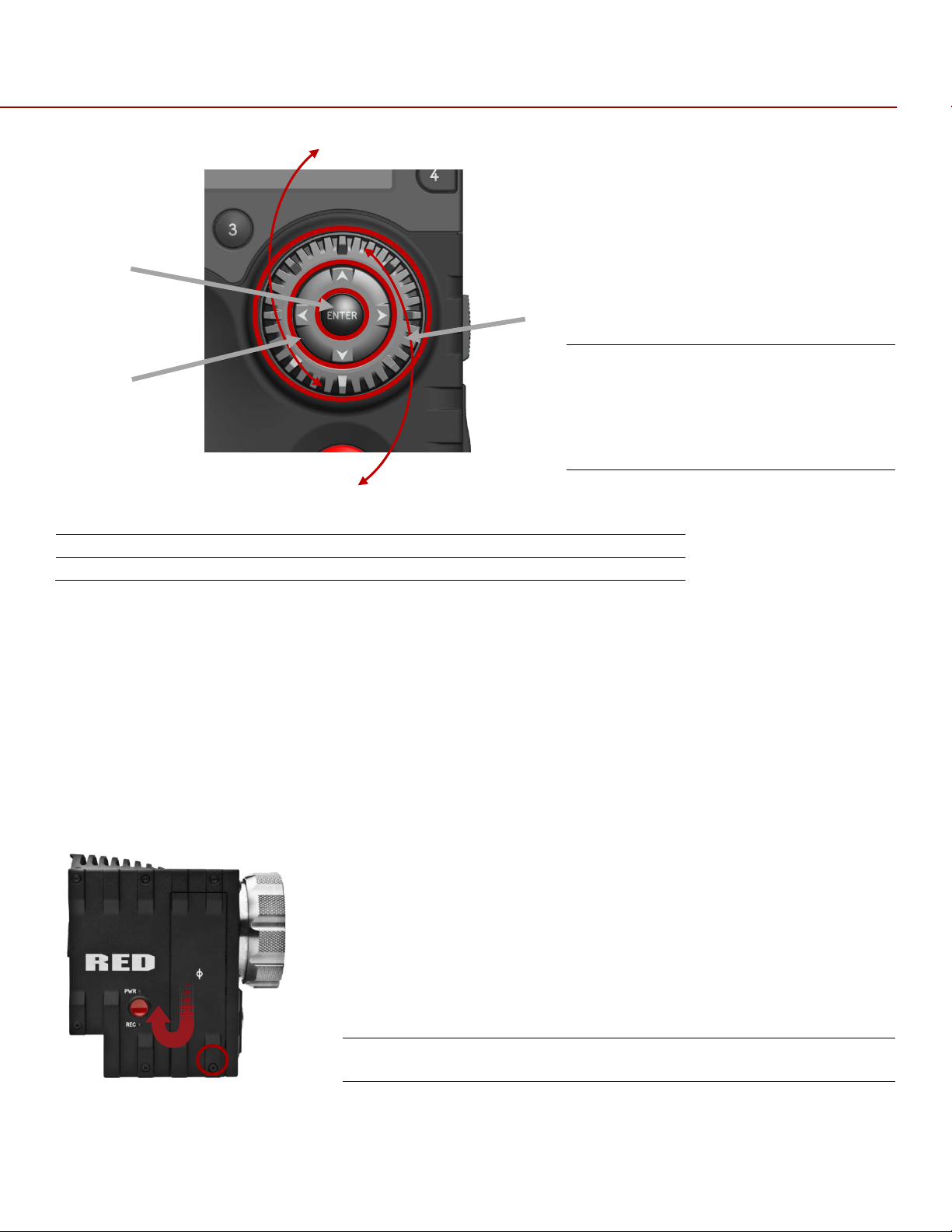
Side Handle Navigation Group
Scroll Wheel
Selects and adjusts camera parameter value
Direction Keys
Navigates camera menus and may select parameter for adjustment
Enter Button
Confirms selected parameter value adjustment
C
B
A
NAVIGATION GROUP
A. Scroll Wheel
B. Direction Keys
C. Enter Button
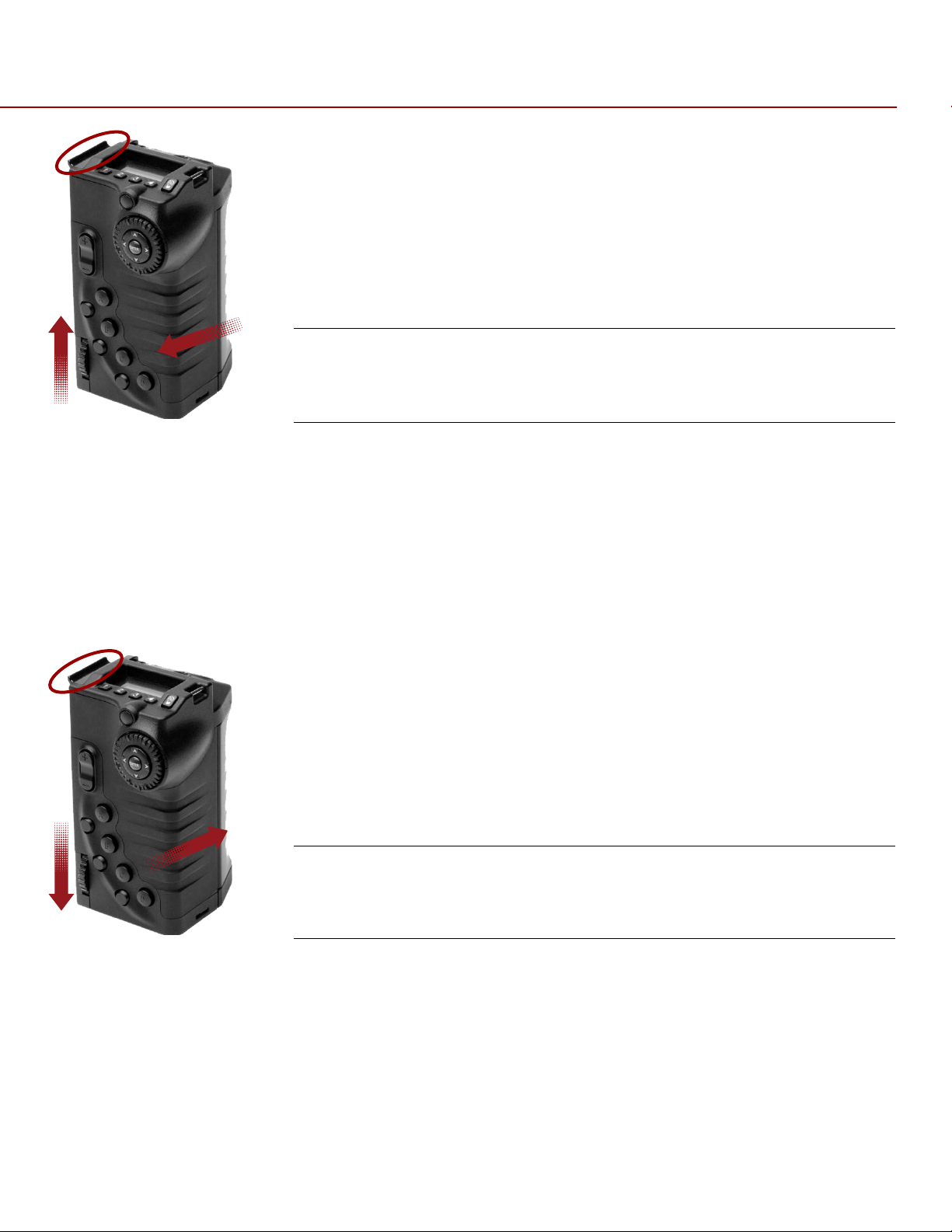
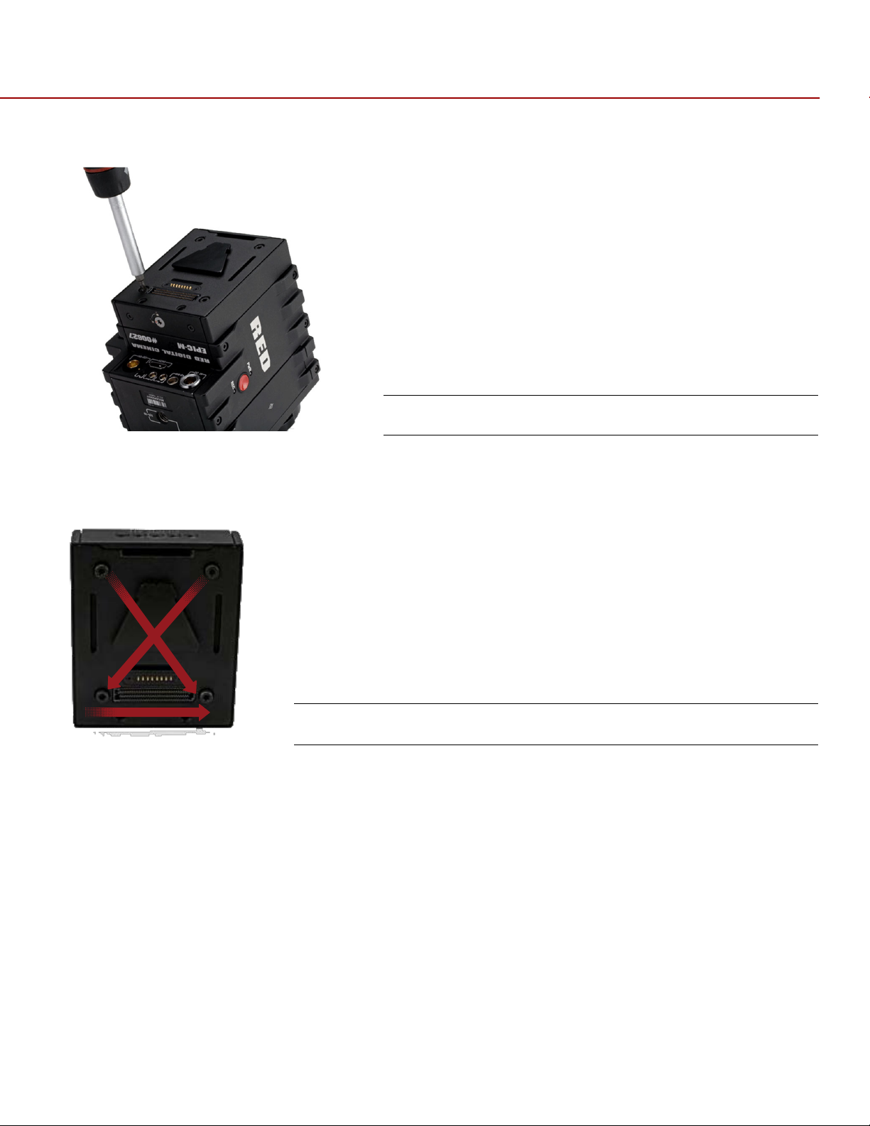
INSTALLATION / REMOVAL
WARNING: The Side Handle is NOT hot swappable - meaning you cannot remove or install while the camera
is powered on. Before installing or removing the Side HANDLE, you MUST power down the camera. Failure
to do so may result in damage to the Side Handle and / or camera brain that is not covered by warranty.
To install the side handle:
1. Power down the camera if necessary.
2. Remove the brain side plate (if installed) by removing the single screw located at the bottom.
3. Rotate upwards to disengage lip at top of side plate from camera brain.
Remove Screw and Rotate Side Plate Upwards to Remove
4. Insert the lip at the top of the side handle into the area where the lip from the side plate was installed.
COPYRIGHT © 2013 RED.COM, INC
955-0002_v4.0, Rev-A | 26
RED EPIC OPERATION GUIDE
Insert Lip into Top of Camera Brain
Press Side Handle Flush Against Camera Brain
Rotate Thumbwheel Upwards Until Tight
5. Rotate side handle down flush along side of camera brain.
6. Rotate thumbscrew upwards until tight. Ensure side handle is secure to camera brain. You may have to
apply steady pressure to get the screw started.
To remove the side handle:
1. Power down the camera if necessary.
2. Rotate the thumbscrew downwards until detached from camera body.
Rotate Thumbwheel Downwards Until Loose
Rotate Side Handle Upwards to Remove
Disengage Lip from Top of Camera Brain
3. Rotate upwards and pull down to disengage lip at top of side handle from camera brain.
4. Remove side handle from camera.
COPYRIGHT © 2013 RED.COM, INC
955-0002_v4.0, Rev-A | 27
RED EPIC OPERATION GUIDE
DSMC MODULES
PRO I/O MODULE
The PRO I/O MODULE brings together the essential I/O connections into one module, providing a central
hub for professional audio and video components.
Centralized ports make it easy to manage connections and cables
LCD/EVF port allows you to connect an additional RED LCD or EVF
Customize triggers and interface with third-party GPIO and RS232 control devices using RED Pro I/O cables
Attach an additional DSMC module or a REDMOTE to the back of the PRO I/O MODULE for additional
expansion
Internal cooling system maintains appropriate operating temperature
Pro I/O Module
COPYRIGHT © 2013 RED.COM, INC
955-0002_v4.0, Rev-A | 28
RED EPIC OPERATION GUIDE
Battery Eject Button
REAR SSD MODULE
The Rear SSD Module secures onto the back of the DSMC brain to serve as a rear location for recording
onto 1.8" REDMAG SSD media.
Rear SSD Module
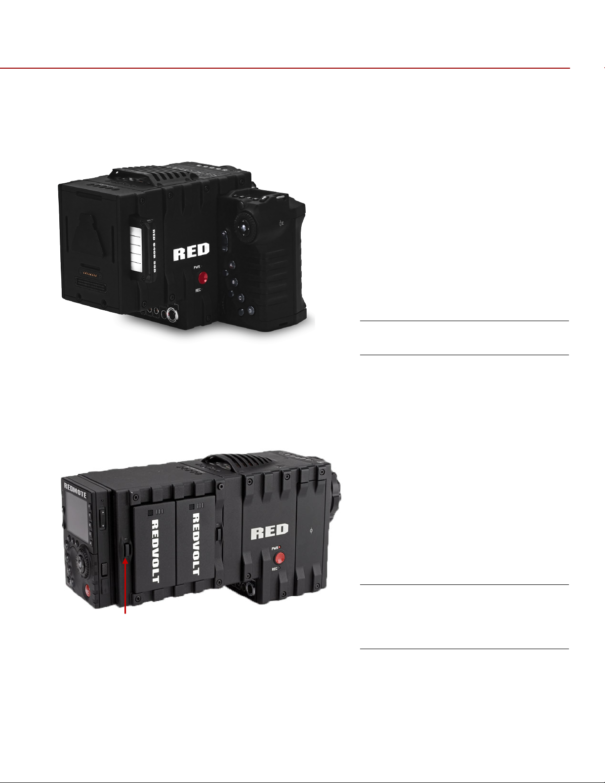
QUAD BATTERY MODULE
The QUAD BATTERY MODULE holds up to 4 REDVOLTs or 2 REDVOLT-XLs
Batteries may be hot swapped
Quad Battery Module
Shown with REDVOLT Batteries
Installed
COPYRIGHT © 2013 RED.COM, INC
955-0002_v4.0, Rev-A | 29
RED EPIC OPERATION GUIDE
DUAL BATTERY MODULE
The DUAL BATTERY MODULE holds up to 2 REDVOLTs
Batteries may be hot swapped
Dual Battery Module
Shown with REDVOLT Batteries
Installed
MODULE INSTALLATION / REMOVAL
To install a DSMC Module to the camera, an Adaptor Plate must be purchased separately. The following
procedure details installation of the Adaptor Plate and DSMC Module.
Install the Adapter Plate
1. Power down the camera.
2. Remove the REDMOTE.
3. Place the adapter plate over the v-mount on the rear of the camera brain.
COPYRIGHT © 2013 RED.COM, INC
Place the Adaptor Plate Over the V-Mount on the Rear
of the Camera Brain
955-0002_v4.0, Rev-A | 30
RED EPIC OPERATION GUIDE
1 2 3 4 1 3
4
2
4. Using a T-20 Torx, lightly tighten the four screws. Do not over tighten.
Tighten Four Screws Do Not Over Tighten
5. Tighten the screws again in a cross pattern until tight.
Tighten Screws Again in a Cross Pattern Until Tight
COPYRIGHT © 2013 RED.COM, INC
955-0002_v4.0, Rev-A | 31

RED EPIC OPERATION GUIDE
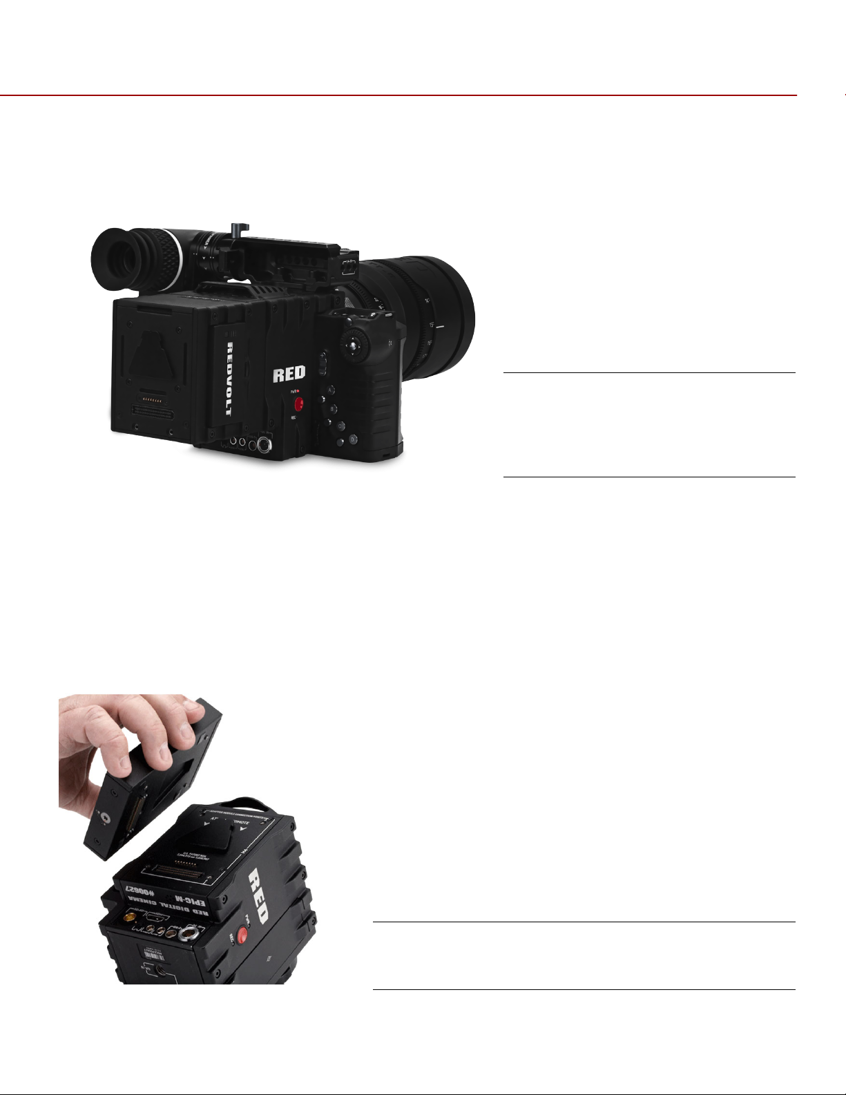
ATTACHING THE DSMC MODULE
WARNING: DSMC Modules are NOT hot swappable - meaning you cannot remove or install while the
camera is powered on. Before installing or removing a Module, you MUST power down the camera. Failure
to do so may result in damage to the Module and / or camera brain that is not covered by warranty.
Quad Battery Module shown.
1. Insert the lip at the top of the module into the recess at the top of the adaptor plate.
Insert Lip at Top of Adaptor Plate
Rotate Module Down Until Flush with Adaptor
2. Rotate module down flush with the rear of the adaptor plate.
Apply Steady Pressure
COPYRIGHT © 2013 RED.COM, INC
955-0002_v4.0, Rev-A | 32

RED EPIC OPERATION GUIDE
3. While applying steady pressure to hold the module against the adaptor plate, use a T-20 Torx
screwdriver to rotate the lock on the adapter plate clockwise to secure the module.
Press Module Flush with Adaptor
Rotate Lock Clockwise Until Red Dot Lines Up with
Lock Icon
4. Installation is now complete.
To remove the DSMC Module and Adaptor Plate:
1. Power down the camera.
2. Use a T-20 Torx screwdriver to rotate the lock on the adapter plate to the Unlock position.
3. Rotate the module upwards and down to disengage lip at top of battery from adaptor plate.
4. Remove module from adapter plate.
5. Use a T-20 to loosen the screws attaching the adaptor plate the camera brain.
6. Remove the adaptor plate from the camera brain.
COPYRIGHT © 2013 RED.COM, INC
955-0002_v4.0, Rev-A | 33

RED EPIC OPERATION GUIDE
REDMOTE
Still/Motion Slider
Allows selection of STILLS or MOVIE operational modes
Release Button (L)
Record LED
Power LED
Rocker Switch
Provides continuous adjustment of parameter specified in USER KEYS
User Keys A-D
Press to initiate camera functions as defined in USER KEY menu.
MENU Button
Press to access / camera setup menus
Soft Menu Keys 1-3
Function is defined on the LCD screen. For complete information refer
Navigation Group
Allows navigation through camera menus, selection of camera
Focus/Record Button
Touch for Auto Focus, fully depress to Start or Stop Record
A B C D
E
G F H
I
K
J
N M L
REDMOTE
This section describes the physical controls on the REDMOTE. For complete details on REDMOTE control,
refer to APPENDIX E: REDMOTE OPERATION.
IMPORTANT: For your REDMOTE to operate with this camera build version, ensure your REDMOTE has
been upgraded to the latest firmware. Refer to APPENDIX E: REDMOTE OPERATION > MAINTENANCE >
UPGRADING REDMOTE FIRMWARE.
A. Still/Motion Slider
B. Release Button (L)
C. Record LED
D. Power LED
E. Rocker Switch
F. User Keys A-D
G. MENU Button
H. Soft Menu Keys 1-3
I. Navigation Group
J. Focus/Record Button
K. Soft Menu Keys 4-8
L. Power/Lock Slider
M. Release Button (L)
N. USB Connector
menu
Default settings are as follows:
User Key A = Toggles Focus Assist Indicator
User Key B = Toggles False Color > RAW Check
User Key C = Toggles False Color > 1:1 Magnify
User Key D = Toggles False Color > Exposure Check
to APPENDIX E: REDMOTE OPERATION > OPERATION > REDMOTE
MENUS > SOFT MENU BUTTONS 1-3
parameter and adjustment of selected camera parameter
COPYRIGHT © 2013 RED.COM, INC
955-0002_v4.0, Rev-A | 34

RED EPIC OPERATION GUIDE
Soft Menu Keys 4-8
For complete information refer to APPENDIX E: REDMOTE
Power/Lock Slider
Slide and hold down for two seconds to power up / down REDMOTE
Release Button (L)
USB Connector
REDMOTE Navigation Group
C B
A
OPERATION > OPERATION > REDMOTE MENUS > SOFT MENU
BUTTONS 4-8
and / or cameras. Slide up to lock keys
NAVIGATION GROUP
A. Scroll Wheel
B. Direction Keys
C. Enter Button
DISPLAYS
BOMB EVF AND BOMB EVF (OLED)
BOMB EVF is a high-definition, lightweight viewfinder that aligns quality performance with compact form
factor.
Resolution: 1280 (wide) x 784 (high) full-color
Contrast Ratio: 1000:1 typical
Available diopter range: +2.0 to -5.0.I
COPYRIGHT © 2013 RED.COM, INC
955-0002_v4.0, Rev-A | 35

RED EPIC OPERATION GUIDE
BOMB EVF
BOMB EVF
A B C
A B C
A. Focus Ring
B. Talley Light
C. Brightness Controls
RED BOMB EVF (OLED) brings advanced OLED technology into the field, providing truer blacks and more
color accurate images
Resolution: 1280 (wide) x 1024 (high) full-color
Contrast Ratio: > 1000:1 typical
Available diopter range: +2.0 to -5.0.I.I
A. Focus Ring
B. Talley Light
C. Brightness Controls
NOTE: The specific function of EVF user keys (B/C) may be programmed by the user.
COPYRIGHT © 2013 RED.COM, INC
955-0002_v4.0, Rev-A | 36

RED EPIC OPERATION GUIDE
Touchscreen LCD – 5” LCD Shown
A
B
C
TOUCHSCREEN LCD
RED offers two touchscreen LCDs, a five-inch model with 800 X 400 resolution and a nine-inch with 1280 X
784. Both feature 4:4:4 progressive scan. The touchscreen LCD allows navigation of camera menus and
selection and adjustment of camera parameters by directly touching icons on the screen. Gestures
supported include:
Tap
Tap on an icon to bring up a quick adjustment display.
:
Double-Tap
Hold:
Touch and hold on an icon to bring up an advanced interface display.
Slide
Pinch:
gesture is disabled.
When a menu or drop-down menu is open, touch and slide to increment a value.
:
Touch with two fingers, then open or close to magnify or normalize the video image. By default, this
If the monitor is in Clean mode, changes to Menus mode.
:
A. User Key 1 1:1 Magnify
B. Backlight Adjust
C. User Key 2 Exposure Check
NOTE: Default functions shown. All keys may be programmed by the user.
CAUTION: When do not use the threaded holes when mounting the display to a RED camera brain. Doing so
may damage the camera or the display.
COPYRIGHT © 2013 RED.COM, INC
Do Not Use Threaded Holes to
Mount LCD to the Camera
955-0002_v4.0, Rev-A | 37

RED EPIC OPERATION GUIDE
BASIC OPERATION
This section describes basic operation, starting from power up, Viewfinder layout and Menu navigation.
WARNING: The Side Handle, Side SSD Module, rear modules and Lens Mount are NOT HOT SWAPPABLE –
meaning you cannot remove or install them while the camera is powered on. Before installing or removing
any of these accessories, you MUST power down the camera. Failure to do so may result in damage to the
accessory and / or camera brain that will not be covered under warranty.
Power draw is prioritized as follows when multiple power sources are available to the camera.
1. DC (Voltage) or Brick (%)
2. Battery Module batteries
3. Side Handle battery
POWER SOURCES
SIDE HANDLE
The optional Side Handle accepts one REDVOLT.
Side Handle Battery Compartment
COPYRIGHT © 2013 RED.COM, INC
955-0002_v4.0, Rev-A | 38

RED EPIC OPERATION GUIDE
QUAD BATTERY MODULE
The optional QUAD BATTERY MODULE accepts up to four REDVOLT or up to two REDVOLT XL batteries,
which can power the camera and typical accessories.
Quad Battery Module
REDVOLT AND REDVOLT XL
REDVOLT and REVOLT XL
NOTE: When multiple batteries are installed in the Quad Battery Module, the power management circuit will
select the lowest charged battery to supply power to the camera. On depletion, a battery may be ejected
from the Quad Battery Module for re-charging, and a new charged battery may be inserted in its place. i.e.
batteries may be hot swapped, there is no need for the operator to power down the camera to replace a
REDVOLT battery when using the Quad Battery Module.
COPYRIGHT © 2013 RED.COM, INC
955-0002_v4.0, Rev-A | 39

RED EPIC OPERATION GUIDE
BACKPACK QUICKPLATE
The optional BACKPACK QUICKPLATE attaches directly to the back of the DSMC BACKPACK to provide a
compact REDBRICK configuration for EPIC or SCARLET-X.
NOTE: DSMC BACKPACK is required for use of the BACKPACK QUICKPLATE.
Backpack Quickplate
REDBRICK
COPYRIGHT © 2013 RED.COM, INC
955-0002_v4.0, Rev-A | 40

RED EPIC OPERATION GUIDE
AC POWER ADAPTOR - (DSMC)
AC Power Adaptor (DSMC)
When powering the DSMC with the A/C Power Adaptor, you can see the incoming voltage and source (DC)
on the lower part of the screen. You can also see the power information in the POWER status menu.
Power Details
In use, an LED on the Quad Battery Module will flash to show the battery currently powering the camera.
Current battery LED indicates status as follow:
LED Off = No Battery
LED Constant Green = Battery Not used but Charged
COPYRIGHT © 2013 RED.COM, INC
955-0002_v4.0, Rev-A | 41

RED EPIC OPERATION GUIDE
LED Green Blinking = Battery Used
LED Yellow Blinking = Battery has 10 minutes of run time remaining
LED Red Blinking = Battery has 5 minutes of run time remaining
LED Constant Red = Battery Discharged
Remaining batteries will have a steady LED on module.
When current battery reaches 4% charge, the battery module will automatically switch over to another
battery, by default the LOWEST charge capacity battery of the remaining batteries installed in the Module.
Battery location and status are displayed in the lower UI. In this case RM B1 (Rear Module, Bay 1).
Battery location and status are also displayed on REDMOTE. In this case RM B3 (Rear Module, Bay 3).
Power Status on REDMOTE
The POWER menu also shows all installed batteries and their state of charge.
Power Menu
COPYRIGHT © 2013 RED.COM, INC
955-0002_v4.0, Rev-A | 42

RED EPIC OPERATION GUIDE
EPIC BRAIN
A C B
EXTERNAL DC POWER
RED DSMC Cameras accept input voltages between 11.5V - 17V D.C and can draw a maximum current of 12
Amps.
An appropriate 150W supply with DC output rated at 15V 10A such as AC Power Adapter P/N 740-0019
available from RED DIGITAL CINEMA.
RED Charger. For RED Charger you must use 2B-to-1B Power Adapter Cable P/N 790-0138.
®
RED BRICK
RED Cradle via 2B-to-1B Power Adapter Cable P/N 790-0138.
4-pin XLR DC power sources may be used with the camera via adaptor cable P/N 790-0164.
POWER UP
Locate the camera’s Power / Record button on the right face of the Brain.
NOTE: This button also serves as a Record Start / Stop button once the camera is powered up.
140Wh batteries may be used with Backpack Quickplate, RED Quickplate, Battery Belt Clip, or
When an appropriate power source is connected to the Brain, the Power Status LED will illuminate Red. If it
is illuminated, depress and then release the Power / Record button. The Power Status LED will initially go
out and within 5 seconds illuminate Orange to confirm the camera is powering up, then it will illuminate
Green, confirming the camera is powered up and ready to use.
If a formatted REDMAG 1.8” SSD is attached to the Brain, once powered up the Media Status LED will
illuminate Green. If this LED is not illuminated, verify a formatted REDMAG 1.8” SSD is inserted into the Side
SSD Module and / or format the SSD if it has not previously been formatted on the camera.
COPYRIGHT © 2013 RED.COM, INC
A. Power Status LED
B. Power/Record Button
C. Record Status LED
955-0002_v4.0, Rev-A | 43

RED EPIC OPERATION GUIDE
NOTE: Once powered up, if the Power Status LED illuminates Red, it indicates low remaining battery
capacity and a battery exchange or switch over to external DC power is recommended.
POWER DOWN
The camera can be powered down in two ways:
Using REDMOTE or Side Handle Menu controls, or via Touch Screen LCD icons. Refer to SECONDARY
MENUS > POWER.
Depress and continue to hold the Power / Record button in its fully depressed position until the INITIATING
CAMERA SHUTDOWN shows on the display.
After Power Down, the Power Status LED will illuminate Red, if an appropriate power source is available.
COPYRIGHT © 2013 RED.COM, INC
955-0002_v4.0, Rev-A | 44
RED EPIC OPERATION GUIDE
FRAME RATE ISO F-STOP SHUTTE R WHITE BALANCE RESOLUTION QUALITY
LENS INFO
LENS INFO
FRAME GUIDE
NEXT CLIP
PICTURE CENTER / SPOT FOCUS
TEMPERATURE
TIMECODE
MEDIA
SOURCE /
FALSE COLOR
HDRx
DROP
TC
REDMOTE
LA
RESOLUTION /
RAW CLIP
RAW NOISE
RAW CLIP
LEVEL BAR
AUDIO METER
POWER
SHUTTER SYNC
GENLOCK
MAGNIFY
RIG
CALIBRATION
HISTOGRAM
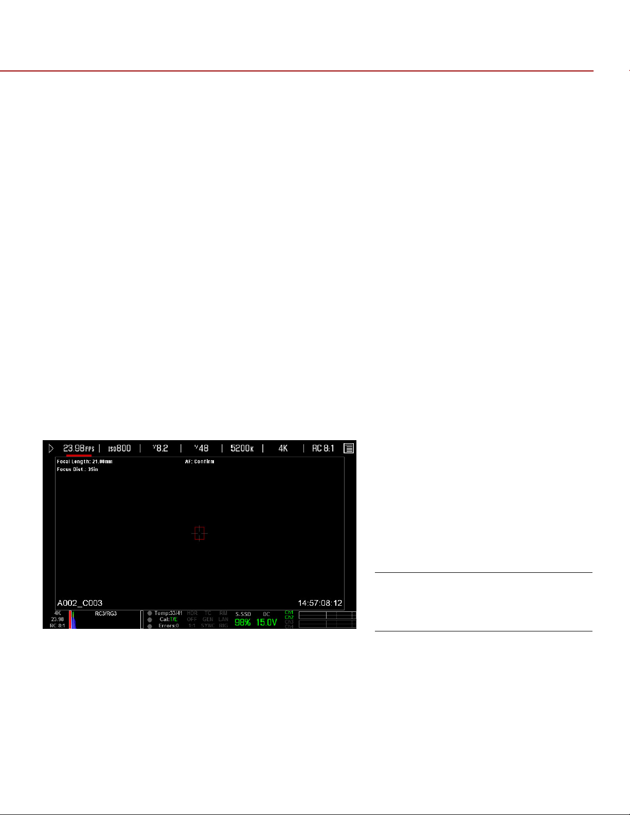
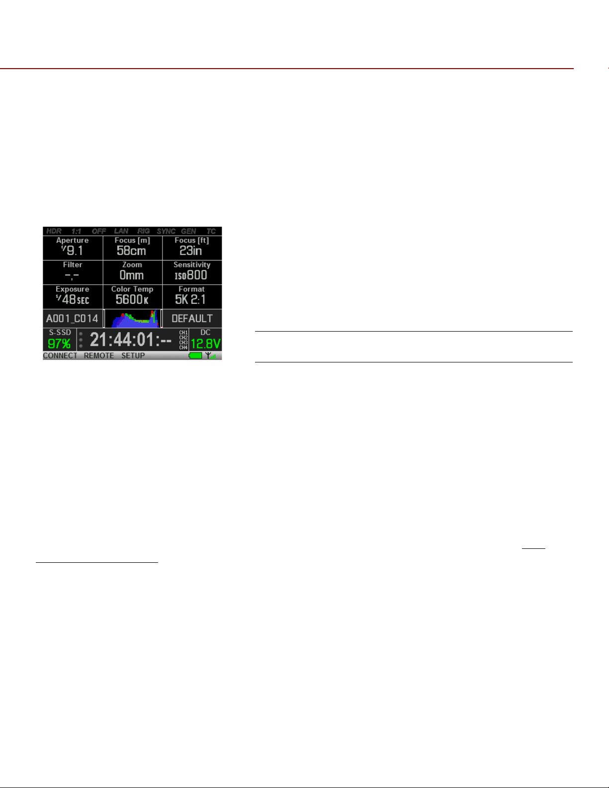
GRAPHICAL USER INTERFACE AND NAVIGATION
RED LCD/TOUCHSCREEN LCD, BOMB EVF, EXTERNAL MONITORS
The following is a general description of the structure of the camera’s Graphical User Interface (GUI) which
overlays the video monitor signal on the Viewfinder output(s) of the camera.
CHANGE
PROJECT
FRAME RATE /
QUALITY
LEVEL BAR
METER
The display elements include:
Audio Meter:
Cal:T/E
Audio input selection and levels
: Indicator of relative change in sensor
temperature and exposure since your last
calibration
SOURCE / STATUS
near clip
Clip Meter:
Cursors:
RGB sensor RAW clipping status
Reference cursors – Safe Action / Safe
Title, Picture Center, Grid Overlay
Clip Level Bar:
COPYRIGHT © 2013 RED.COM, INC
Relative number of RAW pixels
Indicates if any frames were dropped during
Drop:
955-0002_v4.0, Rev-A | 45

RED EPIC OPERATION GUIDE
recording of the clip
Noise Level Bar:
Relative number of RAW pixels
F Stop:
are installed
False Color Mode:
mode
Frame Guide:
Frame Rate:
Genlock:
signal / HD-SDI sync to genlock
HDR Mode:
Histogram:
ISO Rating:
LAN:
connection
Lens Info:
Canon or Cooke lenses.
Magnify:
Media Status:
media capacity in %
Menu ICON :
touchscreen LCD - Opens the Secondary Menus
Next Clip Filename:
be shot next
Functional when optional mount and lens
Displays false color overlay
Record or Projection area
Current frame capture rate
Indicates presence of valid Genlock
Displays HDRx mode status
RGB Histogram.
Camera sensitivity
Indicates communication via Ethernet
Lens information when using specific
Tallies 1:1 if magnify is selected
Media location and remaining
In the upper Right corner on the
Filename of the clip that will
in noise
Playback ICON :
touchscreen LCD - Accesses the Playback
Function
Power:
remaining battery capacity Including current
supply voltage
Project Frame Rate:
Quality:
Resolution
RIG:
RM:
Shutter Speed:
Shutter Sync:
status
TC:
signal and Jam Sync status
Temperature:
temperature in that order (xx/xxC)
Timecode:
White Balance:
Indicates D.C supply voltage or % of
REDCODE setting
Record Resolution
Indicates 3D rig metadata is present
Indicates communication to REDMOTE
Indicates presence of valid SMPTE timecode
Current timecode value
In the upper Left corner on the
Current project TIME BASE
Exposure Time (or Degrees)
Indicates sensor shutter sync
Displays camera sensor and core
Color Temperature
The GUI is broken down into the following three main sections: the Upper Status Row, the Live Action Area,
and the Lower Status Row. On VIEWFINDER output(s), all three sections are visible, on PREVIEW outputs
only the Live Action Area and associated graphic overlays are visible. On PROGRAM outputs, none of the
graphic overlays are visible, i.e. a PROGRAM output is defined to be a CLEAN FEED output.
UPPER STATUS ROW
Provides immediate feedback on the most critical image composition parameter settings, including (from
Left to Right):
Playback Access (Touchscreen)
Current frame capture rate
ISO Rating
COPYRIGHT © 2013 RED.COM, INC
Shutter Speed (or Shutter Angle)
White Balance
Record Resolution
955-0002_v4.0, Rev-A | 46

RED EPIC OPERATION GUIDE
Record Quality Secondary Menus Access (Touchscreen)
Whichever parameter is underlined with a red bar may be immediately adjusted by pressing ENTER in the
Navigation Group of the Side Handle or REDMOTE, then using the Scroll Wheel to change the value of that
parameter. To confirm the parameter change press ENTER a second time.
NOTE: Shutter angle is displayed in Absolute mode by default, as indicated by Yellow text.
If the red bar is not on the parameter you wish to change, first use the Scroll Wheel to position the red bar
under that parameter, then press ENTER, adjust with the Scroll Wheel and press ENTER a second time to
confirm the value change.
In the above GUI example, the Scroll Wheel has been used to move the red cursor to the Shutter Speed
parameter; and the ENTER key has been pressed. This reveals the Parameter Adjust Widow. Adjust the value
using the Scroll Wheel and then press ENTER to confirm the value change, then close the sub-menu.
LIVE ACTION AREA
Contains the recorded image area plus Surround View™ look around area, plus overlays for Frame Guide,
Safe Action / Safe Title and the current Clip Name and Timecode values. Each overlay may be color coded in
one of 5 colors to maximize the contrast between the guide(s) and scene being captured.
COPYRIGHT © 2013 RED.COM, INC
955-0002_v4.0, Rev-A | 47

RED EPIC OPERATION GUIDE
LOWER STATUS ROW
The Lower Status Row provides feedback on key systems level camera values, including:
Clip Settings
Exposure (Histogram)
Temperature, Power & Sync
Media Status
Power Status
Audio Levels
COPYRIGHT © 2013 RED.COM, INC
955-0002_v4.0, Rev-A | 48

RED EPIC OPERATION GUIDE
ICON Behavior
CAL:T/E
T or E Green - No change in sensor temperature or exposure from the levels recorded during calibration
T or E Yellow - Slight change in sensor temperature or exposure from the levels recorded during calibration
T or E Red - Significant change in sensor temperature or exposure from the levels recorded during
calibration
The - and + indicate whether the sensor temperature or exposure has decreased or increased
NOTE: The T and E change colors independently of each other.
TC
TC Gray - No analog time code is currently detected
TC Red - Analog time code is being detected, but the use of it is not enabled
TC Green - Analog time code is being used to jam the time of day time code. TC will revert to gray if the
signal is no longer detected
GEN
GEN Gray - No genlock signal is currently detected, or the presented signal cannot crosslock to project
(24.00 fps vs. 23.98 fps)
GEN Red - During process of sync, or if genlock is lost while recording
GEN Green - A genlock signal matching the current HD-SDI monitor rate has been locked to it
GEN Yellow - When timing is cross-locking to compatible but not matching monitor rate. i.e. genlock =
24.00, HD-SDI monitor rate = 25.00
NOTE: 3D operation should not be done if GEN is yellow. This is a warning that genlock source settings and
camera settings are not aligned. Phasing of the sync between cameras cannot be guaranteed when GEN is
yellow.
SYNC
SYNC Gray - The sensor sync mode is not Genlock
SYNC Red - The sensor sync mode is Genlock, but it is not locked to any genlock signal, or genlock or
sensor sync is lost while recording
SYNC Green - A genlock signal compatible with the HD-SDI monitor rate has been locked to and the sensor
timing is also locked to it
POWER STATUS
If powering camera through DC power, the current voltage will be displayed. If using batteries, the remaining
battery time displays.
If using a REDBRICK or similar external battery to power the camera through DC IN, power status displays
COPYRIGHT © 2013 RED.COM, INC
955-0002_v4.0, Rev-A | 49

RED EPIC OPERATION GUIDE
the current supply voltage available from the battery. Supply voltage decreases as battery is discharged, the
displayed text is color coded as follows:
Green = 12.0 V and up Yellow = 11.9 – 11.8 V Red = 11.7 – 11.6 V
NOTE: The camera will automatically power down if supply voltage drops to 11.5 Volts.
If using a REDVOLT battery in the Side Handle or Battery Module to power the camera, power status
displays the location of the power source (example: SH: Side Handle; RM: Rear Module) and reports the
remaining battery capacity and the displayed text is color coded as follows:
Green: >10 minutes Yellow: 5-10 minutes Red: <5 minutes
If using a RED BRICK battery connected to DC IN, power status displays BRICK and reports the % of
remaining battery capacity and the displayed text is color coded as follows:
Green: >10 minutes Yellow: 5-10 minutes Red: <5 minutes
RAW CLIP METER
The RAW Clip meter looks a traffic light style meter and indicates if either of the Red, Blue or
Green channels of the RAW sensor data are clipping. This meter is unaffected by White
Balance, ISO, VIEW or LOOK settings and therefore represents a true measurement of the
exposure levels of the sensor at all times.
RAW NOISE LEVEL BAR
The RAW noise bar displays the amount of pixels in the image that are in noise. For example, if the bar is
about 1/8 of the total height, this would indicate approximately 1/8 of the total pixels in the image are at an
exposure level at risk of displaying noise when pushed at higher ISO or FLUT values in post-production.
RAW CLIP LEVEL BAR
The RAW clip level bar displays the amount of pixels in the image that are clipping. For example, if the bar is
about 1/4 of the total height, this would indicate approximately 1/8 of the total pixels in the image are at an
exposure level at risk of clipping and may not be recoverable by lowering ISO or FLUT values in postproduction.
COPYRIGHT © 2013 RED.COM, INC
955-0002_v4.0, Rev-A | 50

RED EPIC OPERATION GUIDE
COPYRIGHT © 2013 RED.COM, INC
955-0002_v4.0, Rev-A | 51

RED EPIC OPERATION GUIDE
SIDE HANDLE
Side Handle LCD Display
As you navigate and adjust settings on the camera (main menu settings only), they will be reflected on the
Side Handle LCD display.
The display elements include:
Frame Rate:
ISO Rating:
Power:
Quality:
Image capture rate
Camera sensitivity
Camera power status (DC Shown)
REDCODE setting
REDMOTE
Resolution:
Shutter Speed:
White Balance:
Recording Resolution
Exposure Time (or Degrees)
Color Temp
REDMOTE Display
The display elements include:
Battery Indicator:
status (shown) of REDMOTE
Camera ID:
Clip Filename:
shot
Clip Meter:
False Color Mode:
COPYRIGHT © 2013 RED.COM, INC
Displays camera ID (DEFAULT shown)
RGB sensor RAW clipping status
Displays battery life or charge
Filename of the clip that will be
Displays false color overlay
mode
Frame Rate:
Genlock:
signal / HD-SDI sync to genlock
HDR Mode:
Histogram:
ISO Rating:
Current frame capture rate
Indicates presence of valid Genlock
Displays HDRx mode status
RGB Histogram
Camera sensitivity
955-0002_v4.0, Rev-A | 52

RED EPIC OPERATION GUIDE
Indicates communication via Ethernet
LAN:
Resolution
Recording Resolution
connection
Magnify:
Media Status:
media capacity in %
Power:
remaining battery capacity Including current
supply voltage
Project Frame Rate:
Quality:
Quality:
Resolution
Tallies 1:1 if magnify is selected
Media location and remaining
Indicates D.C supply voltage or % of
Current project TIME BASE
REDCODE setting
REDCODE setting
Record Resolution
Indicates 3D rig metadata is present
RIG:
Shutter Speed:
Shutter Sync:
status
Indicates presence of valid SMPTE timecode
TC:
signal
Timecode:
White Balance:
Wireless Status:
connected wirelessly
Exposure Time (or Degrees)
Indicates sensor shutter sync
Current timecode value
Color Temp
Displays signal strength when
NAVIGATING MENUS
The primary method to navigate Menus is via the Scroll Wheel on the REDMOTE or Side Handle. Press Enter
to open the menu, and then rotate the Scroll Wheel clockwise to move right, counter clockwise to move left.
However, the Left and Right direction Navigation Keys (REDMOTE or Side Handle) or Adjustment Ring (Side
Handle) may also be used for this purpose.
The Up Navigation Key selects the Advanced Settings menu when pressed (if parameter has an Advanced
Settings menu).
As an example, position the Cursor under the Shutter Speed (24FPS) icon and press the UP Direction Key to
access advanced adjustment values for Shutter Speed.
USING TOUCHSCREEN LCD
If operating a Touchscreen LCD, camera menu navigation may be made through finger gestures.
To adjust a parameter value, simply touch it, and then swipe the finger left / right to adjust its value.
To access an advanced parameter settings display, press and hold down on the parameter icon.
Touch anywhere outside the overlay windows to enter the value changes and to hide the sub-menus.
To enter the Secondary Menus, touch the MENU icon .
COPYRIGHT © 2013 RED.COM, INC
955-0002_v4.0, Rev-A | 53

RED EPIC OPERATION GUIDE
To return to the Main Menus, touch the MENU icon again.
To access the Playback function, touch the arrow.
To exit the Playback function, touch the circle.
COPYRIGHT © 2013 RED.COM, INC
955-0002_v4.0, Rev-A | 54

RED EPIC OPERATION GUIDE
TOUCHSCREEN SHORTCUTS
The bottom portion of the touchscreen contains shortcuts to the most-used camera screens.
COPYRIGHT © 2013 RED.COM, INC
955-0002_v4.0, Rev-A | 55

RED EPIC OPERATION GUIDE
ACCESSING SOFT KEYS
User-programmable Soft Keys A-D and 1-4 may be accessed by tapping the left or right regions of the
touchscreen. Programming soft keys is explained later in the manual.
Soft Key without Labels
Soft Key with Labels
COPYRIGHT © 2013 RED.COM, INC
955-0002_v4.0, Rev-A | 56

RED EPIC OPERATION GUIDE
POWER DOWN
NOTE: Camera will automatically power down if supply voltage drops to 11.5 Volts.
POWER MENU
1. Select the MENU icon in the right corner of the Upper Status Bar to reveal the Secondary Menus.
2. Select POWER.
3. Select SHUTDOWN.
4. The camera will immediately power down.
COPYRIGHT © 2013 RED.COM, INC
955-0002_v4.0, Rev-A | 57

RED EPIC OPERATION GUIDE
LOCK / UNLOCK TOUCHSCREEN OPRERATION
LOCK
To lock out the touchscreen operation, touch and hold the MENU icon until the LOCK icon displays;
indicating the touchscreen has been locked out. When locked, the main menu will be displayed.
UNLOCK
To unlock out the touchscreen and allow normal operation, touch and hold the LOCK icon until the
MENU icon displays; indicating the touchscreen has been unlocked.
COPYRIGHT © 2013 RED.COM, INC
955-0002_v4.0, Rev-A | 58

RED EPIC OPERATION GUIDE
A
B C
FIRST TIME USE – SETTING UP YOUR RED EPIC
ATTACH POWER SOURCE
If a REDVOLT battery is installed in the Side Handle and DC power is connect through the DC IN connector,
the DC IN power supply has priority and will power the camera instead of the battery.
BATTERY
Connect a RED battery to the camera in one of the following ways:
SIDE HANDLE
Attach a Side Handle and insert a REDVOLT battery.
INSTALL
Press Battery Door Release Button (A)
Open Battery Door (B)
Press Upwards on Retainer (C)
Insert a REDVOLT Battery Until it is Fully Seated
and Retainer (C) Clicks into Place
1. Press the battery door release button (A).
2. Open battery door (B).
3. Press upwards on retainer (C).
4. Insert a REDVOLT battery until it is fully seated and retainer (C) clicks into place.
5. Close battery door.
COPYRIGHT © 2013 RED.COM, INC
955-0002_v4.0, Rev-A | 59

RED EPIC OPERATION GUIDE
A B
R EMOVE
1. Press the battery door release button (A).
2. Open battery door (B).
3. Press upwards on retainer (C) to release battery.
4. Remove battery from side handle.
QUAD BATTERY MODULE
Attach a Quad Battery Module and insert one or more REDVOLT batteries.
INSTALL
Insert battery into desired location and press until a click is heard and battery is seated.
REMOVE
Remove
Battery
1. Press the battery eject button (A) for desired battery.
2. When battery pops out, remove battery from battery module (B).
RED BRICK
Attach to the camera using a V-Plate and 2B-to-1B Power Adapter Cable P/N 790-0138 to the DC IN
connector.
DC POWER
Connect a DC power source to the camera in one of the following ways:
Plug the RED AC Power Adapter into AC power, and the LEMO connector to the DC IN connector.
COPYRIGHT © 2013 RED.COM, INC
955-0002_v4.0, Rev-A | 60

RED EPIC OPERATION GUIDE
Plug the RED CHARGER into AC power, and the LEMO connector to the DC IN connector via 2B-to-1B
Power Adapter Cable P/N 790-0138.
Plug a 12V XLR based power source into the DC IN connector via adaptor cable P/N 790-0164.
NOTE: The maximum sustainable power load of the DSMC AC Power Adapter is 150W (15V@10A). The
output of the adapter is over current protected, and will shut down if an excess load condition occurs. If the
output trips for any reason, remove any external loads from the camera, such as lights, motors etc, turn off
the Adapter and repeat the above procedure.
POWER UP
Locate the camera’s Power ON / OFF button on the right face of the Brain. If the Power Status LED is
illuminated Red, depress and then release the Power / Record button. If not illuminated, check your battery
charge status or external power source cable connection. Once powered up the Power Status LED will
illuminate Green, confirming the camera is ready to use.
PREPARING TO RECORD
Before each days recording, the camera should be prepared as follows:
Physically set-up camera as desired.
Verify camera is using the latest firmware version at
camera firmware. Refer to
Insert a blank (or previously used but erasable) REDMAG 1.8” SSD and format it.
Perform a BLACK SHADING CALIBRATION of the Sensor.
Check your PROJECT SETTINGS (Time Base, Record Resolution, Record Quality, etc.).
Frame, focus and record.
APPENDIX A: UPGRADING CAMERA FIRMWARE.
www.RED.com/support
and if appropriate, upgrade the
CONNECT AND FORMAT MEDIA
Identify a REDMAG 1.8” 64GB, 128GB or 256GB SSD that has not previously been recorded to, or is not a
camera master and may therefore be erased and re-used. Aligned the RED logo of the SSD to the outside,
and then push the SSD firmly, but without excessive force, into the slot in the Side SSD Module.
NOTE: When fully inserted, the SSD media protrudes slightly from the SSD slot.
When SSD media is inserted into the camera, the camera will recognize if the media is unformatted:
On LCD, EVF and external monitors, in the media section of the GUI, NONE will be displayed twice (as
opposed to when no media is inserted, the GUI displays NONE with three dashes below “---“).
On REDMOTE, NONE will be displayed twice (as opposed to when no media is inserted, the GUI displays
NONE with three dashes below “---“).
On the Side Handle, NA will be displayed (same as if no media is present).
To format the media select SECONDARY MENUS > MEDIA > FORMAT MEDIA.
COPYRIGHT © 2013 RED.COM, INC
955-0002_v4.0, Rev-A | 61

RED EPIC OPERATION GUIDE
When FORMAT is selected, a FORMAT dialog box will appear allowing you to add Camera Identity and 3D
Position properties when formatting. When desired options are set, select FORMAT.
NOTE: If any clips will be erased on the attached media, you will be informed of the number.
PERFORM A BLACK SHADING CALIBRATION
Refer to SECONDARY MENUS > SETTINGS > MAINTENANCE > CALIBRATION for complete details for
performing a Black Shading Calibration.
ADJUST PROJECT SETTINGS
TIME BASE
The project TIME BASE defines the rate at which the footage will be played back. When changing the
project frame-rate, the sensor frame-rate will default to the project rate, but may be over-ridden using the
sensor frame-rate controls.
Multiple projects with differing time bases may be stored on a media cartridge (SSD).
To adjust the project TIME BASE, press the MENU button on the Side Handle or REDMOTE. Then use the
Scroll Wheel or Direction Keys to navigate to SETTINGS > PROJECT > TIME BASE and press ENTER. Adjust
to the desired value using the Scroll Wheel and press ENTER once more to confirm.
COPYRIGHT © 2013 RED.COM, INC
955-0002_v4.0, Rev-A | 62

RED EPIC OPERATION GUIDE
If using a Touch Screen, select SECONDARY MENUS > SETTINGS > PROJECT > TIME BASE. Adjust by
sliding your finger up / down or tapping on the desired value, and then press anywhere else on the touch
screen to confirm.
The following TIME BASES are currently available:
23.98 fps
24.00 fps
25.00 fps
29.97 fps
47.96 fps
48.00 fps
50.00 fps
59.94 fps
RECORD RESOLUTION
To adjust Record Resolution, navigate the Cursor to the RESOLUTION icon in the Upper Status Row and
press the Navigation Group ENTER key. Adjust to the desired value using the Scroll Wheel and press ENTER
a second time to confirm.
If using a Touch Screen, press the RESOLUTION ICON, adjust RESOLUTION by sliding your finger left /
right, or tap on the desired resolution, and then press anywhere else on the touch screen to confirm.
The following Recording Resolutions are currently available:
5K
5K HD
5K 2:1
5K ANA
4K
4K HD
3K HD
2K
2K HD
1K HD
1K WS
5K WS
3K
2K WS
RECORD QUALITY (REDCODE)
Allows adjustment of REDCODE settings.
Range is 3:1 to 18:1
Default is 8:1
Use the scroll ribbon to select a target REDCODE compression ratio.
COPYRIGHT © 2013 RED.COM, INC
955-0002_v4.0, Rev-A | 63

RED EPIC OPERATION GUIDE
The camera will automatically select the closest REDCODE to the desired target.
The display will always show the "current" compression ratio being used by the camera.
If the camera is able to achieve the desired target compression ratio, it will be displayed in white. If the
camera is unable to achieve the target compression ratio, it will be displayed in yellow.
The current compression ratio will automatically be re-calculated when changes are made to Resolution,
FPS, HDRX Mode, Media, or Target REDCODE.
CAMERA ID (SLATE)
If operating on a multi-camera production, enter a different Camera ID for each camera; otherwise skip this
step; the camera is ready to shoot.
The Camera ID is set when the media is formatted. Refer to ADVANCED MENU > MEDIA for details.
RECORDING
Ensure a formatted REDMAG 1.8” SSD is inserted in the camera’s Side SSD Module, then fully depress any
one of the RECORD buttons located on the Brain, Side SSD Module, Side Handle or REDMOTE.
Fully depress again to stop recording. The camera will automatically create a unique and sequential file
name for each clip recorded on the SSD based on the Camera’s I.D set in the MEDIA menu.
REDCODE RAW data recordings store the Color Temperature and Exposure (ISO) and any RGB color
processing values you use in the monitor path as metadata. This metadata is used in REDCINE-X or other
post-production software as initial white balance, exposure and color correction points however, you are
free to change these values at any time when you process the RAW footage.
Time Code and Edge Code values used by the camera are Non Drop Frame (NDF); Drop Frame (DF) is not
supported. Audio is captured uncompressed at 24-bit resolution, 48KHz sample rate per channel.
Digital media such as REDMAG 1.8” SSDs are very robust, but should be treated with equal care as exposed
film or a videotape master. We recommend storing digital media that contains your footage in a secure
location and backing up the data to a digital archival media, such as data tape or hard disk drive.
COPYRIGHT © 2013 RED.COM, INC
955-0002_v4.0, Rev-A | 64

RED EPIC OPERATION GUIDE
RECORD INDICATOR
When recording, the RED DSMC camera provides a variety of record indications (tallies):
Timecode, normally displayed in white colored text, will be displayed in red colored text.
A small Red dot will appear in the top right corner of the VIEWFINDER output(s).
The REC LED on the right side of the camera Brain will illuminate Red.
REDMOTE upper LED will illuminate Red, and the Timecode will turn Red.
If using a BOMB-EVF, the LED on the front will illuminate Red if Tally is enabled
SMPTE-RP188 timecode VITC-2 HANC metadata record flag will be enabled on HD-SDI outputs.
If enabled in the USER KEYS menu, the GPO trigger output in the CNTL connector will pulse.
COPYRIGHT © 2013 RED.COM, INC
955-0002_v4.0, Rev-A | 65

RED EPIC OPERATION GUIDE
PLAYBACK
Playback is available on the RED DSMC Camera by going to SECONDARY MENUS > SETTINGS >
PLAYBACK or by touching the Playback arrow icon in the upper Left corner of the GUI.
The Playback function will display.
For complete details, go to SECONDARY MENUS > SETTINGS > PLAYBACK.
COPYRIGHT © 2013 RED.COM, INC
955-0002_v4.0, Rev-A | 66

RED EPIC OPERATION GUIDE
MENU CONTROLS
Displayed in the Upper Display Group of the VIEWFINDER output(s), are FRAMERATE (FPS), EXPOSURE
(ISO), _._ (F/Stop), WHITE BALANCE, RESOLUTION, and QUALITY (REDCODE). These parameters are
adjustable directly through this screen. When using the touchscreen, directly to the right of these
parameters is the MENU icon which when pressed will take you to the secondary camera set up menus.
ADJUSTMENTS
BASIC SETTING ADJUSTMENTS
SIDE HANDLE / REDMOTE
The MENU button can be used to ENTER the secondary menus, as well as CANCEL inside lists and for
navigating back up menus.
Navigate to the desired setting using the NAVIGATION GROUP direction keys and press ENTER.
Use the Scroll Wheel or Adjustment Ring to increase or decrease the parameter value.
When the desired value has been selected, press ENTER to set.
BASIC ADJUSTMENTS USING SIDE HANDLE ONLY
Although not recommended, the Side Handle can be used stand alone to make basic adjustments to FPS,
ISO, Shutter Speed, Resolution and REDCODE located on the Main Menu screen. Use the Navigation Group
to make these adjustments while watching the cursor placement under the desired setting on the side handle
LCD. When desired setting is selected, press the Enter button to access, then use the Scroll Wheel,
Directional Pad or Adjustment Ring to make changes. When done, press the Enter button again to set the
changed parameter. The MENU button can be used to ENTER the secondary menus, as well as CANCEL
inside lists and for navigating back up menus.
TOUCHSCREEN
The MENU ICON can be used to ENTER the secondary menus, as well as CANCEL inside lists and for
navigating back up menus.
Touch the desired parameter for adjustment.
Slide your finger across the screen to scroll through the available parameter values.
When desired the parameter value has been selected, touch anywhere in the screen area to set.
To close an alpha numeric keypad when entering information directly, tap anywhere on the screen outside
the keypad.
COPYRIGHT © 2013 RED.COM, INC
955-0002_v4.0, Rev-A | 67

RED EPIC OPERATION GUIDE
ADVANCED SETTING MENUS
At this time, only FRAMERATE, F-STOP, SHUTTER SPEED and WHITE BALANCE on the MAIN MENU have
advanced settings.
SIDE HANDLE / REDMOTE
1. Navigate to the desired setting using the NAVIGATION GROUP direction keys and then press the UP
directional key.
2. Use the direction keys to navigate to the desired parameter adjustment field and press ENTER to
confirm.
3. Use the Scroll Wheel to adjust the selected parameter value.
4. When desired selection is made, press the MENU button to set.
TOUCHSCREEN
1. Press and hold the desired parameter to gain access to advanced setting adjustments.
2. Press the field - a keypad type menu may appear to allow adjustments.
3. Press the desired parameter settings to adjust.
4. When desired selection is made, press anywhere in the screen area to set and exit the advanced settings
submenu.
COPYRIGHT © 2013 RED.COM, INC
955-0002_v4.0, Rev-A | 68

RED EPIC OPERATION GUIDE
FRAME RATE (FPS)
FRAME RATE (FPS)
MIN
MAX
MIN
MAX
1
5K HD
1
96
3K HD
1
160
5K 2:1
1
101
2K
1
240
5K WS
1
121
2K HD
1
240
5K ANA
1
96
2K WS
1
303
4K
1
121
1K HD
1
359
4K HD
1
121
1K WS
1
400
MAIN MENU
Available options under the MAIN MENU are FRAMERATE (FPS), ISO (SENSITIVITY), F STOP, 1/SEC
(EXPOSURE), WHITE BALANCE, RESOLUTION, and QUALITY (REDCODE).
FPS
FPS is used to select an image capture frame rate that differs from the Project’s TIME BASE frame rate.
Ranges are as follows:
FORMAT
5K
96
FORMAT
3K
1 160
Default is 24 fps (or the selected Project TIME BASE frame rate if not 23.98 or 24.00 fps).
VARISPEED
When a frame rate other than the current TIME BASE has been selected, the FPS text will turn Yellow and
VARISPEED will be shown where the Audio Meter is normally displayed at the lower right of the display.
NOTE: Audio is not recorded in VARISPEED mode.
COPYRIGHT © 2013 RED.COM, INC
955-0002_v4.0, Rev-A | 69

RED EPIC OPERATION GUIDE
BASIC SETTINGS
Provides quick selection of the most common frame rates.
ADVANCED SETTINGS
When selected a numerical keypad will appear allowing the desired VARISPEED Framerate to be entered in 1
fps increments. Maximum frame rate is a function of RECORD RESOLUTION and REDCODE settings.
Granularity is 0.001 FPS.
A keypad is available for direct numeric entry of the VARISPEED FPS value. Touch the value bounded by the
+ and – labels to bring up, press outside the keypad to confirm the value.
COPYRIGHT © 2013 RED.COM, INC
955-0002_v4.0, Rev-A | 70

RED EPIC OPERATION GUIDE
ISO (SENSITIVITY)
Adjusts the camera’s ISO rating. The sensitivity value is adjustable in 1/3rd stop increments. When the ISO
rating is adjusted, the camera logs the change as metadata and the monitor path reacts accordingly. Higher
ISO values lead to brighter images in the monitor path, and vice versa.
Range is ISO 250 – 12800
Default is ISO 800
F STOP
Aperture controls the depth of field of the subject imaged by the camera, and in combination with the shutter
speed / angle setting controls the amount of light falling on the sensor. i.e. exposure. Increasing the F stop
to a higher number reduces exposure as well as increases the depth of field, decreasing the F stop to a
lower number increases the exposure and decreases the depth of field. You can chose either 1/3 or 1/4
stops.
RED DSMC Ti PL Mount Installed
When a lens equipped with Cooke’s S4/i system is attached to the DSMC Ti PL Mount, the camera will
display the current aperture (F stop) of the attached lens.
DSMC Canon Mount Installed
This menu will appear when a DSMC Canon Mount is installed and a Canon EF or EF-S Lens or equivalent is
attached (a Non-Canon EF or EF-S Lens may not function as smoothly or accurately). Adjusts the aperture (F
stop) of the attached lens.
The attached lens for the example shown is a Canon EF 24-70mm.
COPYRIGHT © 2013 RED.COM, INC
955-0002_v4.0, Rev-A | 71

RED EPIC OPERATION GUIDE
BASIC SETTINGS
Allows adjustment of the aperture (F stop) of the attached lens. The range will vary depending on the
attached lens.
ADVANCED SETTINGS
When selected, the advanced settings menu allows fine control over the f-stop value under APERTURE and
focal distance under FOCUS.
APERTURE (F STOP)
Provides the ability to enter the F stop value directly.
Range depends on attached lens.
Default depends on attached lens.
COPYRIGHT © 2013 RED.COM, INC
955-0002_v4.0, Rev-A | 72

RED EPIC OPERATION GUIDE
FOCUS
Provides the ability to enter the focal distance directly.
Range depends on attached lens.
Default depends on attached lens.
EXPOSURE
BASIC SETTINGS
Adjusts the exposure of each frame captured by the MYSTERIUM X sensor. Shutter speed presets are
provided for all common speeds (and shutter angles) for 24 / 25 fps and 50 / 60 fps project frame rates.
Decreasing Shutter Speed increases the amount of time over which light falls on the sensor, increasing
exposure and motion blur on any objects moving within the frame. Increasing Shutter Speed shortens the
amount of time over which light falls on the sensor, decreasing exposure and motion blur on objects moving
within the frame.
th
Range is 1/24
it is 1/24
Default is 1/48
If the camera is able to achieve the desired target exposure, it will be displayed in white. If the camera is
unable to achieve the target exposure, it will be displayed in yellow.
th
sec – 1/8000th sec - Slowest available speed is 1 second per frame / frame rate, so for 24 fps
sec.
th
Sec.
COPYRIGHT © 2013 RED.COM, INC
955-0002_v4.0, Rev-A | 73

RED EPIC OPERATION GUIDE
ADVANCED SETTINGS
When selected, the advanced settings menu allows fine control over the Exposure value, and permits entry
in any of the three following common units – EXPOSURE (Shutter Speed), INTEGRATION TIME or ABSOLUTE
ANGLE (Shutter Angle).
EXPOSURE (SPEED)
Provides the ability to enter the Exposure value as a Shutter Speed (1/xx sec).
Range is 2 – 1/8000
th
Sec - Slowest available speed is 1/frame rate, so for 24 fps it is 1/24th Sec.
Default is 1/48th Sec.
COPYRIGHT © 2013 RED.COM, INC
955-0002_v4.0, Rev-A | 74

RED EPIC OPERATION GUIDE
INTEGRATION TIME
Provides the ability to enter the Exposure value as a Shutter Integration Time (xx milliseconds).
Range is 0.125 to 41.708 mS (milliseconds)
Default is 20.833 MS
ABSOLUTE ANGLE
Provides the ability to enter the Exposure value as a Shutter Angle (xx Degrees).
Range is 1.000 to 360.000 Degrees
Default is 180.0 Degrees
As you adjust any of these three parameters, the camera will automatically calculate the equivalent value in
COPYRIGHT © 2013 RED.COM, INC
955-0002_v4.0, Rev-A | 75

RED EPIC OPERATION GUIDE
SHUTTER
DEGREES
SHUTTER
DEGREES
1/32
270
1/120
72
1/48
180
1/192
45
1/50
172.8
1/348
22.5
1/60
144
1/696
11
1/96
90
1/1000
8.6
DEGREES
SHUTTER
DEGREES
SHUTTER
270
1/32
72
1/120
180
1/48
45
1/192
172.8
1/50
22.5
1/348
144
1/60
11
1/696
90
1/96
8.6
1/1000
the other units, but as a quick reference here are some common Speeds and Angles.
Convert Shutter Speed to Absolute Angle (for 24 FPS)
Equivalent Degrees = (Shutter Speed x Frame Rate x 360)
E.g. = (1/48 x 24 x 360) = (8640/48) = 180
Convert Absolute Angles to Shutter Speed (for 24 FPS)
Equivalent Shutter = 1 / (Frame Rate x 360 / Angle)
E.g. = 1/ (24 x 360/180) = 1/ (8640/180) = 1/48
WHITE BALANCE
BASIC SETTINGS
Allows you to manually set Color Temperature in the range from 1,700 to 100,000 KELVIN.
Range is 1,700 K to 10,000 K.
Default is 5600K.
COPYRIGHT © 2013 RED.COM, INC
955-0002_v4.0, Rev-A | 76

RED EPIC OPERATION GUIDE
ADVANCED SETTINGS
When selected, allows additional adjustment of the White Balance. Available options are PRESET, COLOR
TEMP, TINT, and CALCULATE WHITE BALANCE. Press APPLY PRESET for settings to take effect.
PRESET
Available preset options are:
Shade
Cloudy
Daylight
Flash
: Preset to 9,000K
: Preset to 5,500K
: Preset to 7,500K
: Preset to 5,600K
Fluorescent
Tungsten
Incandescent
: Preset to 4,500K
: Preset to 3,200K
: Preset to 2,800K
COLOR TEMP
Allows you to manually set Color Temperature in the range from 1,700 to 100,000 KELVIN. Default is 5600K.
COPYRIGHT © 2013 RED.COM, INC
955-0002_v4.0, Rev-A | 77

RED EPIC OPERATION GUIDE
TINT
Color Temperature calculations assume a pure light source that may not be true in the specific scene the
camera is imaging. To compensate for any residual colorcast, the TINT parameter can adjust the RGB color
balance with a compensating Magenta - Green color component. Default is 0.000. When selected, a
secondary keypad will appear allowing you to enter the desired Tint value directly.
NOTE: Selecting Calc White Balance calculates a new Tint value. This is maintained if the Color Temp is
adjusted via the Color Temp parameter. If you select ANY presets, Tint will be reset to zero, which is the
default value.
CALC WHITE BALANCE
The Calc White Balance function analyzes the central 25% of the image visible in the monitor to calculate a
Color Temperature that will render a white object as white.
To use Calc White Balance function, place a White or Gray object under the ambient light, select the Calc
White Balance function and then press the Calc White Balance function box. Calc White Balance is also
assigned to a User Key on the REDMOTE and Side Handle as a factory default setting.
RESOLUTION
Allows adjustment of resolution.
Default is 5K 2:1
COPYRIGHT © 2013 RED.COM, INC
955-0002_v4.0, Rev-A | 78

RED EPIC OPERATION GUIDE
FRAME RATE (FPS)
RC
RC
RC
RC
RC
RC
RC
RC
RC
RC
5K
RC
RC
RC
RC
RC
RC
RC
RC
RC
RC
5K
RC
RC
RC
RC
RC
RC
RC
RC
RC
RC
RC
5K
RC
RC
RC
RC
RC
RC
RC
RC
RC
RC
RC
RC
5K
RC
RC
RC
RC
RC
RC
RC
RC
RC
RC
RC
RC
RC
RC
RC
RC
RC
RC
RC
RC
RC
RC
4K
RC
RC
RC
RC
RC
RC
RC
RC
RC
RC
RC
RC
RC
RC
RC
RC
RC
RC
RC
RC
RC
RC
RC
RC
RC
REDCODE
Allows adjustment of REDCODE settings.
Range is 3:1 to 18:1
Default is 8:1
Use the scroll ribbon to select a target REDCODE compression ratio.
The camera will automatically select the closest REDCODE to the desired target.
The display will always show the "current" compression ratio being used by the camera.
If the camera is able to achieve the desired target compression ratio, it will be displayed in white. If the
camera is unable to achieve the target compression ratio, it will be displayed in yellow.
The current compression ratio will automatically be re-calculated when changes are made to Resolution,
FPS, HDRX Mode, Media, or Target REDCODE.
REDCODE OPTIONS FOR VARIOUS FRAME RATES
Minimum frame rate is 1 sec per frame; maximum frame rate is a function of REDCODE setting, and record
resolution:
FORMAT
24
25
30
48
50
60
72
75
90
96
100
120
150
175
210
250
288
5K
HD
2:1
WS
ANA
-
-
-
-
-
3:1
4:1
4:1
6:1
7:1
8:1
3:1
3:1
4:1
6:1
3:1
3:1
4:1
6:1
3:1
3:1
3:1
3:1
3:1
5:1
3:1
5:1
6:1
8:1
6:1
8:1
5:1
6:1
5:1
6:1
9:1
9:1
9:1
8:1
7:1
10:1
9:1
9:1
8:1
7:1
12:1
11:1
11:1
9:1
8:1
12:1
-
-
-
12:1
-
-
-
-
-
12:1
12:1
10:1
9:1
12:1
10:1
-
-
-
-
-
-
-
-
-
-
-
-
-
-
-
-
-
-
-
-
-
-
-
-
300
4K
3:1
HD
3:1
3K
3:1
COPYRIGHT © 2013 RED.COM, INC
-
-
-
-
3:1
3:1
4:1
5:1
5:1
6:1
3:1
3:1
4:1
4:1
3:1
3:1
3:1
3:1
5:1
6:1
3:1
4:1
7:1
6:1
4:1
8:1
7:1
5:1
8:1
8:1
5:1
9:1
8:1
5:1
10:1
10:1
6:1
-
8:1
-
-
-
-
955-0002_v4.0, Rev-A | 79
-
-
-
-
-
-
-
-

RED EPIC OPERATION GUIDE
FRAME RATE (FPS)
3K
RC
RC
RC
RC
RC
RC
RC
RC
RC
RC
RC
RC
RC
RC
RC
RC
RC
RC
RC
RC
RC
RC
RC
RC
RC
RC
RC
RC
2K
RC
RC
RC
RC
RC
RC
RC
RC
RC
RC
RC
RC
RC
RC
RC
2K
RC
RC
RC
RC
RC
RC
RC
RC
RC
RC
RC
RC
RC
RC
RC
RC
RC
RC
1K
RC
RC
RC
RC
RC
RC
RC
RC
RC
RC
RC
RC
RC
RC
RC
RC
RC
RC
FORMAT
24
25
30
48
50
60
72
75
90
96
100
120
150
175
210
250
288
-
-
5:1
5:1
4:1
3:1
-
-
-
5:1
3:1
HD
2K
HD
WS
HD
3:1
3:1
3:1
3:1
3:1
3:1
4:1
3:1
3:1
3:1
3:1
3:1
3:1
3:1
3:1
3:1
3:1
3:1
3:1
3:1
3:1
3:1
3:1
3:1
3:1
3:1
3:1
3:1
3:1
3:1
3:1
3:1
3:1
3:1
3:1
4:1
3:1
3:1
3:1
3:1
4:1
3:1
3:1
3:1
3:1
5:1
5:1
6:1
3:1
3:1
3:1
3:1
3:1
3:1
3:1
3:1
3:1
3:1
3:1
3:1
7:1
4:1
3:1
3:1
3:1
4:1
4:1
3:1
3:1
SECONDARY MENUS
Press the Menu button on the REDMOTE / Side Handle or touch the MENU icon on the LCD to access
the Secondary Menus.
-
-
-
-
-
-
6:1
7:1
4:1
4:1
300
Available options in this menu screen are HDR, FOCUS, PRESETS, MEDIA, SETTINGS, and POWER.
EXPOSURE is not implemented at this time.
HDR MENU
Available options are HDR OFF, HDRx and STOPS.
NOTE: HDR mode cannot be modified when in Magnify 1:1 mode.
HDR ON / OFF
By default, HDRx is OFF (HDR button is illuminated Blue). In the Lower Status Group of the Viewfinder
screen, the HDR text is Gray, indicating HDRx is inactive.
To turn HDRx on, navigate to the HDRx button using the Navigation Group and press ENTER, or from the
touchscreen directly touch the HDRx button. In the Lower Status Group of the Viewfinder screen, the HDR
text will turn White, indicating HDRx is active.
COPYRIGHT © 2013 RED.COM, INC
955-0002_v4.0, Rev-A | 80

RED EPIC OPERATION GUIDE
STOPS
To adjust the STOPS parameter, select the Stops box and use the UP / DOWN arrows to adjust.
Range is 1 to 6.
Default is 2.
FOCUS MENU
The Focus Menu is used to enable and select Focus parameters including MODE, ZONES, and ENHANCED
A/F.
COPYRIGHT © 2013 RED.COM, INC
955-0002_v4.0, Rev-A | 81

RED EPIC OPERATION GUIDE
MODE
MANUAL FOCUS
You can select either MANUAL or CONFIRM. The default is MANUAL.
MANUAL
When selected, all focus operations are manual.
CONFIRM
Enables the Center or Spot focus target square. This mode provides additional focus assistance to the
photographer using RED, YELLOW, and GREEN color changes to the focus spot window. Inadequate subject
illumination and/or contrast may interfere with normal Focus Confirm operation.
For best results with Focus Confirm, operators should 'rock' the focus ring -- focusing through the point of
optimum focusing and back again in decreasing amplitude -- as when 'zeroing-in' for precision manual
focus.
AUTO FOCUS
NOTE: The following menus will ONLY appear if a DSMC Canon Mount is installed with a Canon or Sigma
lens attached.
With a DSMC Canon Mount installed and a supported lens attached, available options become MANUAL,
CONFIRM, SINGLE, CONTINUOUS, TOUCH TRACK, and RACK. Default is MANUAL.
All settings except MANUAL place a single target square on the screen (depending on the ZONES selection)
that indicates where the image is in focus.
Pressing the designated button for spot focus (REDMOTE / Side Handle button A default) will cycle you
through each Focus Mode option in order as you press the button repeatedly.
COPYRIGHT © 2013 RED.COM, INC
955-0002_v4.0, Rev-A | 82

RED EPIC OPERATION GUIDE
Performance of Auto Focus may be reduced under the following conditions:
The subject is dark or distant.
There is inadequate contrast between the subject and background.
The scene has reflective highlights.
The subject is backlit.
There is inadequate surface contrast/detail inside the window.
NOTE: Edge Mode can be used for additional assistance in these conditions. Refer to SETTINGS MENU >
DISPLAY > TOOLS > EDGE.
MANUAL
When selected, all focus operations are manual.
CONFIRM
Enables the Center or Spot focus target square. This mode provides additional focus assistance to the
photographer using RED, YELLOW, and GREEN color changes to the focus spot window. Inadequate subject
illumination and/or contrast may interfere with normal Focus Confirm operation.
For best results with Focus Confirm, operators should 'rock' the focus ring -- focusing through the point of
optimum focusing and back again in decreasing amplitude -- as when 'zeroing-in' for precision manual
focus.
SINGLE
A Focus / Record Button half-press performs single-shot AF. Optimized for rapid focus even under lowcontrast conditions. Works with both Center and Spot Zones.
CONTINUOUS
Once engaged with half-press, will attempt to keep objects in AF window in focus. Works best with good
lighting and contrast. Works with both Center and Spot Zones.
COPYRIGHT © 2013 RED.COM, INC
955-0002_v4.0, Rev-A | 83

RED EPIC OPERATION GUIDE
TOUCH TRACK
Dynamically updating positionable AF using touchscreen. Works with Spot Zone only. Keep AF Spot on
subject while moving across frame, will continuously focus on spot.
RACK
For quickly selecting two focus points and executing rack focus between them. Focus points are selected
using the Touchscreen. Shutter half-press executes rack movement. Works with Spot Zone only.
Rack mode remembers the last Center or Spot position and focus setting as the first rack point. A second
rack point needs to be defined by moving the spot window to the desired second location. If the spot
window is not moved, a shutter half-press will only cause the lens to execute a single AF adjustment on the
original Spot. On the other hand, when two rack points have already been defined, the rack point can be
updated by moving the spot to a new location. This will replace the rack point that is not in focus at that
moment.
ZONES
Available options are CENTER and SPOT. Default is CENTER. This control allows selection of the boxes
used to indicate objects in/out of focus.
COPYRIGHT © 2013 RED.COM, INC
955-0002_v4.0, Rev-A | 84
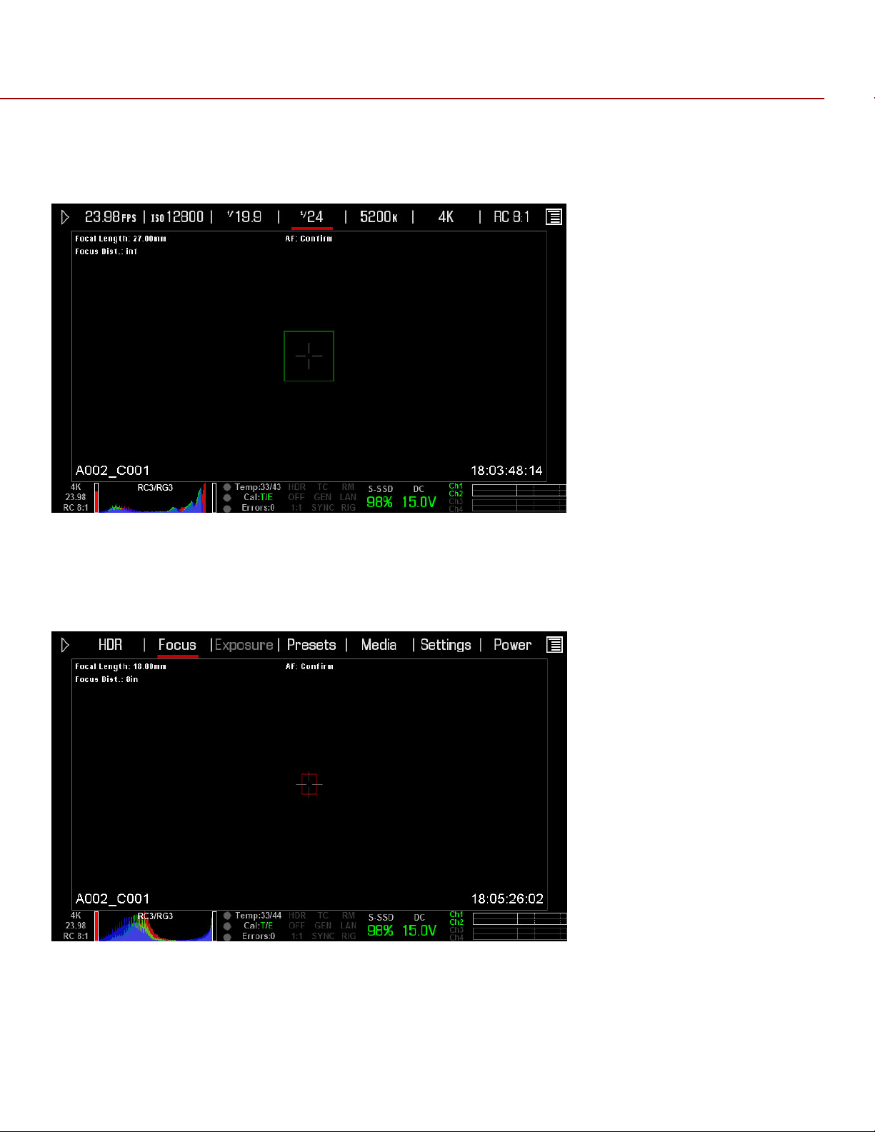
RED EPIC OPERATION GUIDE
CENTER
Provides a large target square for focus. When objects located in the target are in focus, the square is
Yellow or Green. When objects located in the square are out of focus, the square is Red.
SPOT
Provides a small target for precise focus (similar to Center focus, only smaller). When objects located in the
target are in focus, the target is Yellow or Green. When objects located in the target are out of focus, the
target is Red.
COPYRIGHT © 2013 RED.COM, INC
955-0002_v4.0, Rev-A | 85

RED EPIC OPERATION GUIDE
SPOT FOCUS INDICATOR
Moving
The spot focus square can be moved around the screen.
Touchscreen
Press and hold the Touchscreen on the location you wish to relocate the Spot Focus window. While pressing
on the touchscreen, you can drag and reposition the focus target.
Side Handle / REDMOTE
1. Navigate to the focus menu.
2. Press the down arrow on the Navigation Group.
3. The spot focus square line weight will increase and the Red cursor under FOCUS will dim slightly.
4. Use the directional arrows to move the Spot Focus square to the desired location.
COPYRIGHT © 2013 RED.COM, INC
955-0002_v4.0, Rev-A | 86
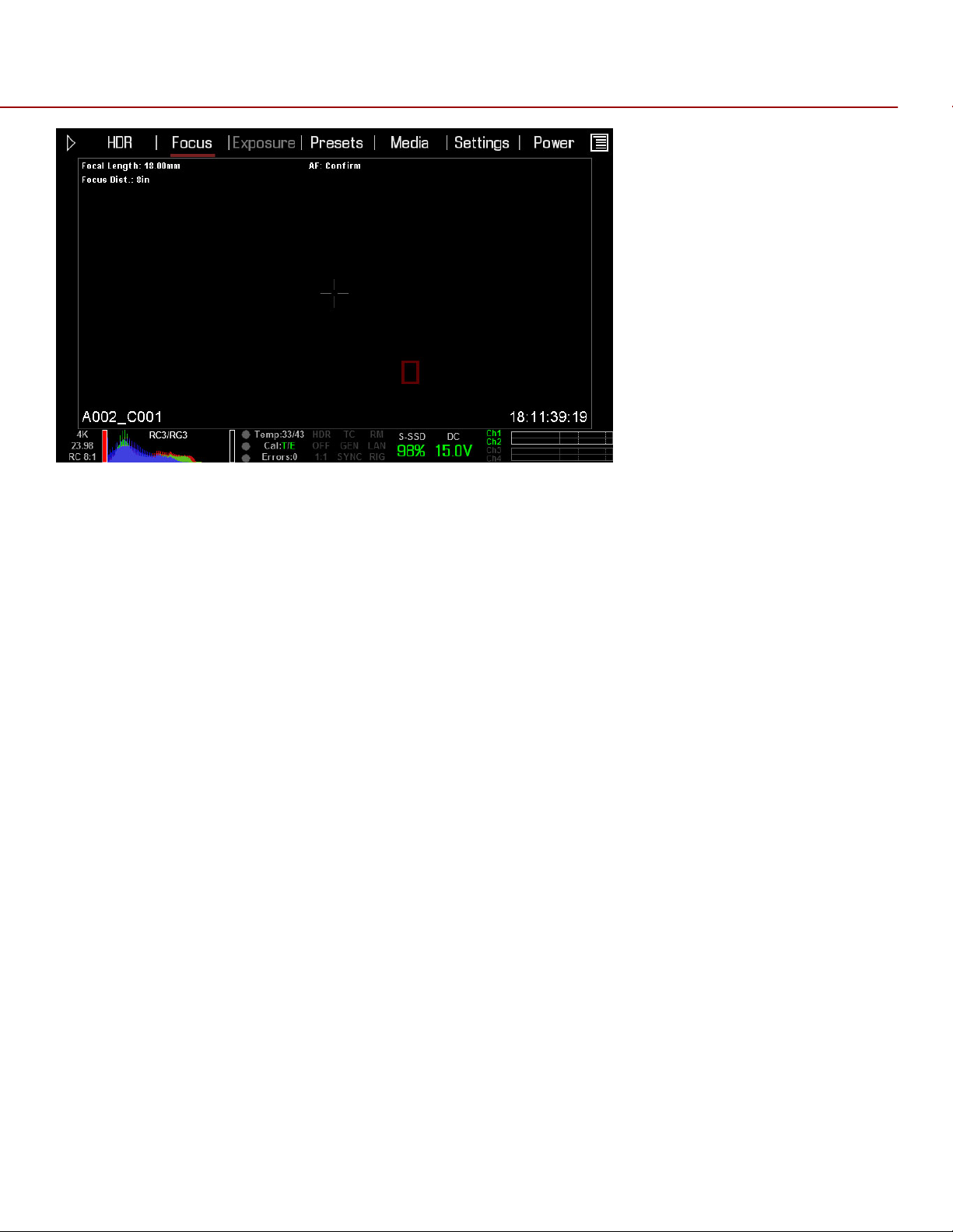
RED EPIC OPERATION GUIDE
5. Press the ENTER button.
6. To exit, Press the MENU button.
Resizing
The spot focus square can be resized using the Navigational Wheel or the Touchscreen.
Touchscreen
Each double-tap the Spot window will step through the three possible window sizes. After reaching the
largest size, the sequence will restart with the window at the smallest size.
Side Handle / REDMOTE
After following Steps 1-3 in the instructions for Spot window repositioning (see above), simply rotate the
Scroll Wheel to cycle through the three possible window sizes. Press MENU to exit.
ENHANCED A/F
Enhanced A/F has an auto-focus algorithm that offers better performance and improved visual indicators
when in Confirm mode. After you select the ENHANCED A/F checkbox, all monitors that are currently set to
Overlay or Menus mode will be dedicated to only using the Enhanced A/F feature. Each monitor using
Enhanced A/F will be in Clean mode (no overlay) with a set resolution of 720p and update frequency of 60
Hz. (You cannot select a frequency other than 60 Hz at this time.) You will no longer have control over these
monitors until you disable the Enhanced A/F feature.
COPYRIGHT © 2013 RED.COM, INC
955-0002_v4.0, Rev-A | 87
RED EPIC OPERATION GUIDE
CONFIRM INDICATORS
You can select any of the following CONFIRM INDICATORS when using Enhanced A/F: NONE, CIRCLE, BAR,
and PIE.
NOTE: You must be in Confirm mode in order to see the confirm indicators on the screen.
NONE
A square target displays, and operates just like the target square in Confirm mode
When objects located in the target are in focus, the target is Yellow or Green. When objects located in the
target are out of focus, the target is Red.
COPYRIGHT © 2013 RED.COM, INC
955-0002_v4.0, Rev-A | 88

RED EPIC OPERATION GUIDE
CIRCLE
A yellow circle displays around a square target. When objects located in the square target are in focus, the
target is Yellow or Green, and the yellow circle is almost the same size as the square. When objects located
in the target are out of focus, the square target is Red, and the yellow circle gets bigger.
BAR
A bar target displays. When objects located in the target are in focus, the target is Yellow or Green, and the
vertical bar on the right side is filled up. When objects located in the target are out of focus, the bar target is
Red and the vertical bar on the left side is almost empty.
PIE
A pie target displays. When objects located in the target are in focus, the pie target is Yellow or Green, and
COPYRIGHT © 2013 RED.COM, INC
955-0002_v4.0, Rev-A | 89
RED EPIC OPERATION GUIDE
the line around the curve is filled up. When objects located in the target are out of focus, the pie target is
Red and the line around the curve is almost empty.
COPYRIGHT © 2013 RED.COM, INC
955-0002_v4.0, Rev-A | 90

RED EPIC OPERATION GUIDE
LENS INFORMATION DISPLAY
RED DSMC TI PL MOUNT + LENS
When a RED DSMC Ti PL Mount is installed and a Lens equipped with Cooke’s S4/i system (or equivalent is
attached, the Focal Length and Focal Distance is displayed on the LCD, EVF and external monitors.
The focal length and focal distance values and range will vary depending on the attached lens. When the
focal length or focal distance of the lens is manipulated, the current values are displayed.
DSMC CANON MOUNT + LENS
When a DSMC Canon Mount is installed, and a Canon EF or EF-S Lens or equivalent is attached, the Focal
Length and Focal Distance is displayed on the LCD, EVF and external monitors. When AF is set to Manual or
Confirm mode, the focus distance displays as a pair of Near - Far distances. When it is in AF mode, a single
estimated Focus distance is displayed.
The focal length and focal distance values and range will vary depending on the attached lens. When the
focal length of the lens is manipulated, the current value is displayed under Focal Length. The Focal
Distance can be changed under MAIN MENU > -.- (F-STOP) > ADVANCED SETTINGS.
COPYRIGHT © 2013 RED.COM, INC
955-0002_v4.0, Rev-A | 91

RED EPIC OPERATION GUIDE
EXPOSURE MENU
Not implemented at this time.
PRESETS MENU
CAMERA PRESETS
Camera Presets are used to store and recall camera setup information such as LOOKs, key mappings, I/O
configuration, etc.
Your RED DSMC camera has a number of factory-installed presets.
APPLYING A PRESET
1. Select PRESETS from the secondary menus
2. Select the desired preset from the selection ribbon
3. Press APPLY button
4. Use the selection ribbon to select
Custom presets may be created to store groups of camera settings. For example; White Balance and ISO
settings for a particular shooting location can be captured as a preset and easily recalled later.
Presets can also be saved on an SSD and applied to other RED DSMC cameras.
CREATING A PRESET
1. Select PRESETS from the secondary menus
COPYRIGHT © 2013 RED.COM, INC
955-0002_v4.0, Rev-A | 92

RED EPIC OPERATION GUIDE
2. Select CREATE and enter a name for the new preset
3. Press OK on keyboard to save the preset name
4. Copy the desired settings from the left box of the interface to the right box using the select one (-->) or
All -> button
5. Select and press CREATE button (upper right corner of the screen)
COPYRIGHT © 2013 RED.COM, INC
955-0002_v4.0, Rev-A | 93

RED EPIC OPERATION GUIDE
6. The preset has been created and is now stored on the camera.
COPYRIGHT © 2013 RED.COM, INC
955-0002_v4.0, Rev-A | 94

RED EPIC OPERATION GUIDE
SHARING PRESETS
Presets may be shared between RED DSMC cameras using SSD media.
Camera to Camera
Camera to Multiple Cameras
Select PRESETS from the secondary menu:
Select Presets from Secondary Menu
COPYRIGHT © 2013 RED.COM, INC
955-0002_v4.0, Rev-A | 95

RED EPIC OPERATION GUIDE
COPY PRESETS FROM CAMERA TO SSD
Use scroll ribbon to select desired preset in camera box
Use --> button to add the preset to the SSD box
COPY PRESETS FROM SSD TO CAMERA
Use scroll ribbon to select desired preset in SSD box
Use <-- button to add the preset to the Camera box
The following window will appear
Select YES to copy the preset to the camera and apply the setting
Select No to copy the preset to the camera without applying the settings
LOOKS PRESETS
Look Presets allows you to save the specific color, image, white balance, and detail settings to be used for
other projects. As looks are created, they will be displayed alphabetically.
Looks Presets
COPYRIGHT © 2013 RED.COM, INC
955-0002_v4.0, Rev-A | 96

RED EPIC OPERATION GUIDE
For detailed information on LOOKs, see the REDCINE-X Operation Guide, available on RED.com
AUTO PRESETS
The Auto Presets function allows you to specify pre-selected presets on Startup and for Preview and
Playback
MEDIA MENU
The Media Menu is used to format media (SSD) prior to use on the camera as well as to Eject (unmount) the
media prior to removal from the camera. Available options when selected are SELECT MEDIA, FORMAT
MEDIA, EJECT MEDIA, and UTILITIES.
COPYRIGHT © 2013 RED.COM, INC
955-0002_v4.0, Rev-A | 97

RED EPIC OPERATION GUIDE
IMPORTANT: Media MUST be ejected from the camera before removal to prevent corruption and/or loss of
data on media.
SELECT MEDIA
Allows you to select the Media location to be used by the camera. Default is the Side SSD (S-SSD) Module.
FORMAT MEDIA
When selected, a new dialog box will appear allowing you to add properties to the media highlighted in the
Current Media box when formatting. Available options are REEL NO, CAM ID, CAM POS, and FORMAT to
format the media with the values entered.
NOTE: If clips are present on the media, you will be informed of how many clips will be erased when you
format the media.
REEL NO.
When selected a keypad will appear allowing you to enter a value between 1 and 999.
COPYRIGHT © 2013 RED.COM, INC
955-0002_v4.0, Rev-A | 98

RED EPIC OPERATION GUIDE
CAMERA ID (SLATE)
Identifies the camera with a letter A through Z. Default is A.
CAMERA POS (POSITION)
Identifies the camera position as Right, Left or Center. Default is Center.
EDGE TIMECODE START
Users may manually enter an Edge Timecode value (seldom used).
FORMAT
When selected, formats the media and adds the selected properties.
During formatting, the camera will display “Formatting” with a Green status bar. REDMOTE will also display
this message.
When formatting is complete, camera will display “The magazine was successfully re-formatted. The digital
magazine is ready for immediate use. REDMOTE will also display this message.
EJECT MEDIA
When selected will Eject (unmount) the media highlighted in the Select Media box.
When ejected, camera will display “Media Ejected Successfully”. REDMOTE will also display this message.
UTILITIES
Options are SECURE FORMAT.
SECURE FORMAT
Secure Format is a low-level format the rebuilds the SSD file system. It should only be used if the
performance of the SSD is in question.
COPYRIGHT © 2013 RED.COM, INC
955-0002_v4.0, Rev-A | 99

RED EPIC OPERATION GUIDE
NOTE: If clips are present on the media, you will be informed of how many clips will be erased when you
secure format the media.
COPYRIGHT © 2013 RED.COM, INC
955-0002_v4.0, Rev-A | 100
 Loading...