

INSTRU C T I O N M A N UAL
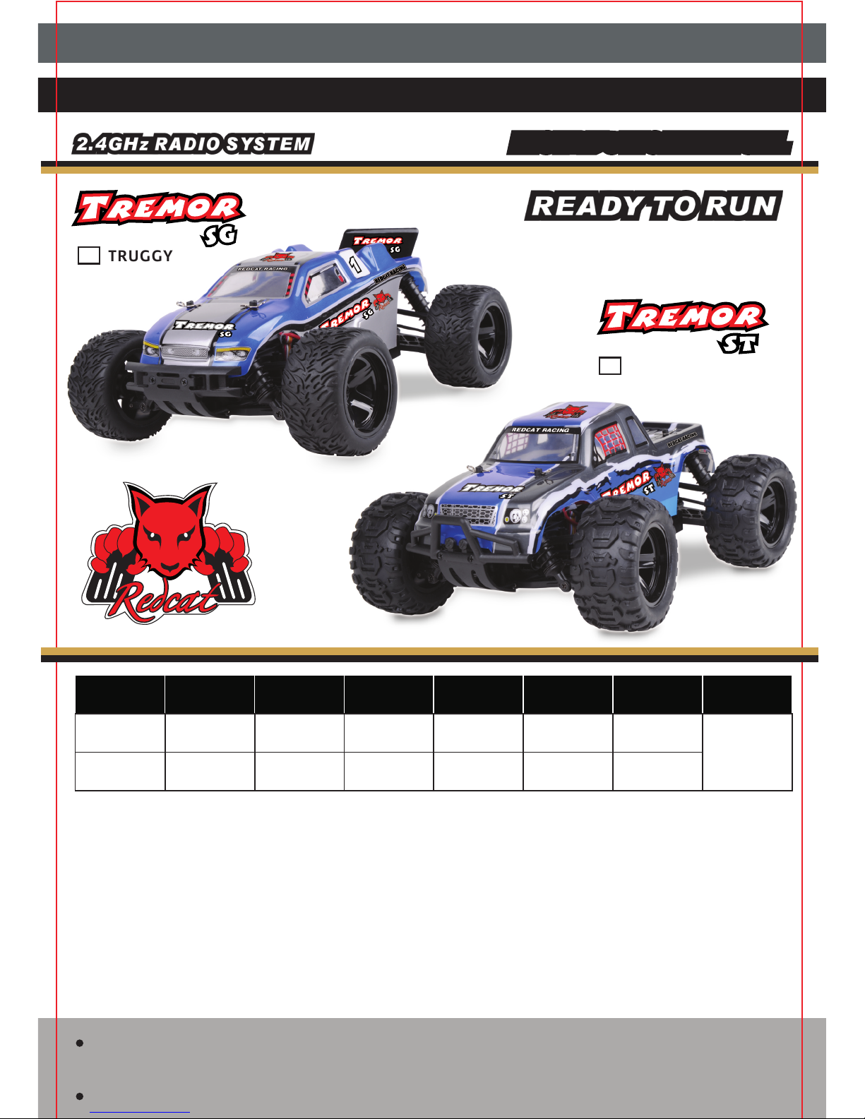
NAME LENGTH WIDTH HEIGHT
WHEELB AS E
WHEEL SIZE
GEAR RATIO
MOTOR &
BATTERY
TREMOR S T
RC 38 0 Motor,
Li-ion Battery
Pack (7.4V,
800mAH)
175mm
175mm
1: 11.44
1: 11.44
265mm 205mm 110mm
70mm(Dia.)
40mm(Width)
270mm 215mm 135mm
80mm(Dia.)
45mm(Width)
Notification: This data is subject to change without notice.
The Redcat Racing Tremor 1/16h Scale series are Ready to Run and include a Li-Ion 7.4V, 800mAH batter y
pack, charger.and charger adapter. Please use the included charger to charge your Li-Ion battery pack.
These vehicles feature a 3-in-1 unit (ESC/receiver/5 wire servo) and a 2.4GHz radio system, which are
considered entry-level hobby grade products and suitable for R/C beginners. Ball bearings and brass
bushings are installed throughout the vehicles.
Many optional parts are available to upgrade your vehicle. Please refer to the part lists or visit
www.redcatracing.com. If you perform a drive train upgrade, you must replace the entire system
(such as motor, ESC, receiver, ball bearings) so that all components are properly matched. Any malfunction
incurred by custom modification or incorrect operation of your vehicle will void your warranty.
This product is not a toy. It is not intended for persons under 14 years of age, unless closely
supervised by an adult.
This manual is subject to change without notice.
TRUGGY
MONSTER TRUCK
TREMOR S G
Please completely read and understand the entire manual before using, assembling and/or
disassembling your remote controlled car.
1/16TH SCALE 4WD ELECTRIC POWERED TRUGGY/MONSTER TRUCK

GENERAL INFORMATION
1
This user's manual contains the instructions you will need to assemble, operate and
maintain your vehicle. We know you are anxious to start driving, but it is very important
that you take time to read the manual even if you are an experienced R/C driver.
Carefully read and follow all instructions in the manual. Failure to follow the instructions
will be considered abuse and/or neglect and may void the warranty.
Your vehicle is designed to run on uneven or rough terrain. However, dust, sand, water and
carpet fibers can lodge in any moving parts and can damage your vehicle if not removed
promptly. Your warranty does not cover damage due to outside elements including sand,
dirt, water or any other debris. You are responsible for the maintenance and safe
operation of this vehicle.
This product is not a toy. It is not suitable for users under 14 years old unless supervised
by an adult.
Never attempt to re-assemble any electronic components. These have been carefully
calibrated at the factory.
Only use Redcat Racing manufactured parts to upgrade your car. If you perform a drive
train upgrade, replace the entire system (Such as motor, ESC/receiver unit and the like) so
that all components are properly matched. Any malfunction incurred by custom
modification will void your warranty.
Before driving your vehicle, please read this manual completely and examine your vehicle
for any defects. Test your remote control to make sure it functions properly and at the
range you plan to run your vehicle.
For best performance, some adjustments may be necessary.
This vehicle requires one battery pack, which is included with the car. The radio controller
requires three AA size batteries (not included). Make sure the vehicle's batteries have a
sufficient charge before driving or possible loss of control may result.
Always remove batteries from the vehicle and the radio controller when not in use.
Please operate your vehicle in an open area free of obstacles. Never operate your vehicle in
crowded street.
This product is fully assembled at factory. Redcat Racing is not responsible for damage
and/or accidents that occur as the result of custom modifications and/or incorrect
operation.
SAFETY INFORMATION
We want you to enjoy your R/C vehicle and to operate it with care. Failure to operate your
vehicle in a safe and responsible manner may result in injury to yourself and others and
may cause damage to proper ty.
2
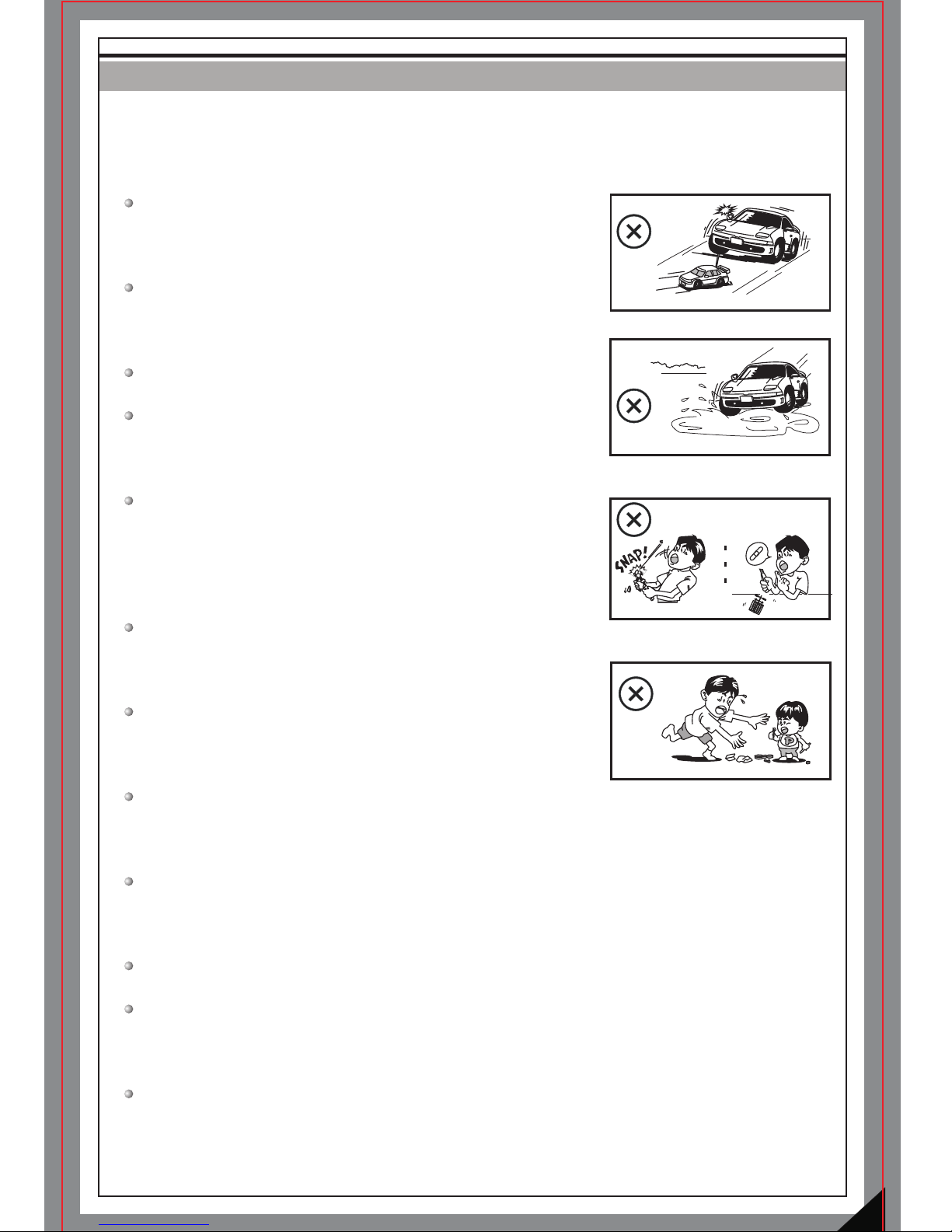
Read and understand all instructions carefully before use
and assembly/disassembly.
Do not run your vehicle on public roads or any area where
you may encounter pedestrian or vehicle traffic.
Do not operate in a congested area or in crowds.
Do not operate your vehicle with obstructed line of sight,
at night, or near water.
Your vehicle is radio controlled. Radio waves are subject to
interference. Radio interference can cause loss of control
of your vehicle.
Take care not to injure yourself while using tools to adjust
or upgrade your vehicle.
Since the model contains many small parts, keep out of
reach of children while assembling and/or disassembling.
When turning off your model, always turn off the receiver
(3-in-1 unit) first, before turning off the remote control.
Always remove the batteries from your vehicle and the
remote control when not in use.
If your vehicle becomes stuck, release the throttle, then retrieve it by hand.
Do not continue to apply the throttle or you may damage the motor and/or the
ESC/receiver unit.
Turn off your vehicle and discontinue use if it runs erratically. Do not run it again
until the issue has been found and resolved.
FAMILIARIZING YOURSELF WITH YOUR 2.4GHz RADIO SYSTEM
3
BATTERY INSTALLATION
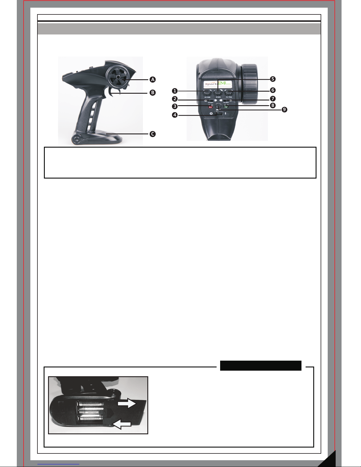
NOT ES :
A: Steering Wheel
B: Trigger
C: Battery Case
1: Steering Trim
2: Steering Reverse
3: Red Indicator
4: Power Switch
5: Steering Dual Rate
6: Throttle Trim
7: Throttle Reverse
8: Green Indicator
9: Bind(Pair) button
Your car is equipped with the new 2.4GHz radio system. Please read and understand all
instructions below before operating.
Steering Wheel: Proportionally operates the models right and left steering control.
Battery Case: Requires 3pcs of AA size batteries.
Power Switch: Used to turn the radio controller ON/OFF
Steering Dual Rate Dial: Allows you to change the amount of steering servo travel compared
to the amount of physical movement of the steering wheel.
Throttle /Steering Trims: Used to adjust the center trim of the throttle/steering channel.
Steering Reverse: Allows you to electronically switch the direction of steering servo travel .
For example, if you move the steering wheel to the right and the steering ser vo moves to the
left, flip the Steering Reverse Switch to make the steering servo move to the left.
Throttle Reverse : Allows you to electronically switch the direction that the motor operates
in relation to the throttle trigger. For example, if you pull the throttle trigger to accelerate
forward, but the model goes in reverse,
flip the Throttle Reverse Switch to make the model accelerate for ward.
Trigger: Controls the speed and braking ability of your car. Pull it to accelerate, release it to
decelerate, and push it to brake. Pushing it a second time activates the reverse feature.
Indicators: Shows battery power level. Green indicator flashing means battery power is low.
If both red and green indicators are flashing then the radio controller battery is too low to
control the model and you must replace with fresh batteries immediately.
Bind(Pair) button: It is used to bind your 2.4GHz radio system.
1) Slide the battery cover as shown and install 3pcs of
AA size batteries, positioning the polarity as indicated.
2) Replace the batter y cover after batteries are installed.
-Use batteries of same type.
-Remove batteries from the case if not in use.
-Always check the battery power.
-Dispose of exhausted batteries properly.
4
RUNNING YOUR CAR
1
TURN ON THE RADIO CONT ROLLE R
2
TURN ON THE RECEIVER O N YO UR CAR
CAUTION
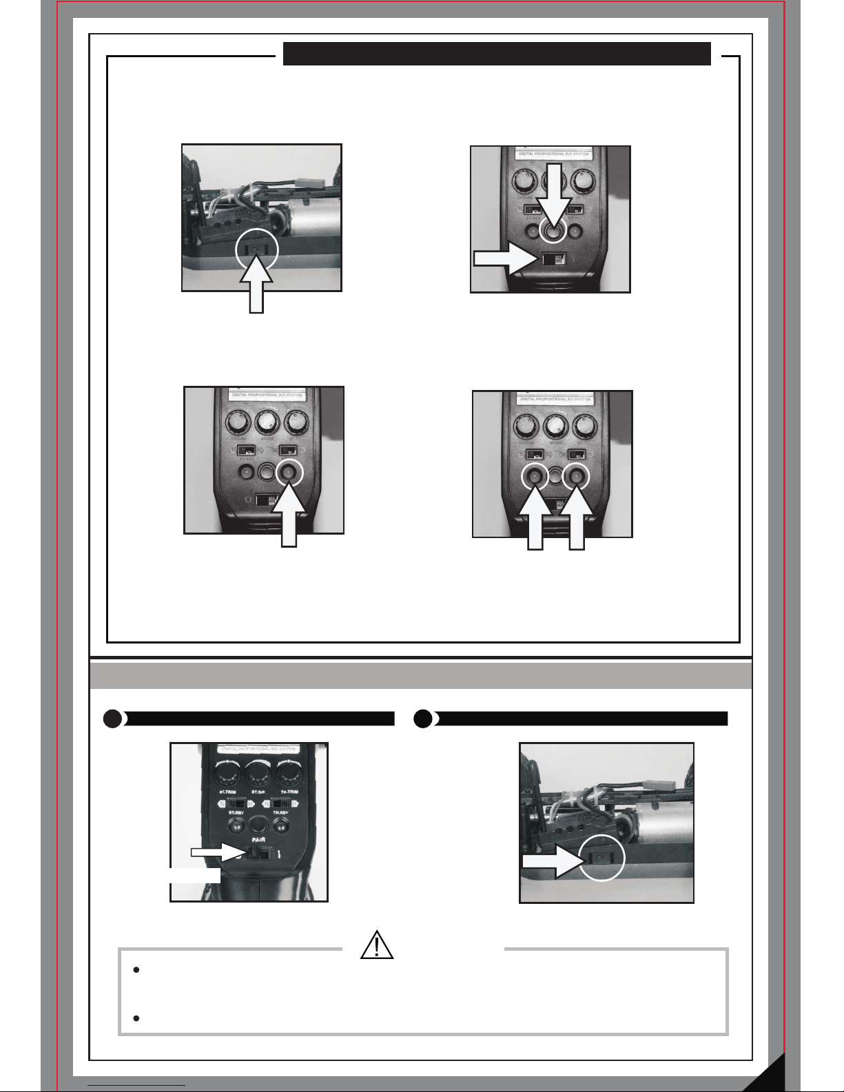
TO BIND THE RECEIVER TO THE RADIO CONTROLLER
Power Switch
Before running, make sure that the radio controller is bound with the receiver, which has been
done at factory. If the model is not responding to the controller, it is possible that the controller
and receiver are not bound, and you must perform the binding procedure following the
instructions below.
1)Turn on the receiver (3-in-1 unit) using the
power switch located on the side of the car.
(Note: Receiver and ESC are combined inside
the 3-in-1 unit.)
2) Hold the Bind(Pair) key and switch
on the power on the controller.
You must Hold the Bind(Pair) within
5 seconds of turning on the receiver.
3) The green indicator should flash, meaning
that the binding process is being performed.
4) Once both red and green indicator
are lit and not flashing, then your
receiver is bound to your radio
controller. The binding process is
complete.
Before using your car, make sure the radio controller has sufficient battery power.
If the battery power is too low it can lead to the loss of control of your car.
Always turn on the remote controller FIRST, and then the receiver.
5
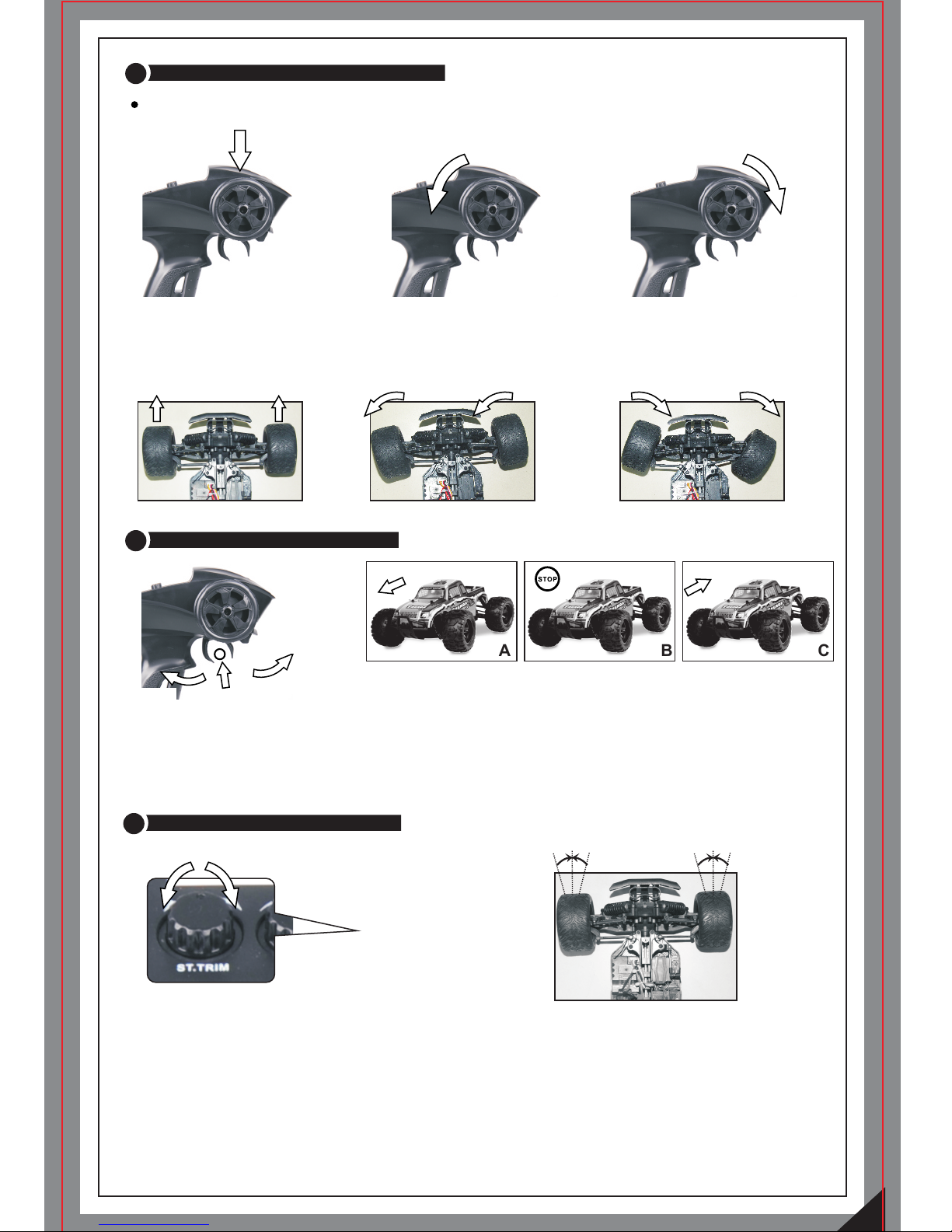
3
CHECK STEERING PER FORMA NCE
Ensure good steeri ng perf ormance.
4
CHECK TRIGGER RESP ONSE
TURN L EF T TURN R IG HT
5
TO TUNE THE STEERING TRI M
CENT RE
CENT RE
PULL IT
BUCK
PUSH I T
FORWARD
A B
C
STEERING TRIM
1) To kee p the car run ning in a
straight lin e , do not move the
control whee l.(Ke ep it centered)
2) Turn the con trol wheel left to
allow y our vehic le to turn left.
3) Turn the con trol wheel right to
allow y our vehic le to turn right.
A. Pull the trigger back to accelerate, release it to decelerate and
push it forward to brake.
B. To stop accelerating your car, release the trigger to Neutral.
C. Pushing the trigger forward a second time activates the reverse
feature.
Gently pull the trigger to allow your car to accelerate slowly. Meantime, tune the steering
trim to align the front wheels.

6
6
TO TUNE THE STEERING DUA L RATE CO NTROL DIAL
Decrease
Increase
STEERING D/R
PRACTICE
BATTERY INSTALLATION
RUNNING PRACTICE
1 2 3 4
This dial adjusts the overall travel of the steering servo. Push the dial forward for maximum
steering. Pull the dial back to reduce the steering level.
- Set the Steering Dual Rate Control Dial to Minimum first. To set the desired steering level
increase it again whilst decelerating your vehicle.
Following the illustrations above to install the Li-Ion battery pack to your car.
1) Remove the batter y cover and install the battery pack in place.
2) Replace the battery cover
3) Lock the battery cover with small body clip. (See figure 3)
4) Connect battery to your radio system. ( See figure 4)
Once you become conformable driving the vehicle, practice driving on the tracks as shown in
the illustration. Keep practicing until you feel comfortable with the steering, throttle and
brake at low speeds.
Once you are feeling comfortable tr y operating on another track.When you have mastered
the basics you will be able to drive at higher speeds with more control.

STOPPING YOUR CAR
1
TURN OFF THE RADIO CON TROLLER
Always switch off the receiver ,and then the radio controller.
2
TURN OFF THE RECEIVE R ON YOUR CAR
CAUTION
3
REMOVE BATTERIES
Do not forgot to remove batteries from your car and radio controller when not in use.
TURN OFF
Power Switch
7
CHARGING THE BATTERY PACK
To be connected
To be connected
To be connected
to the charging
socket.
Charger
(9V, 600mA)
Charger Adapter
Li-ion Battery
Pack
Green Indicator
Red Indicator
-Use only the specified charger (9V,600mA) to charge the Li-Ion battery pack.
- You must use the charger adapter during charging. Connect one side to the charger and
the other side to the battery pack.
- Never charge the battery pack unattended.
- Always remove the batter y pack from the car before charging.
- Always use the battery pack after it is fully charged.
-Charging time is normally around 2.5 hours.
- When the red indicator on the adapter is lit, the battery
is charging.
-When the battery is fully charged the green indicator will be lit.

8
TROUBLESHOOTING
MAINTAINING YOUR CAR
A. The vehicle does
not work at all.
1. Check to see if transmitter and car are on.
2. Check to see if transmitter and receiver are properly bound.
3. Adjust throttle trim on transmitter
4. Replace batteries.
B. The vehicle runs
slow.
1. Replace or charge the battery pack and/or the radio batteries.
2. Make sure the vehicle is geared properly and the pinion
and spur gear are over tightened.
3. Clean all bushings or ball bearings.
4. Check for stripped or dirty gears.
C. The throttle works,
but not the steering.
1. Check if the servo feels jammed, try centering carefully it by hand.
2. Check all the steering linkage for any damage.
D. It steers, but no
throttle control.
1. Adjust the throttle trim.
2. Replace or charge the battery pack and/or the radio batteries.
E. The vehicle runs
noisily.
1. Check gear mesh between spur gear and pinion.
2. Check for stripped and/or dirty gears.
3. Clean and oil bushings or ball bearings.
After running your car, perform the following procedures regularly to maintain your car's
performance.
Inspect your car for any obvious damage.
Check the gears for wear, debris or broken/slipping teeth.
Check the wheels and tighten the wheel screws properly.
Check for loose screws in the chassis.
Check the wiring for frayed or damaged wires or connectors.
Check the steering servo which will wear out over time and require replacement.
Check all batteries.
Keep the chassis clean and free of sand, dust, moisture and any other debris.
Remove and clean the motor if necessary. (Never attempt to re-assemble the motor,
you will damage it and void the warranty).
Clean the car body with a soft lint-free cloth.
Remove all batteries from the car when not in use.

PART LIST-1
1-16 FOUR WHEEL DRIVE VEHICLES
ITEM NO.: 16810
Steering Bush+ St eering Pos t
+E-clip(2mm/4 mm)
ITEM NO.: 16003
Suspension Hing e Pins-Outside
ITEM NO.:16004
Servo L inkag e Set
4PCS
ITEM NO.: 16005
Shock Coil s
ITEM NO.: 16006
Drive Shafts (F r./R r.)
ITEM NO.: 16007
Steering L oad Spr ing
ITEM NO.: 16008
Bra ss Bushes ( 5*8*2.5 mm)
12PCS2PCS2PCS
4PCS
ITEM NO.: 16811
Washer s
ITEM NO.: 16012
6.3 *12.5 *0.2m m(16P )
ITEM NO.: 16013
ITEM NO.: 16014 ITEM NO.: 16015 ITEM NO.: 16016
Chassis
Upper Deck+ Motor M ount
Guard
Servo G uard+ Batt er y Cov er+
Motor Mount
ITEM NO.: 16017
ITEM NO.: 16018 ITEM NO.: 16020
Fro nt Upper Linkage Se t (2P)
Rear Upper Link age Set ( 2P)
Steering Linkag e Set (2P)
Shocks Assembly
4PCS
Diff. Outdrive Cups (4P) +
Wheel Shafts 4P (Fr./Rr.)
Steering Knuckl es (Left/R ight)
+Rear Hub Carri ers (Le ft/ Right)
Fro nt Hub Carriers(L eft /Righ t)
4PCS
Suspension Hing e Pins-Inside
Rear Lower Susp ensio n Arm
(left/Right)
Diff. Gears + Diff. Case
ITEM NO.: 16022
ITEM NO.: 16023 ITEM NO.: 16024
ITEM NO.: 16026
ITEM NO.: 16027 ITEM NO.: 16028
ITEM NO.: 16025
Steering Hub Step S cre ws
12PCS
8PCS
Steering Assemb ly + Antenna
Mount+Serv o Arm +Gear Bush
Fro nt Lower Suspensi on Arm
(left/Right)
ITEM NO.: 16021
Fro nt Gear Box Assembly+
Rear Gear Box Cover
ITEM NO.: H011
Bal l Beari ngs (5* 8*2.5 mm) 6P
ITEM NO.: H030
Bal l Beari ngs (7* 11*3m m) 6P
6PCS
6PCS
O-Ring (Fo r Spur Ge ar)
ITEM NO.: 88021
13PCS
Ball Joint Set ( 3.8m m)
ITEM NO.: 16047
Diff. Assembly- Com plete
(Fr./Rr.)
2PCS

PART LIST-2
1-16 FOUR WHEEL DRIVE VEHICLES
ITEM NO.: 16050ITEM NO.: 16048
Motor RC 380 (25000rmp)
ITEM NO.: 16049
3-in-1 Unit (7.4V, 25A)
ITEM NO.: 16051
Motor Pinion(13 T) + Set Screw
(3*3mm)
ITEM NO.: H021
ITEM NO.: S011 ITEM NO.: S013 ITEM NO.: S016 ITEM NO.:S020
ITEM NO.: S029 ITEM NO.: S061 ITEM NO.: S062
ITEM NO.: S100 ITEM NO.: S120 ITEM NO.: S138
ITEM NO.:S149
ITEM NO.:S091
ITEM NO.: S089
Cou nters unk Self Tapping
Screw 2*15mm
Cou nters unk Screw
2.5*8mm
Set Screw M3*3mm
Cou nters unk Self Tapping
Screw 2.6*8mm
Washer H ead Self Tapping
Screw 2.6*10mm
Cou nters unk Self Tapping
Screw 2.6*6mm
Cou nters unk
Screw 3*10mm
Washer H ead Self Tapping
Screw 2.6*6mm
Washer H ead
Screw 2.5*22mm
Washer H ead
Screw 2.5*8mm
Cou nters unk Self Tapping
Screw 2.6*10 mm
Flange Hea d Self Tapp ing
Screw 2.3*4mm
Flange Head Self Tapp ing
Screw 2*8mm
12PCS
12PCS12PCS12PCS
12PCS1 2PCS12PCS12PCS
12PCS
12PCS12PCS12PCS
12PCS
ITEM NO.: 16057
Small Body Clips A/ B
Small Zip Ties
Body Clip Cu shions
ITEM NO.: P011 ITEM NO.:P100
12PCS8PCS12PCS
Li-ion Bat tery Pa ck (7.4 V,
800mAH)
ITEM NO.:16070
Charger Adaptor
5-Wire Servo ( 19 g)
Wheel Nut Sc rews
(2.6*15mm)
8PCS
8PCS
Motor Moun t Washers
(2.6*6*0 .3mm)
ITEM NO.:16072
ITEM NO.:16073 ITEM NO.: E770
The p annel
and t he
con trol
whe el
in co lor of
bla ck
Receiver Ante nna Pip e
ITEM NO.: P019
2PCS
ITEM NO.:16081
8PCS
Gear Box Washers
(8.2*10.6*0.3 mm)
3-In-1 2 .4G Hz ra dio c ont rol ler
(60 M)
ITEM NO.:16090
Cen tre Drive Sh aft
(Needed for insta lling slipper
clutch)
Fem ale con necto r appli ed
Mal e conne ctor ap plied

11
PART LIST-3
1-16 FOUR WHEEL DRIVE VEHICLES
The images may vary from the received items.
Fro nt Bumpers+Bump er Brace
ITEM NO.:16093 ITEM NO.:16094
Slipper Cl utch Pads/ Disks
Slipper Cl utch Sp ring/Ball
Bearing/ Locks + O -ring + Shim
ITEM NO.: 16091
Slipper Spur Gear U nit
ITEM NO.: 16092
Diff. Pinion Gears
ITEM NO.: 16030
Body Posts ( Fr./ Rr.)
4PCS
Fro nt Shock Tower+Rear Shoc k
Towe r
ITEM NO.: 16033 ITEM NO.: 16034
ITEM NO.: 16042K
Wheel Rims (Fr./Rr.)
TRU GG Y / MO NS TE R TRU CK
ITEM NO.: 16043 ITEM NO.:16044K
Flame Ti res +Spong e (Truggy) Wheels Com plete(Trugg y)
TRU GG Y
ON LY
TRU GG Y ON LY
ITEM NO.: 16045
MO NS TE R
TRU CK
ON LY
TIRES+SP ONGE (M onsterTruck)
ITEM NO.: 16046K
Wheels Com plete(Monster
Truck)
ITEM NO.: 16053
AM ER IC A STAN DA RD
Charger (AMERICA STANDARD),
9V, 600mA
ITEM NO.: 16037
ITEM NO.: 16035
Wheel Hex.
Fro nt Rear
MO NS TE R
TRU CK
ON LY
ITEM NO.: 17003 ITEM NO.: 17002 ITEM NO.:17001 ITEM NO.: 17004
Trem or ST truc k Body (B lue) Tremor ST truc k Body (Red)
Tremor SG truggy B ody (Bl ue) Tremor SG truggy B ody (Green)
Fro nt Bumper(Buggy), wh ich
can be an optional pa rt to tru ck
or truggy
Rear Bumper(Trug gy/ Monster
Truck)
ITEM NO.: S153
Cou nters unk Screw
2.5*5mm
12PCS

12
The images may vary from the received items.
OPTIONAL PARTS
1-16 FOUR WHEEL DRIVE VEHICLES
Alum.C apped Oil Filled Sh ocks.
+ Ball Joints (Fr./Rr.)
Brushless Motor Brushless ESC
ITEM NO.: 16805
Motor Cool ing Heat Sink
ITEM NO.: 16804
Bal l Beari ngs (8* 12*3. 5mm) 6P
6PCS
ITEM NO.: 16806
Bru shles s ESC Coo lin g Fan +
Mou nting S crews (4P )
ITEM NO.: E775
ITEM NO.: E710
Independent 2.4 GHz Receiver
2.4 GHz rad io co ntr oll er (over
150 M)
The p annel
and t he
con trol
whe el
in co lor of
tit anium
ITEM NO.: 16800 ITEM NO.: 16802 ITEM NO.:16803
Warning: If you perform a drive train upgrade, replace the entire system (Such as motor,
ESC/receiver unit and the like) so that all components are properly matched.
Any malfunction incurred by custom modification will void your warranty.

13
UNITS ASSEMBLY VIEW
SHOCK ASSEMBLY
16005
16024
16024
SERVO INSTALLATION
16018
16051
16025
FINISHED
FINISHED
88021
S149
DIFF. ASSEMBLY (Front)
16026
16020
16020
16020
16020
16020
16020
16026
16804
16804
16811 (6.3 *12.5*0.2mm)
16811 (6.3 *12.5*0.2mm)
FINISHED
16092
H030
S011

14
DIFF. ASSEMBLY (Rear)
16026
16020
16020
16020
16020
16020
16020
16026
16804
16804
16811 (6.3 *12.5*0.2mm)
16811 (6.3 *12.5*0.2mm)
FINISHED
S011
16092
H030
16007
88021
16025
16025
16025
16810
16025
16810
S013
16810
E-Clip(4 mm) is app lied
here after th e kit is
assemble d.
E-Clip(2 mm) is app lied
here after th e kit is
assemble d.
Steering Assembly View
locked with S15 3 to the chass is
fro m the bottom

15
H030
H030
16092
16090
SLIPPER CLUTCH SET ASSEMBLY
16093
16091
16093
16093
16093
16094
16094
16094
16094
TI PS:
Use needle-nose pliers to adjust the slipper clutch
set as shown in the picture. Place the car with its
four wheels landing on the ground.
1) Hold the nut by the pliers (as shown in the
picture), moving the car backwards gently by hand
to loosen the slipper clutch.
2) Hold the nut by the pliers (as shown in the
picture), moving the car forward gently by hand to
tighten the slipper clutch.
16094 (O-ring)
5* 3*1
16094 (Shim)
4* 8*0. 5

1605 0
1604 9
1604 8
1601 5
1601 8
1605 7(Lock ed with M 3*3 Set S crew)
1601 8
8
1601 8
1601 7
1602 5
1603 7
1602 7
1602 3
8802 1
1600 6
1601 7
1601 2
1602 3
1602 3
1600 6
1602 3
8802 1
1602 8
1602 7
1603 7
1602 1
1600 3
1600 4
1600 3
1600 4
1600 4
1600 3
1602 2
1602 2
1603 4
1600 6
1600 6
1602 7
1602 6
1602 6
1602 6
1602 3
1603 7
1602 3
1602 7
1604 3
1603 7
1607 2
1607 2
1607 2
1607 2
1602 8
1602 6
1602 1
1600 4
1600 3
1600 8
16 11
(6.3 *12.5 *0.2m m)
S062
S062
S062
S062
S062
S062
S062
S062
S020
S020
S020
S013
S013
S013
S013
S013
S013
S029
S091
S091
S091
S091
S100
S100
S089
S029
S029
S029
S029
S029
S120
S061
S013
S061
S138
S138
S020
S100
S100
1604 2W(16 042K)
1604 3
1604 2W(16 042K)
1604 2W(16 042K)
1604 3
1604 3
1604 2W(16 042K)
1603 3
1603 3
S029
S029
S029
1603 0
S138
S138
1603 0
S138
S138
S020
S020
1603 5
1603 5
1603 5
EXPLODED VIEW
OFF ROA D TRUGG Y
1-16TH SCALE 4W D ELECTRIC
8802 1
1600 8
1600 8
1602 8
1600 8
1600 8
H030
H030
1609 2
1601 7
S153
Locked
with S15 3
Locked
with S01 3

1605 0
1604 9
1604 8
1601 5
1601 8
1605 7(Lock ed with M 3*3 Set S crew)
1601 8
8
1601 8
1601 7
1602 5
1603 7
1602 7
1602 3
8802 1
1601 7
1601 2
1602 3
1602 3
1600 6
1602 3
8802 1
1602 8
1602 7
1603 7
1602 1
1600 3
1600 4
1600 3
1600 4
1600 4
1600 3
1602 2
1602 2
1603 4
1600 6
1600 6
1602 7
1602 6
1602 6
1602 6
1602 3
1603 7
1602 3
1602 7
1604 5
1603 7
H030
1607 2
1607 2
1607 2
1607 2
1602 8
1602 6
1602 1
1600 4
1600 3
1600 8
(or H01 1)
16 11
(6.3 *12.5 *0.2m m)
S062
S062
S062
S062
S062
S062
S062
S062
S020
S020
S020
S013
S013
S013
S013
S013
S013
S029
S091
S091
S091
S091
S100
S100
S089
S029
S029
S029
S029
S029
S120
S061
S013
S061
S138
S138
S020
S100
S100
1604 2W(16 042K)
1604 5
1604 2W(16 042K)
1604 2W(16 042K)
1604 5
1604 5
1604 2W(16 042K)
1603 3
1603 3
S029
S029
S029
1603 0
S138
S138
1603 0
S029
S029
S020
S020
1603 5
1603 5
1603 5
EXPLODED VIEW
OFF ROA D MONSTER TRUCK
1-16TH SCALE 4W D ELECTRIC
8802 1
1600 8
1600 8
1600 8
1600 8
1600 8
H030
1609 2
1600 6
1601 7
S153
Locked
with S15 3
Locked
with S01 3

This product is not a toy. It is not suitable for users under 14 years old unless supervised
by an adult.
Never attempt to re-assemble any electronic components. These have been carefully
calibrated at the factory.
WARNINGS
Please completely read and understand the entire manual before using, assembling and/or
disassembling your remote controlled car.
-Read and understand all instructions carefully before use and assembly/disassembly.
-Do not run your vehicle on public roads or any area where you may encounter pedestrian or vehicle traffic.
-Do not operate in a congested area or in crowds.
-Do not operate your vehicle with obstructed line of sight, at night, or near water.
-Your vehicle is radio controlled. Radio waves are subject to interference. Radio interference can cause
loss of control of your vehicle.
-Take care not to injure yourself while using tools to adjust or upgrade your vehicle.
 Loading...