


ASSEMBLY INSTRUCTION
=
INSTALLATION AREA
N :R
+
A
C
B
Caution : Please read instructions thoroughly before unpacking assembly parts.
Sharp, exposed staple tips can cause injury, therefore, for your protection,
!
please remove any exposed staples used in packing.
1. We recommend that you should assemble this product with the assistance of another person ;
this will make assembly easier, and will help to eliminate damage to the product or injury to
persons during assembly.
2. Be sure to check all packing materials carefully for small parts that may have come loose inside
the carton during shipment.
3. Please do not over tighten screws or bolts.
4. Please put all parts on a non - abrasive floor before assembly. and follow the assembly step to
assemble your newly purchased product correctly and efficiently .
Drawer N Q & N R are identical & compatible, to each other regardless left or right.
During assembly, do not tighten any hardware until the complete unit has beeb assembled.
+
N :R
N :Q
2 PERSON
installation recommended
20 - 25
mins
20 - 25
minutes for installation
PAGE 1 OF 11

BOX 1
Box of Headboard & Footboard
Hardware List
N A N B
Headboard x 1
255 x 1420 x 1593 mm
N C(L)
Headboard Leg (L) x 1 Headboard Leg (R) x 1
N E
Drawer Support Rail 2 x 4
20 x 40 x 633mm
Footboard
x 1
42 x 570 x 1591mm
N C(R) N D
N F
Support Leg 2 x 1
30 x 30 x 95mm
BOX 2
Box of Side rail
N H
Side Rail x 2
39 x 570 x 2060mm
N I
Bed Slat x 3
18 x 45 x 1545mm
N A1
Headboard Drawer x 2
Triangle Support Panel
-9 x 200 x 200
N G
Support Leg 3 x 1
30 x 30 x 107mm
N J
F/Board Drawer Frame x 1
40 x 220 x 1545mm
N 1
Flat Head Chipboard
x 8
Screw
m4 x 32mm RBW
x 2
N 5
Spring Washer x 6
1/4" RBW
N 2
Pan Head Chipboard
x 8
Screw
m3.5 x 20mm BLK
N 6
Flat Washer x 6
1/4" ID x 13mm OD
BLK
N 3
JCBC Bolt x 4
m6 x 35mm
BLK
N 7
Allen Key x 1
m4 x 110mm BLK
N 4
JCBC Bolt x 2
m6 x 50mm
BLK
Hardware List
N 8
Flat Head Chipboard
x 16
Screw
m4 x 32mm RBW
N 9
Pan Head Chipboard
Screw
x 27
m3.5 x 20mm BLK
N 10
JCBC Bolt x 15
m6 x 35mm
BLK
N 11
JCBC Bolt x 6
m6 x 50mm
BLK
N K
Concealed Panel x 5
9 x 295 x 2040mm
N N
Supprt Leg 1 x 5
30 x 30 x 518mm
N L
H/Board Back Support 1 x 1
19 x 30 x 1559mm
N O
H/Board Back Support 2 x 1
18 x 45 x 1559mm
BOX 3 & 4
Box of Parts & Hardware
N Q
Drawer 1 x 4
Drawer 2 x 2
N R
N M
Drawer Support Rail x 1
30 x 30 x 1545mm
N P
Bed Slat With Marking x 2
18 x 45 x 1545mm
N 16
Handle x 8
N 12
Spring Washer x 15
1/4" RBW
N 17
Truss Head M.
Screw Handle
m4 x 48mm BLK
x 4
N 13
Flat Washer x 15
1/4" ID x 13mm OD
N 18
Truss Head M.
Screw Handle
m4 x 50mm BLK
BLK
x 4
N 14
Z - Bracket x 1
N 15
Allen Key x 1
m4 x 110mm BLK
PAGE 2 OF 11

A
Headboard
Assembly
Installation
Rotate the Headboard (A) down and
turn to back.
Attach and tighten the Headboard Leg
L/R (C) to the Headboard (A).
Box 1 : N A Box 1 : N C(L) + N C(R)
N A
N C(L)
Right
Left
N C(R)
Right
Left
Insert Spring washer (5) , Flat Washer (6) , tighten JCBC bolt (3) by using
an Allen Key (7).
N A
Box 1 : N 3 + N 5 + N 6 + N 7
Insert Spring washer (5) , Flat Washer (6) , tighten JCBC bolt (4) by using
an Allen Key (7).
Box 1 : N 4 + N 5 + N 6 + N 7
Back
N 7 N 3 N 5 N 6
N 3
N 4
x4
N 4N 3
N 7N 4N 5N 6
x2
PAGE 3 OF 11
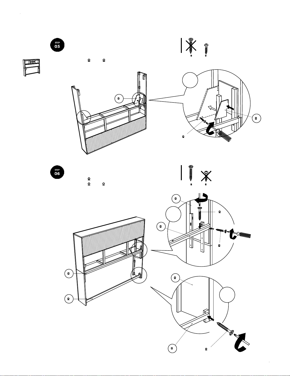
A
Attach and tighten the triangle Support Panel (D) to the
Headboard and tighten the Panhead screw (2) using
screw driver . (Not included)
Box 1 : N D + N 2
N 2N 1
Headboard
Assembly
Installation
N D
Attach Headboard Back Support (L) & (O) as picture shown. Tighten
the CSK screw (1) using a screw driver. (Not included)
Box 1 : N 1
Box 2 : N L + N O
6.1
x6
x8
N D
N 2
N 2N 1
N C
N 1
N L
N O
N L
6.2
N C
N O
N 1
x2
N 1
PAGE 4 OF 11

B
Attach the Side Rail (H) to the Headboard Leg L/R (C). Insert Spring
Washer (12) , Flat Washer (13) , tighten JCBC (10) using
an Allen Key (15).
Box 2 : N H + N 10 + N 12 + N 13 + N 15
N 11N 10
N C
Footboard
Structure
Assembly
Installation
N C
N H
Attach the Side Rail (H) to the Footboard (B). Insert Spring Washer (12) ,
Flat Washer (13) , tighten JCBC (10) using an Allen Key (15).
Box 1 : N B
Box 2 : N 10 + N 12 + N 13 + N 15
N B
x4
N H
x4
N 13
N 12
N H
N 10
N 15
N 11N 10
N H
N B
N 13
N 12
N 10
N 15
PAGE 5 OF 11

B
Footboard
Structure
Assembly
Installation
Attach Support Leg (G) to the Footboard Drawer Frame (J). Insert Spring
Washer (12) , Flat Washer (13) , & tighten JCBC (10) using an Allen Key(15).
Box 1 : N G
Box 2 : N J + N 10 + N 12 + N 13 + N 15
N J
N G
N 11N 10
N 15
N 10
N 12
N 13
x1
N J
N G
Attach the Footboard Drawer Frame (J) to the Side Rail (H). Insert Spring
Washer (12) , Flat Washer (13) , tighten JCBC (10) using Allen Key (15).
Box 2 : N 10 + N 12 + N 13 + N 15
N H
N 11N 10
N J
x2
N HN J
N 13N 12N 10N 15
PAGE 6 OF 11

B
Attach the Drawer Support Rail (E) to the Footboard (B) using CSK Screw (8)
and tighten with Screw Driver. ( Not included)
Box 1 : N E
Box 2 : N 8
N 9N 8
x4
Footboard
Structure
Assembly
Installation
N E
N B
N E
Attach the Drawer Support Rail (E) to the Footboard Drawer Frame (J). Insert
Spring Washer (12), Flat Washer (13) & tighten JCBC Bolt (10) using an Allen
Key (15).
Box 2 : N 10 + N 12 + N 13 + N 15
N 8
N B
N 11N 10
N J
N 15
N 10
N 12
N 13
x4
N EN J
PAGE 7 OF 11

B
Footboard
Structure
Assembly
Installation
Attach Support Leg 2 (F) to the Drawer support Rail (M). Tighten
JCBC Bolt (11) using an Allen Key (15)
Box 1 : N F
Box 2 : N M + N 11 + N 15
N M
N 11N 10
N 15
N 11
N F
Attach Drawer Support Rail (M) to the Side Rail (H) using CSK Screw (8) and
tighten with Screw Driver. ( Not included)
Box 2 : N 8
x1
N 8
N M
N F
N 9N 8
N H
N M
N M
x2
PAGE 8 OF 11

B
Footboard
Structure
Assembly
Installation
Attach Bed Slat (I) & (P) to the Bed Slat Support (N) . Tighten JCBC Bolt (11)
using an Allen Key (15). ( Loosen and tighten the Adjuster to
stability of bed)
Box 2 : N I + N N + N O + N P + N 11 + N 15
x3
N 11N 10
N 15
N 11
N I
N N
N P
N N
Attach Z-Bracket (14) to the Bed Slat Support (N) and Support Leg 2 (F). Use
Panhead Screw (9) and tighten with Screw Driver. ( Not included)
Box 2 : N 9 + N 14
x2
N I
N N
N 15
N 11
N P
N N
N 9N 8
N N
N F
N F
N 9
N P
N I
N I
N I
N P
x2
N N
N 14
PAGE 9 OF 11

C
Slide Drawer - 2 (R) into position over Draer Support Rail -1 (M). Then slide Drawer - 1 (Q)
into position over Drawer Support Rail - 2 (E). Adjust the adjuster for alignment of drawer box.
Box 3 : N Q + N R
N E
Conceal
Panel & Drawer
Assembly
Installation
N M
N R
N Q
Install the handle (16) in the front or drawer (R). Tighten the Handle Screw (18) using Screw
Driver. (Not included)
Install the Handle (16) in front of drawer (Q). Tighten the Handle Screw
(17) using Screw Driver. (Not included)
Then Push together the Slide Rail (H) with Bed Slat (I) & tighten with
CSK Screw (8) by using Screw Driver. (Make sure the center of Bed Slat (I) is aligned with the
marked line as shown).
Box 2 : N 8
Box 3 : N 16 + N 17 + N 18
N R
N 18N 17
N 18N 17
N 9N 8
x4
N 18
N 16
N R
N Q
x10
N 8
N H
Marked Line
N I
N 17
N 16
x4
PAGE 10 OF 11

C
Conceal
Panel & Drawer
Assembly
Installation
Attention! Screw on this markings on concealed panel slat (K).
Realign the Concealed Panel Slat (K) as shown.
Box 2 : N K
Attach Concealed Panel (K) over the Bed Slat (I) using Panhead
Screw (9) and tighten with Screw Driver. ( Not included)
Box 2 : N 9
N K
N 9
N K
N 9N 8
N I
x25
PAGE 11 OF 11
 Loading...