

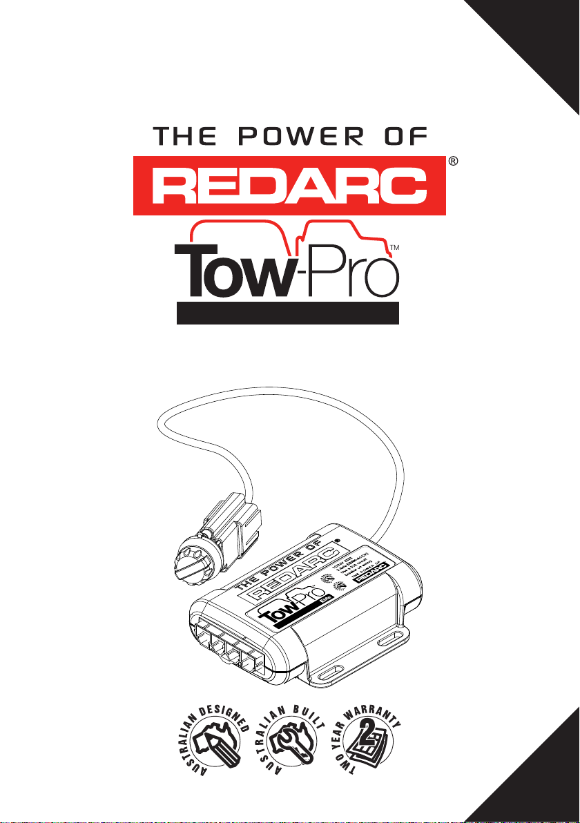
Page 1
AL-KO ESC &
DEXTER DSC
APPROVED*
PROPORTIONAL
with ACTIVE CALIBRATION
Elite
Electric Trailer Brake Controller
Page 2
TOW-PRO™ ELITE (EBRH-ACCV2) TRAILER BRAKE CONTROLLER
The Tow-Pro™ Elite is an electric trailer brake controller designed to suit most common
trailer braking applications whilst requiring minimal dash space and being simple to install
and operate.
The Tow-Pro™ Elite offers selectable Proportional or User Controlled trailer braking modes
allowing the user to choose the braking style depending on the road or terrain conditions,
vehicle type, or driver preference.
The Tow-Pro™ Elite features Active Calibration which constantly monitors the direction of
travel and will even calibrate with no trailer attached whilst maintaining the ability to mount
in any orientation.
The unit is able to operate both electric and electric/hydraulic trailer brakes and will operate
from either 12V or 24V vehicle systems without the need for manual selection or extra
components/ wiring. The unit is ADR compliant when installed as directed and is approved
for use with AL-KO ESC and Dexter DSC sway control systems.
WARNINGS & SAFETY INSTRUCTIONS
SAVE THESE INSTRUCTIONS - This manual contains IMPORTANT SAFETY INSTRUCTIONS for
the
Tow-Pro™ Elite
Brake Controller.
DO NOT OPERATE THE CONTROLLER UNLESS YOU HAVE READ AND UNDERSTOOD THIS
MANUAL AND THE CONTROLLER IS INSTALLED AS PER THESE INSTALLATION INSTRUCTIONS.
ENSURE THAT YOUR TRAILER BRAKES ARE INSTALLED AND ARE OPERATING CORRECTLY:
IMPROPERLY INSTALLED AND/OR FAULTY TRAILER BRAKES CAN CAUSE ERRATIC VEHICLE OR
TRAILER BEHAVIOUR WITH THE POTENTIAL TO CAUSE A ROAD ACCIDENT. FOR THIS REASON,
IT IS OF UTMOST IMPORTANCE THAT YOUR TRAILER BRAKING SYSTEM BE INSTALLED/
MAINTAINED BY A QUALIFIED INSTALLER.
ALWAYS CHECK BRAKES AT LOW SPEED EACH TIME A TRAILER IS ATTACHED TO YOUR
VEHICLE.
1. Ensure that the Tow-Pro™ Elite is mounted securely in a fixed location. Failure to
mount securely will result in inaccurate braking force measurements and incorrect
braking of the trailer.
2. Ensure that the Tow-Pro™ Elite is installed inside the vehicle cabin and away from any
environmental conditions that may cause damage, including engine heat, submersion
in water, salt spray and humidity. Exposure to these conditions may cause damage to
the unit’s circuitry and may cause erratic trailer braking.
SAL.FOR.Instruction Manual.EBRH-ACCV2 – Version 4
1
Page 3

WARNINGS & SAFETY INSTRUCTIONS
3. A Fuse or Circuit Breaker of appropriate rating must be installed to protect the vehicle
system. Please refer to the installation instructions on page 7 for specific instructions
on where to install the Fuse or Circuit Breaker and for appropriate Fuse or Circuit
Breaker rating. The Fuse or Circuit Breaker must be installed as close as possible to
the battery.
4. Ensure the remote head push-button activates correctly when installed into surfaces
with a thickness greater than 3.0mm. Failure to activate correctly would result in not
being able to activate the override function or change modes.
5. Ensure that the cable used to install the Tow-Pro™ Elite is of adequate gauge to
supply the required current to operate the trailer brakes. Incorrect wiring can result in
overheated wires or excessive voltage drop and may cause injury to persons, damage
to the Tow-Pro™ Elite and/or damage to property.
6. The Tow-Pro™ Elite is suitable for all trailers with electric brakes on up to three axles.
Note that for trailers above 4.5t gross, special testing is required under Australian
Design Rules. For these trailers, please consult with an automotive safety engineer
before using the Tow-Pro™ Elite.
1. Ensure that a correct grounding point is used. Vehicles often have ungrounded
metal reinforcements under the dash and these points are not suitable grounds. Bad
grounding of the unit will result in poor or no operation.
2. The Tow-Pro™ Elite does not act as a trailer lights voltage converter. The Tow-Pro™
Elite is designed to operate the trailer brake lights under certain conditions. If the
trailer brake lights require a different voltage to the input from the vehicle, damage to
the trailer brake lights may result.
3. When installing the Tow-Pro™ Elite Remote Control to a thin panel, washers are
recommended to reinforce the structure of the panel.
4. Do NOT exceed Tow Vehicle and Trailer weights and specifications. Failure to abide by
the towing regulations, including maximum loads, may result in a fine, or in case of
an accident, refusal of the insurance claim, and the possibility of further legal action.
If the tow vehicle or trailer’s maximum load is exceeded, police and transport
authorities have the power to order the combination off the road until the issue is
corrected. This may necessitate leaving the trailer on the side of the road while a
vehicle with suitable towing capacity is sourced or the trailer load is reduced. Please
contact your local authorities for further information.
2
Page 4

CONTENTS
Table of Contents Page
1 - Specifications 3
2 - Installation 5
2.1 - Mounting the main unit 5
2.2 - Wiring the brake controller 6
2.2.1 Red Wire (Vehicle Brake light) Connection 6
2.2.2 Wiring Diagrams 7
2.3 - Mounting the Remote Head 8
2.4 - Active Calibration 9
3 - Operation 10
3.1 - Adjusting the Braking Force 10
3.2 - Manual Override 10
3.3 - Operating Modes 11
3.3.1 - Proportional Mode (Blue LED) 11
3.3.2 - User Controller Mode (Green LED) 11
3.3.3 - Changing Modes 12
3.4 - Park Brake Feature 12
3.5 - Electric / Hydraulic Brakes 13
3.6 - 24V Vehicle Systems 13
3.7 - Visual User Guide 14
3.8 - LED Indication 15
3.9 - Troubleshooting 16
4 - Periodic Maintenance / Checks 19
5 - Frequently Asked Questions 20
6 - Notes 21
7 - Two Year Product Warranty 22
SPECIFICATIONS
Part Number EBRH-ACCV2
Operating Voltage 9V - 32V
Nominal Input System Voltage 12V 24V
Brake Input Signal Voltage OFF: 0V
ON: +12V nominal
OFF: 0V
ON: +24V nominal
Brake Coil Voltage 12V 12V
Max. Trailer Axles 3 Axles 3 Axles
Nominal Current Draw 18A 18A
Max. Rated Current 25A 30A
Standby Current <10mA
Operating Temp -20°C to +60°C
Weight 200g
Warranty 2 years
3
Page 5
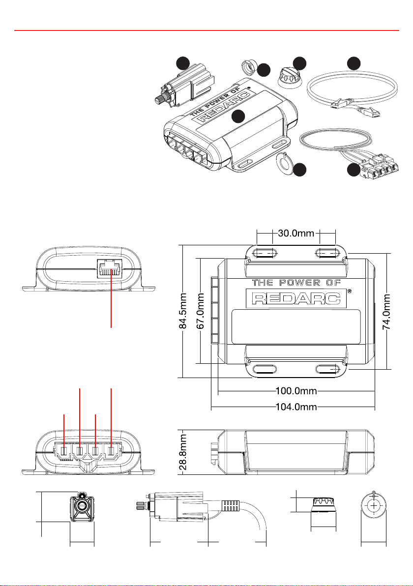
1 SPECIFICATIONS
Kit Contents
1. Remote Head Assembly
2. Main Unit
1
3
4
6
3. Remote Head Nut
4. Remote Head Knob
5. Remote Head Bezel
6. RJ45 Remote Head Cable (1m)
7. Main Unit Wires & Connector (0.5m)
Dimensions & Connection
Remote Head
Connection
Brake
Output
(BLUE)
Brake
Lights
(RED)
Input
Power
(BLACK)
Ground/
Earth
(WHITE)
2
5
10.0mm 10.0mm
7
23.7mm
19.0mm
46.5mm
4
(Recommended)
43.5mm
11.5mm
20.0mm
20.0mm
Page 6
2 INSTALLATION
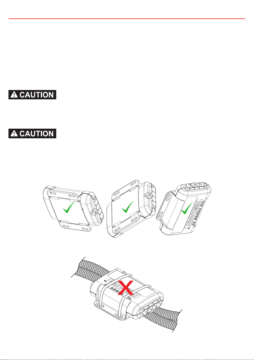
2.1 Mounting the main unit
The Tow-Pro™ Elite should be mounted inside the vehicle cabin using either M4 screws
or other secure fitting methods at the mounting points provided. It is essential to mount
the unit in a location which allows access to the intended remote head location.
The Tow-Pro™ Elite can be mounted in any orientation as long as the installation is
secure and the main unit cannot move or change orientation once installed. A change of
orientation will affect the system calibration.
Ensure that the Tow-Pro™ Elite is mounted securely in a fixed location. Failure to mount
securely will result in inaccurate braking force measurements and incorrect braking of
the trailer.
Ensure that the Tow-Pro™ Elite is installed inside the vehicle cabin and away from any
environmental conditions that may cause damage, including engine heat, submersion in
water, salt spray and humidity. Exposure to these conditions may cause damage to the
unit’s circuitry and may cause erratic trailer braking.
Any Secure Orientation OK
Do Not Mount to Cables / Wiring Looms
5
Page 7

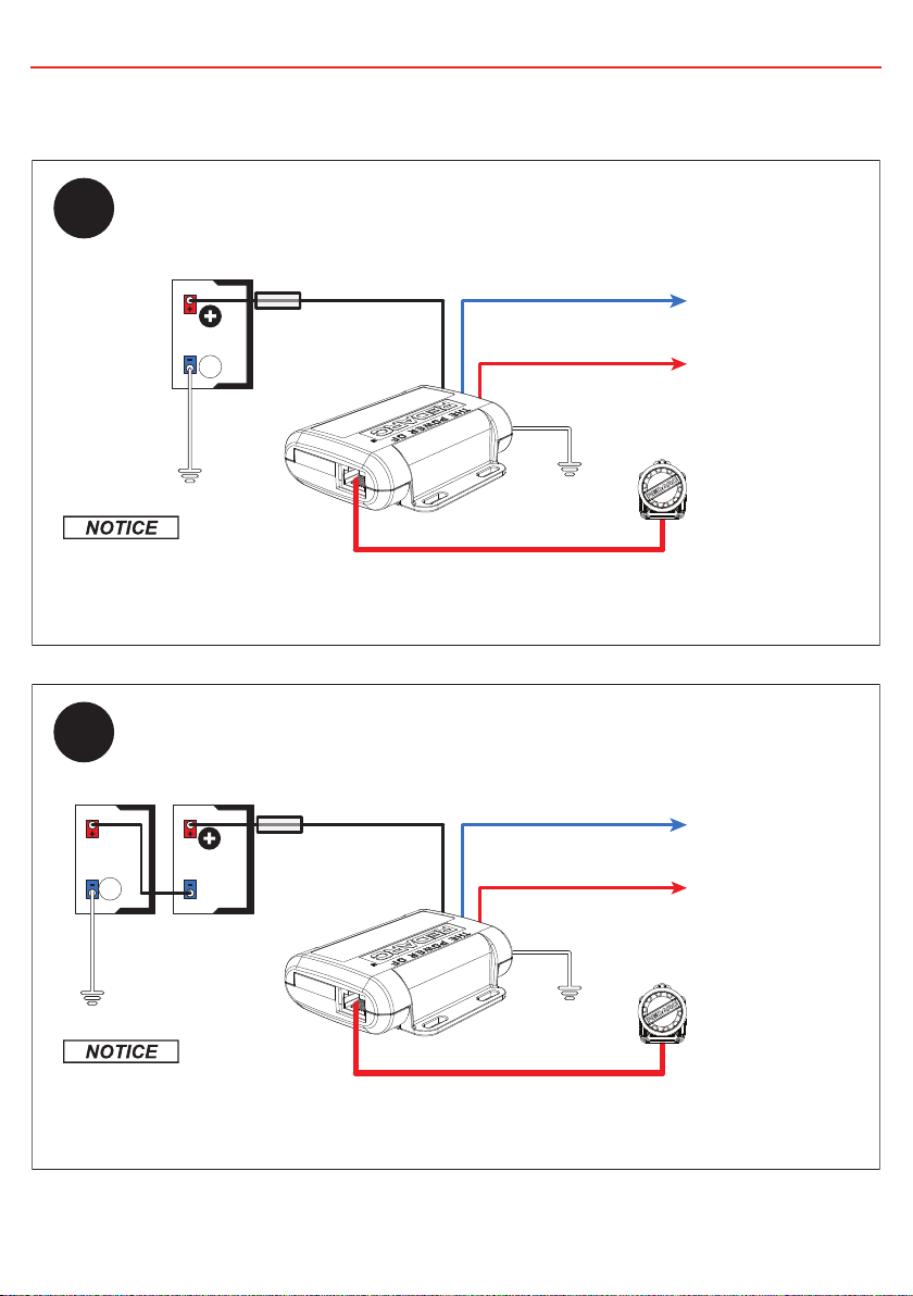
2 INSTALLATION
2.2 Wiring the brake controller
A Fuse or Circuit Breaker of appropriate rating must be installed to protect the vehicle
system. Please refer to the installation instructions on page 7 for specific instructions on
where to install the Fuse or Circuit Breaker and for appropriate Fuse or Circuit Breaker
rating. The Fuse or Circuit Breaker must be installed as close as possible to the battery.
Ensure that the cable used to install the Tow-Pro™ Elite is of adequate gauge to supply
the required current to operate the trailer brakes. Incorrect wiring can result in overheated
wires and may cause injury to persons, damage to the Tow-Pro™ Elite and/or damage to
property.
The Tow-Pro™ Elite does not act as a trailer lights voltage converter. The Tow-Pro™ Elite
is designed to operate the trailer brake lights under certain conditions. If the trailer brake
lights require a different voltage to the input from the vehicle, damage to the trailer brake
lights may result.
2.2.1 Red Wire (Vehicle Brake light) Connection
The requirements for a suitable connection of a brake controller trigger wire are quite
specific. This connection point must:
• Provide battery voltage output while the vehicle brakes are applied.
• Have 0 volts output while the vehicle brakes are not applied
• Accept battery voltage input when the brake controller manual over-ride is operated
and illuminate at least the trailer brake lights.
• Accept the battery voltage input as above without causing any damage, spurious
vehicle operation or erroneous fault indication.
A relay should not be installed to drive the red wire as this would prevent the override
feature from working and may introduce dangerous voltage spikes.
For many vehicles, the brake light terminal of the trailer lighting socket provides a suitable
connection, however this is not necessarily suitable for all vehicles. Unfortunately REDARC
cannot recommend where to make this connection on a specific vehicle’s OEM wiring. For
further information contact the vehicle manufacturer.
6
Page 8
2 INSTALLATION
2.2.2 Wiring Diagrams
12V
INPUT
25A Fuse or
30A Circuit Breaker
(CBK30-EB)
12V Vehicle
Start Battery
-
Ground
The Input Power (Black) wire should be
connected directly to the positive terminal of
the start battery via a Fuse or Circuit Breaker
and not through an Ignition source.
24V
INPUT
25A Fuse or
30A Circuit Breaker
(CBK30-EB)
-
24V Vehicle
Start Battery
Ground
The Input Power (Black) wire should be
connected directly to the positive terminal of
the start battery via a Fuse or Circuit Breaker
and not through an Ignition source.
3.0mm²
3.0mm²
Black
Black
Blue
Blue
Red
Red
3.0mm²
1.25mm²
1.25mm²
White
3.0mm²
1.25mm²
1.25mm²
White
To 12V Trailer
Brakes
To 12V Vehicle
Brake Light trigger
(refer to section 2.2.1)
Dash mount
controls for
Tow-pro.
To 12V Trailer
Brakes
To 24V Vehicle
Brake Light trigger
(refer to section 2.2.1)
Dash mount
controls for
Tow-pro.
7
Page 9

2 INSTALLATION
2.3 Mounting the Remote Head
The Tow-Pro™ Elite remote head is designed to be mounted at a distance from the main
unit, allowing for a neat, convenient installation and not impeding on lower leg airbags or
driver leg room. The Tow-Pro™ Elite remote head is designed to be mounted on or around
the vehicle dashboard and when installed correctly, complies with Australian Design Rule
(ADR) 21, which sets requirements for devices mounted on the dashboard. The Tow-Pro™
Elite remote head can be mounted directly to the dashboard, to the centre console or
through a spare knock-out switch panel and requires only two holes to be drilled as per
the below diagram.
*2.0 - 3.0mm
Applying the Knob
Ø3.5mm
7.5mm
Ø10.0mm
(drill pilot
hole first
or use a
spade bit)
Turn shaft fully
anti-clockwise
Apply knob with
‘0’ aligned with
the level marker
on the bezel.
Ensure the remote head push-button activates correctly when installed into surfaces with
a thickness greater than 3.0mm. Failure to activate correctly would result in not being
able to activate the override function or change modes.
Torque to 0.8Nm
8
Page 10

2 INSTALLATION
2.4 Active Calibration
When the unit is first powered, Active Calibration must first become confident in
the vehicle direction of travel. Until this time the LED will flash Blue/Green.
Time Time
During Calibration: Once Calibrated:
Active Calibration constantly monitors the vehicle’s direction of travel and allows the
Tow-Pro™ Elite to ‘learn’ and continuously confirm its mounting orientation. This process
occurs whilst the vehicle is moving and the brake is applied and will occur with or without
a trailer connected.
When the Tow-Pro™ Elite is first installed it will begin learning its mounting orientation
through Active Calibration as soon as you start driving, at this point Proportional Mode is
selected but not yet fully operational.
Until the Tow-Pro™ Elite has determined its mounting orientation the unit will function as
if in User-Controlled mode, this is indicated by the LED glowing green with blue flashes.
As the Tow-Pro™ Elite becomes more confident of its direction of travel the length of the
Blue flash will increase, to the point that the LED is solid Blue which indicates it is now
operating completely in Proportional mode.
Under normal driving conditions the Tow-Pro™ Elite will learn its mounting orientation
within 20 brake applications. Note that the braking must be perceptible (applying the
brake while stopped will not assist calibration).
If power is disconnected (for example, if the vehicle battery is changed) calibration
memory will be lost and the unit will recalibrate itself using active calibration. This is
similar to a radio losing its clock or preset station memory.
If no trailer is connected, Active Calibration will occur as normal without any indication
from the LED. The LED will already be Blue when the trailer is connected. Essentially,
whether a trailer is connected or not, just drive normally and Active Calibration will ensure
the Tow-Pro™ Elite learns the correct direction of travel.
9
Page 11

3 OPERATION
3.1 Adjusting the Braking Force
In both modes the braking level can be adjusted to
suit varying trailer loads, braking requirements or
user comfort by adjusting the control knob on the
0
10
2
8
4
6
remote head.
The lower end of the scale (below level 5) should
be used as a starting point and adjusted accordingly
once braking requirements are established.
If a lighter braking level is required, turn the control knob to a lower number (anti-clockwise)
to reduce the trailer braking force. Similarly, turn the gain control knob to a higher number
(clockwise) to increase the trailer braking force.
The braking level will be indicated by the LED changing to a shade of RED when the
brakes are applied. The higher the braking level, the more RED the LED will glow.
A setting of ‘0’ will result in no trailer braking output.
3.2 Manual Override
Pressing the gain control knob whilst driving will
apply the manual override brake. The manual
override brake will apply the trailer brakes only; if
wired correctly will also apply the trailer brake lights
and will turn the LED indicator a shade of RED.
Depending on the vehicle wiring it may possibly also
apply the vehicle brake lights. The manual override
is designed to be used when the trailer brakes need
to be applied without the vehicle brakes, such as
correcting trailer ‘sway’ whilst travelling.
In Proportional mode the manual override will apply the trailer brake to a level equivalent
to ‘light’ vehicle braking.
In User Controlled mode the manual override will apply the trailer brakes to the level set
on the gain control knob.
In both modes the braking force can be adjusted by turning the gain control knob, either
higher or lower, even whilst applying the manual override brakes.
Manual override should not be used in place of the regular vehicle brakes.
10
Page 12

3 OPERATION
3.3 Operating Modes
The Tow-Pro™ Elite offers two modes of operation - Proportional and User Controlled.
On the first application of power to the black wire, the Tow-Pro™ Elite will start-up in
Proportional mode. Every time a trailer is connected, the Tow-Pro™ Elite will start up in
the mode that was last selected (provided the black wire has remained connected to
power/battery positive).
3.3.1 Proportional Mode (Blue LED)
If the status indication LED on the control knob is glowing
BLUE, the Tow-Pro™ Elite is in Proportional Mode.
In Proportional Mode, the Tow-Pro™ Elite will apply the trailer
brakes at a level proportional to the vehicle deceleration.
The control knob setting, 0 to 10, will set the brakes from
a lighter to a heavier trailer brake application. Simply put,
the harder the vehicle brakes are applied, the harder
the trailer will brake. This mode is designed for highway
travelling or everyday use and requires minimal input from
the user whilst travelling.
3.3.2 User Controlled Mode (Green LED)
If the status indication LED on the control knob is glowing
GREEN, the Tow-Pro™ Elite is in User Controlled Mode.
In User Controlled Mode, the Tow-Pro™ Elite will apply the
trailer brakes to the level set by the user on the gain control
knob. The control knob setting, 0 to 10, will set the brakes
from Zero to Full trailer brake application. Simply put, the
trailer will brake to the level set by the control knob
(regardless of how hard the vehicle brakes). This mode
is often preferred for off road or precision use and may
require frequent attention from the user.
6
8
6
8
4
2
0
10
4
2
0
10
It is important to consider the road surface and conditions when selecting a mode and
level setting. When changing conditions we advise to review your controller settings and
adjust according to your preference.
11
Page 13

3 OPERATION
3.3.3 Changing Modes
Changing modes can only be completed with a trailer connected. Ensure the vehicle has
come to a complete stop before beginning the mode change process.
Changing between modes requires the user to complete the following process:
1
0
10
2
8
4
6
Rotate the knob
Fully Counter-clockwise
3
x2
Double-click the knob
(two pushes within 1 second)
2
Apply Vehicle Brakes
4
Release Vehicle Brakes
If you’re unable to change modes, check that the remote head is not installed into
a surface which is too thick and that the button is able to be depressed fully. Refer
to section 2.3 for details. Ensure you reset the dial to a suitable braking level after
changing modes.
3.4 Park Brake Feature
If the Tow-Pro™ Elite detects that the vehicle brakes are applied for longer than 3 seconds
whilst the vehicle is stationary, it will apply the trailer brakes in an intelligent manner
to reduce the required braking effort whilst decreasing the risk of rolling forward or
backward whilst stopped. If the controller determines the trailer brakes are not required
to keep the vehicle stationary, the output will be decreased to Zero.
12
Page 14

3 OPERATION
3.5 Electric / Hydraulic Brakes
The Tow-Pro™ Elite is designed to operate both electric and electric / hydraulic braking
systems in both Proportional and User Controlled Modes. The unit requires no user input
to select the electric/hydraulic mode.
Most Electric / Hydraulic braking systems will require a separate 12V power feed for the
hydraulic pump. For example:
Tow-Pro
Brake Signal
Start Battery
Output Wire (Blue)
Power Supply for
Electric/Hydraulic System
Electric / Hydraulic
System
Always refer to the manufacturer’s specifications for your Electric / Hydraulic
Braking system prior to installation and usage of the Tow-Pro™ Elite.
3.6 24V Vehicle Systems
The Tow-Pro™ Elite is designed to operate 12V trailer brakes from both 12V and 24V
vehicle electrical systems; The acceptable voltage input range is between 9V and 32V.
The Tow-Pro™ Elite will operate from a 24V electrical system without the need for other
external devices.
For 24V installation, refer to section 2.2 ‘Wiring the brake controller’.
13
Page 15

3 OPERATION
3.7 Visual User Guide
Proportional Mode User Controlled Mode
1
Lighter
Trailer
Rotate knob to adjust brake level
2
Blue
LED
Colour
Brake
Applied
Red
LED
Colour
Heavier
Trailer
1
Lighter
Brake
Force
Rotate knob to adjust brake level
2
Green
LED
Colour
Brake
Applied
Red
LED
Colour
Heavier
Brake
Force
3
‘Light’ Application
of Trailer Brakes only.
14
3
Applies Trailer Brakes only,
to the level set on the
gain control knob.
Page 16

3 OPERATION
3.8 LED Indication
The Tow-Pro™ Elite will indicate both Mode and Fault Condition through colour and flash
sequences of the LED indicator. The table below shows how the Tow-Pro™ Elite will
indicate Normal Operation of the unit.
NOTE: LEDs will glow full brightness when gain control is adjusted or manual
override is pressed. After release of the gain control knob the LED brightness
will reduce. This is designed to be less intrusive on driver’s vision at night.
Status Indication
Mode Proportional User Controlled
Calibration Blue/Green flashing Not Applicable
Sleep Mode
1
Blue Breathing on button push
2
Trailer Connected Solid Blue Solid Green
Braking Blue to Red
1. Sleep Mode occurs when there is no trailer connected to the vehicle.
2. Breathing, as opposed to flashing, is the LED gradually getting brighter until its brightest point and then gradually
dimming until off.
3. The LED will vary between the Mode Colour (Blue or Green) and Red depending on the braking force.
3
Green to Red
3
15
Page 17

3 OPERATION
3.9 Troubleshooting
The Tow-Pro™ Elite features sophisticated diagnostics to warn the operator of faults in
the vehicle and trailer brake wiring. Wiring faults are indicated by a series of colour coded
flash patterns on the Tow-Pro™ Elite LED.
Most faults turn out to be something simple such as a poor connection from a dirty trailer
socket, however a fault indication should not be ignored! It is a warning; if left unattended
such wiring faults can become worse and may lead to deterioration or loss of trailer braking.
Please refer to the table on pages 17 & 18 for the list of flash patterns, showing the cause
& recommended course of action for each of the conditions which may be detected.
Even intermittent faults are detected and may be indicated until cleared.
Most fault codes can be cleared by unplugging the trailer for 1 minute then
reconnecting.
16
Page 18

3 OPERATION
1 Second
Check the trailer plug and all
connections to the brake controller.
Keep driving normally and the unit will
calibrate
Check and clean trailer plug
connection. Please contact REDARC
or visit your local auto-electrician for
further assistance
Check all wiring from the unit to the
trailer brakes for any wiring faults,
including at trailer plug
Check all wiring from the unit to the
brake light trigger for any wiring faults
Check all ground connections and
associated wiring for any wiring faults
Elite’s
™
Check the Remote cable is fully
plugged in, otherwise replace
Check supply (BLACK) wire for
connection problems and check circuit
breaker/fuse is not blown and is the
correct value
The trailer brakes have not been
BLUE Breathing when the
1 Second
LED Sequence Symptom/Description Possible Cause Suggested Action
detected
The unit is in the process of
calibrating, this is NOT a fault.
Override button is pushed
Flashing a Blue/ Green
sequence.
Time
There is a fault with the unit and/or
the installation.
The LED is YELLOW and flashes
PURPLE twice
1 Second
There is a short circuit somewhere on
the brake output line (BLUE wire)
The LED is YELLOW and flashes
RED once
There is a short circuit somewhere on
the brake light circuit (RED wire)
There is a break/open circuit
somewhere along the Tow-Pro
Ground circuit (WHITE wire)
The LED is YELLOW and flashes
RED twice
1 Second
The LED is YELLOW and flashes
RED four times
1 Second
1 Second
17
The unit has detected that the Remote
Cable is faulty
The LED is BLUE and flashes
RED once a second
Loss of supply power or Circuit
Breaker cycling
The LED is flashing GREEN only
whilst braking
1 Second
Page 19

3 OPERATION
Disconnect BLACK wire, wait 1 minute
and reconnect BLACK wire to the
battery
Check that RED wire is connected to
a point that is 0V when the brakes are
off and 12V with the brakes applied
Check the BLACK and WHITE wires for
loose connections
Check for short circuit on brake light
(RED) circuit
Check for short circuit on trailer brake
(BLUE) circuit, including moving brake
swing arms
Check that no other devices are
running from the same Fuse or Circuit
Breaker as the Tow-Pro Elite
Check supply (BLACK) wire for
connection problems and check circuit
breaker/fuse is not blown
Check the trailer wiring as the unit
is not recognising that a trailer is
connected.
Hesitation during connection of BLACK
wire possibly causing incomplete
startup sequence
Low continuous voltage on brake light
(RED) wire
The power supply to the unit is not
The LED is flashing GREEN at
any time
The LED is flashing GREEN
at any time or only when not
braking
The LED is flashing BLUE
1 Second
1 Second
1 Second
LED Sequence Symptom/Description Possible Cause Suggested Action
stable.
There is a short circuit on the output
(BLUE) wire or the Fuse or Circuit
Breaker is overloaded
The LED flashes an unusual
colour sequence randomly
whilst braking
Time
The power wire is most likely not
connected
LED only lights up when
braking and brake light fuse
Time
18
There is a bad connection to the trailer
may have blown
The LED is not working at all
Time
Page 20

4 PERIODIC MAINTENANCE/CHECKS
Ensure that your trailer brakes are installed and are operating correctly:
Improperly installed and/or faulty trailer brakes can cause erratic vehicle or trailer behaviour
with the potential to cause a road accident. For this reason, it is of utmost importance that
your trailer braking system be installed/maintained by a qualified installer.
Always check brakes at low speed each time a trailer is attached to your vehicle.
Immediately After Installation (To be done by a qualified Auto-Electrician)
Test the installation/vehicle wiring. Testing your vehicle wiring is best done by connecting
a test light (Max 21W filament globe) to the brake output, pushing the manual override and
having someone check that the vehicle brake lights and the test lamp both light up.
Before each trip
It is important to ensure that your system is operating correctly before you set out. The
following should be checked, along with standard mechanical maintenance, each time
you attach your trailer:
• Correct brake light operation on both your vehicle and trailer
• Correct operation and setting of the electric brake controller
• Correct operation of your trailer brakes
• Check that your breakaway system is operating correctly and that the breakaway
battery is healthy (if applicable)
• Ensure that the tow hitch, and safety chains and weight distribution systems are
setup correctly
Periodically
It is important to have a qualified technician check the function of your trailer system on a
periodic basis to ensure that everything is operating correctly. REDARC recommend that
you visit a qualified technician before the beginning of each holiday season to ensure that
any towing aids or systems are working correctly.
Other considerations
Please consider the below items whilst towing a trailer:
• Ensure that your vehicle is capable of towing the trailer
• Ensure that you adjust your driving style to allow more time to change lanes and brake
• Always remember that your electric brake controller is designed to supplement your
vehicle brakes; do NOT use the Tow-Pro™ Elite manual override in place of your
vehicle foot brake
• REDARC recommend professional towing training before attempting to tow a trailer;
companies such as Tow-Ed offer these services
19
Page 21

5 FREQUENTLY ASKED QUESTIONS
The LED is flashing Blue/Green, what does this mean?
A Blue/Green flash sequence indicates that the unit is in the process of calibration, as the unit
becomes more confident in it’s calibration the Blue will appear for longer. Keep driving and
eventually this will turn to a solid Blue.
Is the Tow-Pro™ Elite approved to use with the my Electronic Trailer Stability Control
system?
The
Tow-Pro™ Elite is approved for use with the AL-KO ESC and the Dexter Sway Control systems.
Please visit the manufacturer’s website for more information.
How do I change from Proportional to User Controlled mode?
Please see section 3.3.3 of this manual.
Will it work with electric over hydraulic trailer brakes?
Yes, please see section 3.5 of this manual.
Can it be mounted in any orientation? How do I set the levelling of the main unit?
Yes, the unit can be installed inside the vehicle at any angle, provided it is firmly secured and in a
location which allows access to the intended remote head location. Please see sections 2.1, 2.3
and 2.4 of this manual for more information.
My vehicle has shared tail/brake lights, will the Tow-Pro™ Elite work OK?
Yes, the Tow-Pro™ Elite
lights.
My caravan is 3.5 tonnes fully loaded; Is the Tow-Pro™ Elite strong enough to stop that
much weight safely?
The controller is capable of supplying 3-axle setups at 12V or 24V inputs up to the maximum
rated braking ability of the brakes. You must also ensure that your trailer brakes are adequate for
the trailer load.
Can the remote head cable be extended?
Yes, the remote head cable is a standard RJ45 network cable and can be replaced by an off the
shelf cable up to 5m in length. If the cable used is longer than 1m however we recommend using
a ferrite bead, such as Jaycar P/N LF1294, clipped onto the cable as close as possible to the main
unit.
Can the braking level of the manual over-ride be adjusted?
Yes, the manual override can be adjusted whilst it is being applied by turning the gain control
knob. For more information on manual override please see section 3.2 of this manual.
Will my trailer brakes work while I am reversing?
The
Tow-Pro™ Elite is designed to apply the trailer brakes whether the vehicle is travelling forward
or in reverse. The effectiveness of the brake application in reverse will depend on the mechanical
design of your particular electric brake system.
I have a 2 axle trailer, is the Tow-Pro™ Elite suitable for my trailer?
Yes, the
I lost the knob/nut/bezel, where can I get one?
The knob, nut or bezel can be purchased as spare parts
Tow-Pro™ Elite is designed to operate up to 3-axle trailers.
is designed to operate correctly from both standard and shared tail/brake
from REDARC authorised resellers.
20
Page 22

6 NOTES
21
Page 23

7 TWO YEAR PRODUCT WARRANTY
Over the last three decades our company has established a reputation as the power conversion specialist.
A 100% Australian-owned company, we have met the needs of customers in transport and other industries through exciting, innovative thinking.
We believe in total customer satisfaction and practice this by offering our customers:
• Technical advice free of jargon and free of charge
• Prompt turnaround of orders throughout Australia and globally
• Friendly, personalised, professional service and product support
In the unlikely event that a technical issue arises with a Redarc product, customers are encouraged to initially contact the Redarc Technical Support Team on (08) 8322 4848
or power@redarc.com.au for prompt and efficient diagnosis and product support.
Our goods come with guarantees that cannot be excluded under the Australian Consumer Law. You are entitled to a replacement or refund for a major failure and compensation for
any other reasonably foreseeable loss or damage. You are also entitled to have the goods repaired or replaced if the goods fail to be of acceptable quality and the failure does not
amount to a major failure.
The benefits of this Warranty are in addition to other rights and remedies available at law in respect of the Products and shall not derogate from any applicable mandatory statutory
provisions or rights under the Australian Consumer Law.
Redarc Electronics Pty Ltd atf the Redarc Trust trading as Redarc Electronics (“Redarc”) offers a warranty in respect of its Products where the Products are purchased from an
authorised distributor or reseller of Redarc by a person (“Purchaser”), on the terms and conditions, and for the duration, outlined below in this document (“Warranty”).
1. In this Warranty, the term Products means:
1.1 all products manufactured or supplied by Redarc (excluding its solar products
which are covered by Redarc’s Solar Product Warranty); and
1.2 any component of or accessory for any product in clause 1.1 manufactured or
supplied by Redarc.
Offer and duration of product warranties
2. Redarc warrants that its Products will be free, under normal application, installation,
use and service conditions, from defects in materials and workmanship affecting
normal use, for 2 years from the date of purchase (Warranty Period).
3. Where a Product malfunctions or becomes inoperative during the Warranty Period,
due to a defect in materials or workmanship, as determined by Redarc, then subject
to further rights conferred by the Australian Consumer Law on the Purchaser,
Redarc will, in exercise of its sole discretion, either:
3.1 repair the defective Product;
3.2 replace the defective Product; or
3.3 provide a refund to the Purchaser for the purchase price paid for the defective
Product,
without charge to the Purchaser.
4. The warranty given by Redarc in clause 3 covers the reasonable costs of delivery
and installation of any repaired or replaced Products or components of Products
to the Purchaser’s usual residential address notified to Redarc, together with the
reasonable costs of removal and return of any Products determined by Redarc to be
defective.
5. If the Purchaser incurs expenses of the nature referred to in clause 4 in the
context of making a claim pursuant to this Warranty that is accepted by Redarc,
the Purchaser will be entitled to claim for reimbursement of those expenses which
Redarc determines, in exercise of its sole discretion, to be reasonably incurred,
provided that the claim is notified to Redarc in writing at the postal address or email
address specified in clause 21 and includes:
5.1 details of the relevant expenses incurred by the Purchaser; and
5.2 proof of the relevant expenses having been incurred by the Purchaser.
Exclusions and limitations
6. This Warranty will not apply to, or include any defect, damage, fault, failure
or malfunction of a Product, which Redarc determines, in exercise of its sole
discretion, to be due to:
6.1 normal wear and tear or exposure to weather conditions over time;
6.2 accident, misuse, abuse, negligence, vandalism, alteration or modification;
6.3 non-observance of any of the instructions supplied by Redarc, including
instructions concerning installation, configuring, connecting, commissioning,
use or application of the Product, including without limitation choice of location;
6.4 failure to ensure proper maintenance of the Product strictly in accordance with
Redarc’s instructions or failure to ensure proper maintenance of any associated
equipment or machinery;
6.5 repairs to the Product that are not strictly in accordance with Redarc’s
instructions;
6.6 installation, repairs or maintenance of the Product by, or under the supervision
of, a person who is not a qualified auto electrician or technician, or if nongenuine or non-approved parts have been fitted;
6.7 faulty power supply, power failure, electrical spikes or surges, lightning, flood,
storm, hail, extreme heat, fire or other occurrence outside the control of
Redarc;
6.8 use other than for any reasonable purpose for which the Product was
manufactured;
6.9 any indirect or incidental damage of whatever nature outside the control of
Redarc.
7. Warranty claims in respect of a Product must be made in writing to Redarc at the
postal address or email address specified in clause 21 within the Warranty Period.
Such claims must include the following:
7.1 details of the alleged defect or fault and the circumstances surrounding the
defect or fault;
7.2 evidence of the claim, including photographs of the Product (where the subject
of the claim is capable of being photographed);
7.3 the serial number of the Product, specified on the label affixed to the Product;
and
7.4 proof of purchase documentation for the Product from an authorised distributor
or reseller of Redarc, which clearly shows the date and place of purchase.
The return of any Products without the prior written instructions of Redarc will not
be accepted by Redarc.
8. Without limiting any other clause in this Warranty, Redarc has the right to reject any
Warranty claim made by a Purchaser pursuant to this Warranty where:
8.1 the Purchaser does not notify Redarc in writing of a Warranty claim within the
Warranty Period;
8.2 the Purchaser does not notify Redarc in writing of a Warranty claim within 1
month of becoming aware of the relevant circumstances giving rise to the
claim, so that any further problems with the Product are minimised;
8.3 the serial number of the Product has been altered, removed or made illegible
without the written authority of Redarc;
8.4 the Purchaser is unable to provide proof of purchase documentation in
accordance with clause 7.4 or evidence that the Product was properly installed
and removed (if relevant), and that proper maintenance has been performed
on the Product, by, or under the supervision of, a qualified auto electrician or
technician, in accordance with the instructions of Redarc.
9. If the Product is found to be working satisfactorily on return to Redarc or upon
investigation by Redarc, the Purchaser must pay Redarc’s reasonable costs of
testing and investigating the Product in addition to shipping and transportation
charges. Where Redarc is in possession of the Product, the Product will be
returned to the Purchaser on receipt of the amount charged.
10. Any replaced Products or components of Products shall become the property of
Redarc.
11. Redarc may, in exercise of its sole discretion, deliver another type of Product or
component of a Product (different in size, colour, shape, weight, brand and/or
other specifications) in fulfilling its obligations under this Warranty, in the event
that Redarc has discontinued manufacturing or supplying the relevant Product or
component at the time of the Warranty claim, or where such Product or component
is superior to that originally purchased by the Purchaser.
Other conditions of Warranty
12. If the Purchaser acquired a Product for the purpose of resupply, then this Warranty
shall not apply to that Product.
13. In particular, the sale of a Product via an online auction, online store or other
internet website by a party that is not an authorised distributor or reseller of the
Product will be deemed to be a resupply within the meaning of the Australian
Consumer Law and will render this Warranty void, as Redarc has no control over the
storage, handling, quality or safety of Products sold by such persons.
14. A Purchaser shall only be entitled to the benefit of this Warranty after all amounts
owing in respect of the Product have been paid.
15. While Redarc warrants that the Products will be free from defects in materials and
workmanship in the circumstances set out in this Warranty, to the maximum extent
permitted by law Redarc does not warrant that the operation of the Products will be
uninterrupted or error-free.
16. To the maximum extent permitted by law, Redarc’s determination of the existence of
any defect and the cause of any defect will be conclusive.
17. Spare parts or materials for the Products are guaranteed to be available for a period
of at least 2 years after purchase of the Products.
18. The agents, officers and employees of any distributor or reseller of the Products and
of Redarc are not authorised to vary or extend the terms of this Warranty.
19. Redarc shall not be responsible or liable to the Customer or any third party in
connection with any non-performance or delay in performance of any terms and
conditions of this Warranty, due to acts of God, war, riots, strikes, warlike conditions,
plague or other epidemic, fire, flood, blizzard, hurricane, changes of public policies,
terrorism and other events which are beyond the control of Redarc. In such
circumstances, Redarc may suspend performance of this Warranty without liability
for the period of the delay reasonably attributable to such causes.
20. If a clause or part of a clause in this Warranty can be read in a way that makes it
illegal, unenforceable or invalid, but can also be read in a way that makes it legal,
enforceable and valid, it must be read in the latter way. If any clause or part of
a clause in this Warranty is illegal, unenforceable or invalid, that clause or part is
to be treated as removed from this Warranty, but the rest of this Warranty is not
affected.
Redarc’s contact details
21. Redarc’s contact details for the sending of Warranty claims under this Warranty are:
REDARC Electronics Pty Ltd
23 Brodie Road (North), Lonsdale SA 5160
Email: power@redarc.com.au
Telephone: +61 8 8322 4848
22
Page 24

*Some Dexter systems may require a load resistor
Free technical assistance!
please contact
REDARC Electronics
23 Brodie Road North, Lonsdale SA
(08) 8322 4848
power@redarc.com.au
www.redarc.com.au
Mailing Address
PO Box 469
Morphett Vale
South Australia 5162
Australian Registered Design 352577
Australian Registered Design 352578
Australian Registered Design 352674
Australian Patent Application 2014900483 (Pending)
Copyright © 2017 REDARC Electronics Pty Ltd. All rights reserved.
WAREBRH-ACCV2 - REV4
www.redarc.com.au
 Loading...