

Page 1
Low-Voltage Load
Disconnect Isolator
SBI12-LLD
Page 2

WARNING & SAFETY INSTRUCTIONS
SAVE THESE INSTRUCTIONS - This manual contains IMPORTANT SAFETY INSTRUCTIONS for the SBI12-LLD
battery isolator.
DO NOT OPERATE THE ISOLATOR UNLESS YOU HAVE READ AND UNDERSTOOD THIS MANUAL AND THE
ISOLATOR IS INSTALLED AS PER THESE INSTALLATION INSTRUCTIONS.
RISK OF EXPLOSIVE GASES:
WORKING IN VICINITY OF A LEAD-ACID BATTERY IS DANGEROUS. BATTERIES GENERATE EXPLOSIVE
GASES DURING NORMAL OPERATION. FOR THIS REASON, IT IS OF UTMOST IMPORTANCE THAT YOU
FOLLOW THE INSTRUCTIONS EACH TIME YOU USE THE CHARGER.
1. NEVER smoke or allow a spark or flame in vicinity of battery or engine. This may cause the battery to explode.
2. Be extra cautious so as to reduce the risk of dropping a metal tool onto a vehicle battery. Doing so might cause
the battery to spark or might short-circuit the battery or other electrical parts that may cause an explosion.
3. Remove personal metal items such as rings, bracelets, necklaces, and watches when working with a lead-acid
battery. A lead-acid battery can produce a short-circuit current high enough to weld a ring or the like to metal,
causing a severe burn.
4. A spark near a battery may cause the battery to explode. To reduce the risk of a spark near a battery when
connecting the battery installed in a vehicle to the isolator, always do the following:
a) Position DC cords to reduce the risk of damage by the vehicle hood, door, or moving engine part.
b) Stay clear of fan blades, belts, pulleys and other parts that can cause injury to persons.
c) Determine which post of the battery is grounded (connected) to the chassis. If the negative post is
grounded to the chassis (as in most vehicles), see (e). If the positive the post is grounded to the chassis
see (f).
d) For use in negative-grounded vehicles only. Connect the POSITIVE (RED) terminals from the Battery Isolator
to the POSITIVE (POS, P, +) of the auxiliary battery. Connect the NEGATIVE (BLACK) lead to a metal part of
the frame or the vehicle chassis, away from the battery. Do not connect the connect to the carburettor or
fuel lines.
5. Personal safety precautions to assist with safely working with Batteries:
a) Consider having someone close by to come to your aid when you are working with the Battery.
b) Have plenty of fresh water and soap nearby in case battery acid contacts skin, clothing, or eyes.
c) Wear complete eye protection and clothing protection. Avoid touching eyes while working near a battery.
d) If battery acid contacts your skin or clothing, remove the affected clothing and wash the affected area of
your skin immediately with soap and water. If battery acid enters your eye, immediately flood the eye with
running cold water for at least 10 minutes and seek medical assistance immediately.
1. Over discharge risk. Ensure that the Turn OFF voltage is suitable for the specifications provided by the battery
manufacturer.
2. The SBI12-LLD is designed for controlling loads from an Auxiliary battery. Using the SBI12-LLD to isolate from
a start battery will result in a state of charge too low to start the vehicle.
SAL.FOR.Instruction Manual.SBI12LLD – DOC1133 – Version 1
1
Page 3
WARNING & SAFETY INSTRUCTIONS
3. The SBI12-LLD will achieve best results when proper battery maintenance is regularly performed. This includes
but is not limited to checking water and specific gravity levels of the battery. Refer to the battery manufacturers
manual for more details.
4. Fuses or Circuit breakers of appropriate rating must be installed to protect the vehicle system.
5. Fuses must be installed as close as possible to the battery.
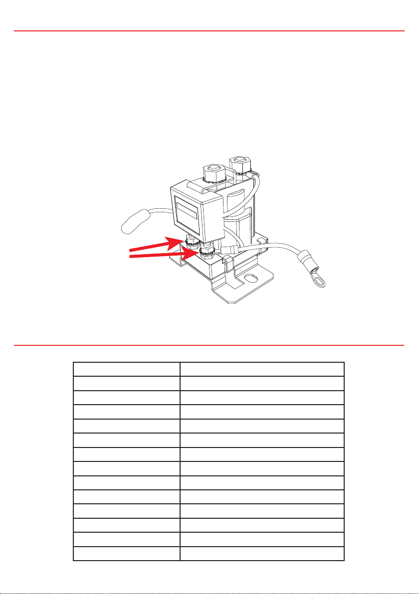
6. IMPORTANT! Do NOT make any connections to the control terminals found on the front of the unit. Ensure
that connections are not accidentally bridged between terminals whilst tightening. Connecting to the control
terminals on the front of the SBI may cause damage to the unit and/or equipment connected to it. Connecting
to the control terminals will void the warranty of the unit.
Do NOT
connect
to the control
terminals!
SPECIFICATIONS
System Voltage 12V Nominal
Turn ON Voltage 11.0V
Turn OFF Voltage 10.5V
Turn ON Delay 10 sec
Turn OFF Delay 2 sec
Max. Cont. Current 100 Amps
Max. Inrush Current 400 Amps
Standby Current < 5mA
Operating Current <0.1A
Dimensions 75 x 70 x 80mm
Weight 200g
Warranty 2 years
Standards CE, C-Tick, AS/NZS CISPR11:2004
Main Stud Torque 5-6.2 Nm
2
Page 4

THE SBI12-LLD
The SBI12-LLD is a microprocessor controlled Load Disconnect Isolator. The SBI12-LLD is designed
specifically for use in LiFePO4 battery applications as a system to protect the lithium battery from being
excessively discharged by auxiliary loads, enabling the auxiliary battery to remain above the level at
which internal protection circuitry would activate. Falling below this threshold would prevent many
chargers from recharging the battery.
Put simply, once the auxiliary battery has been overly discharged, the Load Disconnect Isolator will turn
off any connected loads. Similarly, if the battery climbs back above a suitable level, the Load Disconnect
Isolator will restore power to the connected loads.
RECOMMENDED FUSES & CABLING
Suitably sized Wire and fuses for the connected loads should be used. REDARC recommend using MIDI
fuses along with a quality fuse holder to match. The diagram below shows the construction of a MIDI
fuse installation (cables not included).
REDARC offer MIDI fuse kits containing the required fuses, fuse holders, crimps and nuts:
Part numbers
FK40 40A Fuse Kit
FK60 60A Fuse Kit
FK100 100A Fuse kit
3
Page 5

INSTALLATION INSTRUCTIONS
1. Mount the SBI12-LLD securely in a convenient location near the auxiliary battery bank. Do not
mount in direct engine heat.
2. Install in the order described below:
• Make sure the auxiliary battery negative is properly grounded to the vehicle chassis.
• Ground Connection. Connect the SBI12-LLD ground terminal to chassis ground. Remove any paint
to ensure a good ground connection. Note: A good ground will ensure correct switching voltage.
• Select correct Circuit Breaker/Fuse sizes and install at battery end of the positive cable
• LED Connections (optional). Connect a wire from the Blue wire of the SBI12-LLD to the positive
end of an indicator LED (15mA limited current draw) or LED/resistor combination.
• Override Feature (optional). Connect a wire from the Blue wire of the SBI12-LLD to one terminal
of a momentary push button switch. Connect the other terminal of the momentary push button
switch to the auxiliary battery supply. To manually operate the Load Disconnect Isolator (force
the loads to stay connected below the cutoff voltage), hold the momentary push button and the
Isolator will manually operate until the switch is released. Care should be taken not to excessively
discharge the Auxiliary battery.
• Checking the Operation: The SBI12-LLD should now be operational. Once the auxiliary battery
voltage rises to the ‘ON’ voltage the SBI12-LLD will activate, you will hear the solenoid click and
see the LED illuminate. Discharge the auxiliary battery. The SBI12-LLD will disconnect load from
the auxiliary battery once the voltage on the auxiliary battery drops to the ‘OFF’ Voltage; The
solenoid will make an audible click and the LED will go out. Note:
Over discharge risk. Ensure that the Turn OFF voltage is suitable for the specifications provided
by the battery manufacturer.
As per above, it is normal for the LED to stay ON whenever the auxiliary battery is in a condition
suitable for running loads.
The amount of time it takes for the battery voltage to drop low enough for the solenoid to turn off
will vary due to battery condition, age and state of charge. Refer to the table on page 2 for specific
voltage thresholds.
4
Page 6

STANDARD WIRING DIAGRAMS
• Ensure adequately sized cable is used.
• Ensure the auxiliary battery and loads
are properly grounded to a common
chassis earth point.
• Ensure the SBI12-LLD ground wire is
making good contact with the chassis
ground point.
• When using fuses make sure that the
fuse makes a good low resistance
connection.
• Fuse/Circuit Breaker ratings are
dependent on the type of installation
and the size of the loads.
Battery Charger
(LFPXXXX or BCDCXXXXD)
Fuse
Override
Wire
(BLUE)
Fuse
Battery
Terminal
Load
Fuse
Load
Terminal
Ground
Wire
(BLACK)
SBI12-LLD
Start
Battery
Refer to the Battery Charger’s user manual for
appropriate power cable size reccomendations
SBI with External LED
Override
Wire
LED
NO RESISTOR REQUIRED.
OPTION 1 OPTION 2 OPTION 3
Auxiliary
Battery
Standard Installation
SBI with Push Button
for Override and LED
Override
Wire
LED
Resistor values:
12V = 1kΩ or 24V = 2.2kΩ
5
5A
Fuse
Momentary
Pushbutton
SBI with Push Button
for Override
Override
Wire
Loads
5A
Fuse
Momentary
Pushbutton
Page 7

FAULT INDICATION
NOTE: The LED will be on when the SBI12-LLD is active (on).
Should a fault occur, the SBI12-LLD is set to notify the operator of the fault. The LED will flash
repeatedly with the following sequences:
CODE 1 2 Flashes Over-Voltage
CODE 2 3 Flashes Voltage Drop or Excessive Current Draw Fault
FAULT CODE 1: 2 Flashes (Over-Voltage Detection)
If the battery connected to the SBI12-LLD should rise above 15.5 Volts the Smart Start® will:
• Disconnect, to prevent the source of over-voltage reaching the load
• Flash the LED 2 times for 20 seconds, then reassess the fault condition, continuing until the fault is
cleared.
FAULT CODE 2: 3 Flashes (Voltage Drop / Excessive Current Draw)
If the SBI12-LLD detects a voltage drop across its contacts of greater than 1 Volt for more than ½
second then the unit will:
• Immediately protect itself and the load by disconnecting the load; and
• Flash the LED 3 times for 20 seconds, then reassess the presence of a fault, continuing until the
fault is cleared.
6
Page 8

FREQUENTLY ASKED QUESTIONS
Question: Is the unit protected against voltage spikes?
Answer: Yes, the SBI12-LLD incorporates a number of spike protection components specifically
designed to reduce the risk of damaging the unit. The SBI12-LLD is also designed to prevent any
spikes generated by the solenoid coil from affecting any vehicle equipment.
Question: What does the red LED indicate?
Answer: The red LED indicates the solenoid is activated and therefor the battery is supplying power to
the load. A flashing red LED during operation indicates a fault. See Fault Indication on page 6.
Question: Can the voltage limits and time delay settings be changed?
Answer: Yes! Both upper and lower voltage limits & on and off times can be changed. However, this
needs to be done at the time of manufacture and will incur a cost.
Question: We are experiencing repetitive switching of our SBI12-LLD. What could be causing this?
Answer: This can occur for one of two reasons. Firstly, switching an excessively large load which
would drop the battery to below its lower voltage limit and causing the SBI12-LLD to turn off. After
turning off the load, the battery would recover in voltage; If the battery voltage climbs higher than the
turn on threshold, the SBI12-LLD would turn the loads back on.
Secondly, voltage drop due to cable length (ie the SBI12-LLD being mounted too far from Auxiliary
battery) can cause the voltage at the battery terminal on the SBI12-LLD to be lower than at the auxiliary
battery, which can also cause the unit to switch off. Voltage seen by the SBI12-LLD will now rise again
until the SBI12-LLD switches back on. This switching will continue until the cause of voltage drop is
removed. On and Off Time delays are built into the product to avoid the solenoid contacts chattering in
this scenario.
Question: Does the internal LED illuminate when I use the external override switch?
Answer: Yes.
Question: Can I use the SBI12-LLD on a positive chassis vehicle?
Answer: Yes. Please contact REDARC for further information.
7
Page 9

TWO YEAR PRODUCT WARRANTY
Over the last three decades our company has established a reputation as the power conversion specialist.
A 100% Australian-owned company, we have met the needs of customers in transport and other industries through exciting, innovative thinking.
We believe in total customer satisfaction and practice this by offering our customers:
• Technical advice free of jargon and free of charge
• Prompt turnaround of orders throughout Australia and globally
• Friendly, personalised, professional service and product support
In the unlikely event that a technical issue arises with a Redarc product, customers are encouraged to initially contact the Redarc Technical Support Team on (08) 8322 4848
or power@redarc.com.au for prompt and efficient diagnosis and product support.
Our goods come with guarantees that cannot be excluded under the Australian Consumer Law. You are entitled to a replacement or refund for a major failure and compensation for
any other reasonably foreseeable loss or damage. You are also entitled to have the goods repaired or replaced if the goods fail to be of acceptable quality and the failure does not
amount to a major failure.
The benefits of this Warranty are in addition to other rights and remedies available at law in respect of the Products and shall not derogate from any applicable mandatory statutory
provisions or rights under the Australian Consumer Law.
Redarc Electronics Pty Ltd atf the Redarc Trust trading as Redarc Electronics (“Redarc”) offers a warranty in respect of its Products where the Products are purchased from an
authorised distributor or reseller of Redarc by a person (“Purchaser”), on the terms and conditions, and for the duration, outlined below in this document (“Warranty”).
1. In this Warranty, the term Products means:
1.1 all products manufactured or supplied by Redarc (excluding its solar products
which are covered by Redarc’s Solar Product Warranty); and
1.2 any component of or accessory for any product in clause 1.1 manufactured or
supplied by Redarc.
Offer and duration of product warranties
2. Redarc warrants that its Products will be free, under normal application, installation,
use and service conditions, from defects in materials and workmanship affecting
normal use, for 2 years from the date of purchase (Warranty Period).
3. Where a Product malfunctions or becomes inoperative during the Warranty Period,
due to a defect in materials or workmanship, as determined by Redarc, then subject
to further rights conferred by the Australian Consumer Law on the Purchaser,
Redarc will, in exercise of its sole discretion, either:
3.1 repair the defective Product;
3.2 replace the defective Product; or
3.3 provide a refund to the Purchaser for the purchase price paid for the defective
Product,
without charge to the Purchaser.
4. The warranty given by Redarc in clause 3 covers the reasonable costs of deliver y
and installation of any repaired or replaced Products or components of Products
to the Purchaser’s usual residential address notified to Redarc, together with the
reasonable costs of removal and return of any Products determined by Redarc to be
defective.
5. If the Purchaser incurs expenses of the nature referred to in clause 4 in the
context of making a claim pursuant to this Warranty that is accepted by Redarc,
the Purchaser will be entitled to claim for reimbursement of those expenses which
Redarc determines, in exercise of its sole discretion, to be reasonably incurred,
provided that the claim is notified to Redarc in writing at the postal address or email
address specified in clause 21 and includes:
5.1 details of the relevant expenses incurred by the Purchaser; and
5.2 proof of the relevant expenses having been incurred by the Purchaser.
Exclusions and limitations
6. This Warranty will not apply to, or include any defect, damage, fault, failure
or malfunction of a Product, which Redarc determines, in exercise of its sole
discretion, to be due to:
6.1 normal wear and tear or exposure to weather conditions over time;
6.2 accident, misuse, abuse, negligence, vandalism, alteration or modification;
6.3 non-observance of any of the instructions supplied by Redarc, including
instructions concerning installation, configuring, connecting, commissioning,
use or application of the Product, including without limitation choice of location;
6.4 failure to ensure proper maintenance of the Product strictly in accordance with
Redarc’s instructions or failure to ensure proper maintenance of any associated
equipment or machinery;
6.5 repairs to the Product that are not strictly in accordance with Redarc’s
instructions;
6.6 installation, repairs or maintenance of the Product by, or under the supervision
of, a person who is not a qualified auto electrician or technician, or if nongenuine or non-approved parts have been fitted;
6.7 faulty power supply, power failure, electrical spikes or surges, lightning, flood,
storm, hail, extreme heat, fire or other occurrence outside the control of
Redarc;
6.8 use other than for any reasonable purpose for which the Product was
manufactured;
6.9 any indirect or incidental damage of whatever nature outside the control of
Redarc.
7. Warranty claims in respect of a Product must be made in writing to Redarc at the
postal address or email address specified in clause 21 within the Warranty Period.
Such claims must include the following:
7.1 details of the alleged defect or fault and the circumstances surrounding the
defect or fault;
7.2 evidence of the claim, including photographs of the Product (where the subject
of the claim is capable of being photographed);
7.3 the serial number of the Product, specified on the label affixed to the Product;
and
7.4 proof of purchase documentation for the Product from an authorised distributor
or reseller of Redarc, which clearly shows the date and place of purchase.
The return of any Products without the prior written instructions of Redarc will not
be accepted by Redarc.
8. Without limiting any other clause in this Warranty, Redarc has the right to reject any
Warranty claim made by a Purchaser pursuant to this Warranty where:
8.1 the Purchaser does not notify Redarc in writing of a Warranty claim within the
Warranty Period;
8.2 the Purchaser does not notify Redarc in writing of a Warranty claim within 1
month of becoming aware of the relevant circumstances giving rise to the
claim, so that any further problems with the Product are minimised;
8.3 the serial number of the Product has been altered, removed or made illegible
without the written authority of Redarc;
8.4 the Purchaser is unable to provide proof of purchase documentation in
accordance with clause 7.4 or evidence that the Product was properly installed
and removed (if relevant), and that proper maintenance has been performed
on the Product, by, or under the supervision of, a qualified auto electrician or
technician, in accordance with the instructions of Redarc.
9. If the Product is found to be working satisfactorily on return to Redarc or upon
investigation by Redarc, the Purchaser must pay Redarc’s reasonable costs of
testing and investigating the Product in addition to shipping and transportation
charges. Where Redarc is in possession of the Product, the Product will be
returned to the Purchaser on receipt of the amount charged.
10. Any replaced Products or components of Products shall become the property of
Redarc.
11. Redarc may, in exercise of its sole discretion, deliver another type of Product or
component of a Product (different in size, colour, shape, weight, brand and/or
other specifications) in fulfilling its obligations under this Warranty, in the event
that Redarc has discontinued manufacturing or supplying the relevant Product or
component at the time of the Warranty claim, or where such Product or component
is superior to that originally purchased by the Purchaser.
Other conditions of Warranty
12. If the Purchaser acquired a Product for the purpose of resupply, then this Warranty
shall not apply to that Product.
13. In particular, the sale of a Product via an online auction, online store or other
internet website by a party that is not an authorised distributor or reseller of the
Product will be deemed to be a resupply within the meaning of the Australian
Consumer Law and will render this Warranty void, as Redarc has no control over the
storage, handling, quality or safety of Products sold by such persons.
14. A Purchaser shall only be entitled to the benefit of this Warranty after all amounts
owing in respect of the Product have been paid.
15. While Redarc warrants that the Products will be free from defects in materials and
workmanship in the circumstances set out in this Warranty, to the maximum extent
permitted by law Redarc does not warrant that the operation of the Products will be
uninterrupted or error-free.
16. To the maximum extent permitted by law, Redarc’s determination of the existence of
any defect and the cause of any defect will be conclusive.
17. Spare parts or materials for the Products are guaranteed to be available for a period
of at least 2 years after purchase of the Products.
18. The agents, officers and employees of any distributor or reseller of the Products and
of Redarc are not authorised to vary or extend the terms of this Warranty.
19. Redarc shall not be responsible or liable to the Customer or any third party in
connection with any non-performance or delay in performance of any terms and
conditions of this Warranty, due to acts of God, war, riots, strikes, warlike conditions,
plague or other epidemic, fire, flood, blizzard, hurricane, changes of public policies,
terrorism and other events which are beyond the control of Redarc. In such
circumstances, Redarc may suspend performance of this Warranty without liability
for the period of the delay reasonably attributable to such causes.
20. If a clause or part of a clause in this Warranty can be read in a way that makes it
illegal, unenforceable or invalid, but can also be read in a way that makes it legal,
enforceable and valid, it must be read in the latter way. If any clause or part of
a clause in this Warranty is illegal, unenforceable or invalid, that clause or part is
to be treated as removed from this Warranty, but the rest of this Warranty is not
affected.
Redarc’s contact details
21. Redarc’s contact details for the sending of Warranty claims under this Warranty are:
Redarc Electronics Pty Ltd
23 Brodie Road (North), Lonsdale SA 5160
Email: power@redarc.com.au
Telephone: +61 8 8322 4848
8
Page 10

Free technical assistance!
please contact
REDARC Electronics
23 Brodie Road North, Lonsdale SA
(08) 8322 4848
power@redarc.com.au
www.redarc.com.au
Mailing Address
PO Box 469
Morphett Vale
South Australia 5162
Copyright © 2017 REDARC Electronics Pty Ltd. All rights reserved.
WARSBI12LLD - REV1
www.redarc.com.au
 Loading...