

Page 1
12V Dual Battery Isolator & Wire Kit
SBI12KIT
FUNCTION
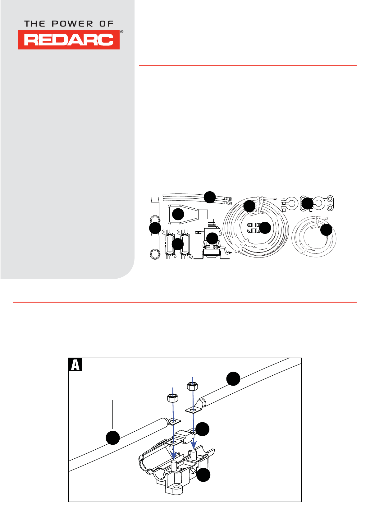
KIT CONTENTS
1. 200mm Battery Positive
cable (red)
2. 1800mm Battery Positive
cable (red)
3. Fuses (60A)
4. Fuse holders (incl.
mounting nuts)
5. Battery Terminals
6. Isolator Terminal
protectors
7. SBI12 Battery Isolator
8. 750mm Auxiliary battery
ground cable (black)
9. Battery terminal protector
for Auxiliary Battery
Positive Terminal.
x2
x2
x2
x2
x2
x2
x1
x1
x1
The Smart Start® Dual Battery Isolator & Wire Kit (part
number SBI12KIT) comes with everything required to install
your Smart Start
®
Start
itself.
®
Dual Battery Isolator, including the Smart
Perfectly suited to the Do-It-Yourself installer, the SBI12KIT
requires no crimping or soldering, it’s just plug and play.
The SBI12KIT features high quality MTA 60 Amp fuses and
fuse holders with the corresponding ring terminals already
attached to the wires.
1
2
5
9
6
3
8
7
4
®
Please refer to the Smart Start
SBI Manual for more info.
WIRING INSTRUCTIONS
1 * REMOVE MAIN BATTERY EARTH *
2 Place fuses in fuse holders and attach red cables as shown in diagram A.
Numbers refer to
the contents list
2
3
1
4
Copyright © 2012 Redarc Electronics Pty. Ltd. All rights reserved.
Page 2
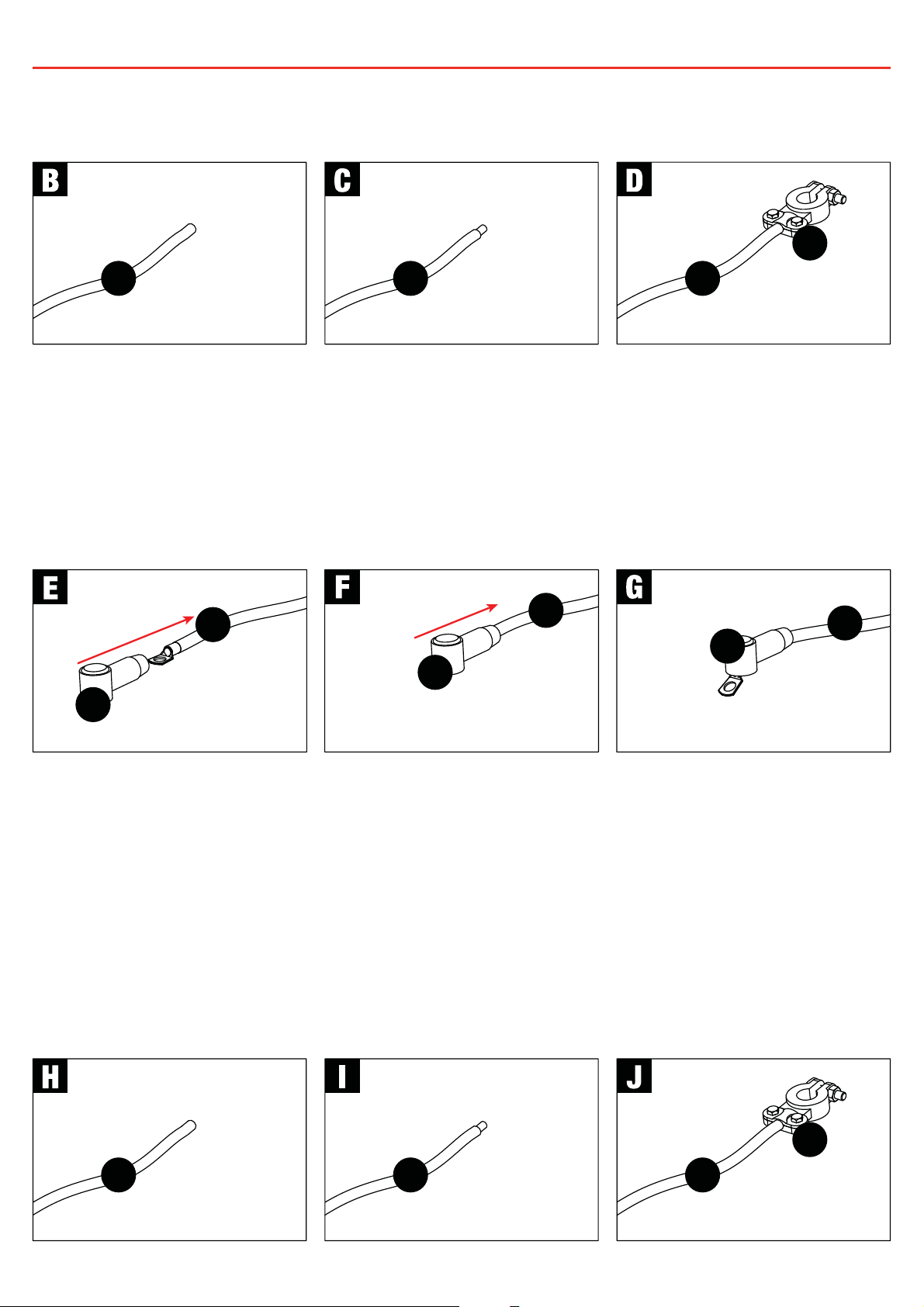
WIRING INSTRUCTIONS
3 Connect a Battery Positive cable (Cable 1) to one of the battery terminals as shown in
diagrams B, C & D. This terminal will attach to your Auxiliary Battery positive terminal.
Strip wire
1 1
4 Remove the Start Battery positive terminal from your Start Battery. Connect the other
Battery Positive cable (Cable 1) into the existing Battery Terminal from your Start
Battery. Reconnect the existing Battery Terminal to your Start Battery positive terminal.
5 Insert the crimped ends of the Battery Positive cables into the isolator terminal
protectors provided as per diagrams E, F & G.
1
Insert wire
into battery
terminal
2
5
2
2
6
6
6
6 Mount the SBI unit in a convenient location, as shown in diagram K. Redarc
recommends connecting the SBI as close as possible to the start battery.
7 Connect the SBI ground wire to chassis earth as shown in diagram L. Ensure a good
connection is made and any paint has been removed from the mounting location.
8 Connect the Ground terminal of the Auxiliary battery to chassis earth, using the 750mm
Auxiliary Battery ground cable and the other battery terminal provided as per diagrams
H, I & J.
5
Strip wire
8 8
8
Insert wire
into battery
terminal
Page 3

WIRING INSTRUCTIONS
* MOUNT THE SBI12 *
Nuts, Bolts and
Mounting Plate
not provided.
7
* ATTACH THE EARTH WIRE *
Ensure ground
point makes a
good electrical
connection to
the negative
terminal of both
7
batteries.
9 Wire the SBI12 as shown in diagrams M,N & O. Ensure that all connections are tight
and that the provided spring washers are used.
6
2
7
6
2
6
6
6
6
7
10 * RECONNECT MAIN BATTERY EARTH *
Page 4

TWO YEAR PRODUCT WARRANTY
Over the last three decades our company has established a reputation as the power conversion specialist.
A 100% Australian-owned company, we have met the needs of customers in transport and other industries through exciting, innovative thinking.
We believe in total customer satisfaction and practice this by offering our customers:
• Technical advice free of jargon and free of charge
• Prompt turnaround of orders throughout Australia and globally
• Friendly, personalised, professional service and product support
In the unlikely event that a technical issue arises with a Redarc product, customers are encouraged to initially contact the Redarc Technical Support Team on (08) 8322 4848
or
power@redarc.com.au
for prompt and effi cient diagnosis and product support.
Our goods come with guarantees that cannot be excluded under the Australian Consumer Law. You are entitled to a replacement or refund for a major failure and compensation for
any other reasonably foreseeable loss or damage. You are also entitled to have the goods repaired or replaced if the goods fail to be of acceptable quality and the failure does not
amount to a major failure.
The benefi ts of this Warranty are in addition to other rights and remedies available at law in respect of the Products and shall not derogate from any applicable mandatory statutory
provisions or rights under the Australian Consumer Law.
Redarc Electronics Pty Ltd atf the Redarc Trust trading as Redarc Electronics (“
Redarc
”) offers a warranty in respect of its Products where the Products are purchased from an
authorised distributor or reseller of Redarc by a person (“
Purchaser
”), on the terms and conditions, and for the duration, outlined below in this document (“
Warranty
”).
Over the last three decades our company has established a reputation as the power conversion specialist.
A 100% Australian-owned company, we have met the needs of customers in transport and other industries through exciting, innovative thinking.
We believe in total customer satisfaction and practice this by offering our customers:
• Technical advice free of jargon and free of charge
• Prompt turnaround of orders throughout Australia and globally
• Friendly, personalised, professional service and product support
In the unlikely event that a technical issue arises with a Redarc product, customers are encouraged to initially contact the Redarc Technical Support Team on (08) 8322 4848
or
power@redarc.com.au
Our goods come with guarantees that cannot be excluded under the Australian Consumer Law. You are entitled to a replacement or refund for a major failure and compensation for
any other reasonably foreseeable loss or damage. You are also entitled to have the goods repaired or replaced if the goods fail to be of acceptable quality and the failure does not
amount to a major failure.
The benefi ts of this Warranty are in addition to other rights and remedies available at law in respect of the Products and shall not derogate from any applicable mandatory statutory
provisions or rights under the Australian Consumer Law.
Redarc Electronics Pty Ltd atf the Redarc Trust trading as Redarc Electronics (“
authorised distributor or reseller of Redarc by a person (“
1. In this Warranty, the term Products means:
1.1 all products manufactured or supplied by Redarc (excluding its solar products
which are covered by Redarc’s Solar Product Warranty); and
1.2 any component of or accessory for any product in clause 1.1 manufactured or
supplied by Redarc.
Offer and duration of product warranties
2. Redarc warrants that its Products will be free, under normal application, installation,
use and service conditions, from defects in materials and workmanship affecting
normal use, for 2 years from the date of purchase (Warranty Period).
3. Where a Product malfunctions or becomes inoperative during the Warranty Period,
due to a defect in materials or workmanship, as determined by Redarc, then subject
to further rights conferred by the Australian Consumer Law on the Purchaser,
Redarc will, in exercise of its sole discretion, either:
3.1 repair the defective Product;
3.2 replace the defective Product; or
3.3 provide a refund to the Purchaser for the purchase price paid for the defective
Product,
without charge to the Purchaser.
4. The warranty given by Redarc in clause 3 covers the reasonable costs of delivery
and installation of any repaired or replaced Products or components of Products
to the Purchaser’s usual residential address notifi ed to Redarc, together with the
reasonable costs of removal and return of any Products determined by Redarc to be
defective.
5. If the Purchaser incurs expenses of the nature referred to in clause 4 in the
context of making a claim pursuant to this Warranty that is accepted by Redarc,
the Purchaser will be entitled to claim for reimbursement of those expenses which
Redarc determines, in exercise of its sole discretion, to be reasonably incurred,
provided that the claim is notifi ed to Redarc in writing at the postal address or email
address specifi ed in clause 21 and includes:
5.1 details of the relevant expenses incurred by the Purchaser; and
5.2 proof of the relevant expenses having been incurred by the Purchaser.
Exclusions and limitations
6. This Warranty will not apply to, or include any defect, damage, fault, failure
or malfunction of a Product, which Redarc determines, in exercise of its sole
discretion, to be due to:
6.1 normal wear and tear or exposure to weather conditions over time;
6.2 accident, misuse, abuse, negligence, vandalism, alteration or modifi cation;
6.3 non-observance of any of the instructions supplied by Redarc, including
instructions concerning installation, confi guring, connecting, commissioning,
use or application of the Product, including without limitation choice of location;
6.4 failure to ensure proper maintenance of the Product strictly in accordance with
Redarc’s instructions or failure to ensure proper maintenance of any associated
equipment or machinery;
6.5 repairs to the Product that are not strictly in accordance with Redarc’s
instructions;
6.6 installation, repairs or maintenance of the Product by, or under the supervision
of, a person who is not a qualifi ed auto electrician or technician, or if nongenuine or non-approved parts have been fi tted;
6.7 faulty power supply, power failure, electrical spikes or surges, lightning, fl ood,
storm, hail, extreme heat, fi re or other occurrence outside the control of
Redarc;
6.8 use other than for any reasonable purpose for which the Product was
manufactured;
6.9 any indirect or incidental damage of whatever nature outside the control of
Redarc.
7. Warranty claims in respect of a Product must be made in writing to Redarc at the
postal address or email address specifi ed in clause 21 within the Warranty Period.
Such claims must include the following:
7.1 details of the alleged defect or fault and the circumstances surrounding the
defect or fault;
7.2 evidence of the claim, including photographs of the Product (where the subject
of the claim is capable of being photographed);
7.3 the serial number of the Product, specifi ed on the label affi xed to the Product;
and
7.4 proof of purchase documentation for the Product from an authorised distributor
or reseller of Redarc, which clearly shows the date and place of purchase.
The return of any Products without the prior written instructions of Redarc will not
be accepted by Redarc.
WARSBI12KIT - REV2
for prompt and effi cient diagnosis and product support.
Redarc
Purchaser
”), on the terms and conditions, and for the duration, outlined below in this document (“
”) offers a warranty in respect of its Products where the Products are purchased from an
8. Without limiting any other clause in this Warranty, Redarc has the right to reject any
Warranty claim made by a Purchaser pursuant to this Warranty where:
8.1 the Purchaser does not notify Redarc in writing of a Warranty claim within the
Warranty Period;
8.2 the Purchaser does not notify Redarc in writing of a Warranty claim within 1
month of becoming aware of the relevant circumstances giving rise to the
claim, so that any further problems with the Product are minimised;
8.3 the serial number of the Product has been altered, removed or made illegible
without the written authority of Redarc;
8.4 the Purchaser is unable to provide proof of purchase documentation in
accordance with clause 7.4 or evidence that the Product was properly installed
and removed (if relevant), and that proper maintenance has been performed
on the Product, by, or under the supervision of, a qualifi ed auto electrician or
technician, in accordance with the instructions of Redarc.
9. If the Product is found to be working satisfactorily on return to Redarc or upon
investigation by Redarc, the Purchaser must pay Redarc’s reasonable costs of
testing and investigating the Product in addition to shipping and transportation
charges. Where Redarc is in possession of the Product, the Product will be
returned to the Purchaser on receipt of the amount charged.
10. Any replaced Products or components of Products shall become the property of
Redarc.
11. Redarc may, in exercise of its sole discretion, deliver another type of Product or
component of a Product (different in size, colour, shape, weight, brand and/or
other specifi cations) in fulfi lling its obligations under this Warranty, in the event
that Redarc has discontinued manufacturing or supplying the relevant Product or
component at the time of the Warranty claim, or where such Product or component
is superior to that originally purchased by the Purchaser.
Other conditions of Warranty
12. If the Purchaser acquired a Product for the purpose of resupply, then this Warranty
shall not apply to that Product.
13. In particular, the sale of a Product via an online auction, online store or other
internet website by a party that is not an authorised distributor or reseller of the
Product will be deemed to be a resupply within the meaning of the Australian
Consumer Law and will render this Warranty void, as Redarc has no control over the
storage, handling, quality or safety of Products sold by such persons.
14. A Purchaser shall only be entitled to the benefi t of this Warranty after all amounts
owing in respect of the Product have been paid.
15. While Redarc warrants that the Products will be free from defects in materials and
workmanship in the circumstances set out in this Warranty, to the maximum extent
permitted by law Redarc does not warrant that the operation of the Products will be
uninterrupted or error-free.
16. To the maximum extent permitted by law, Redarc’s determination of the existence of
any defect and the cause of any defect will be conclusive.
17. Spare parts or materials for the Products are guaranteed to be available for a period
of at least 2 years after purchase of the Products.
18. The agents, offi cers and employees of any distributor or reseller of the Products and
of Redarc are not authorised to vary or extend the terms of this Warranty.
19. Redarc shall not be responsible or liable to the Customer or any third party in
connection with any non-performance or delay in performance of any terms and
conditions of this Warranty, due to acts of God, war, riots, strikes, warlike conditions,
plague or other epidemic, fi re, fl ood, blizzard, hurricane, changes of public policies,
terrorism and other events which are beyond the control of Redarc. In such
circumstances, Redarc may suspend performance of this Warranty without liability
for the period of the delay reasonably attributable to such causes.
20. If a clause or part of a clause in this Warranty can be read in a way that makes it
illegal, unenforceable or invalid, but can also be read in a way that makes it legal,
enforceable and valid, it must be read in the latter way. If any clause or part of
a clause in this Warranty is illegal, unenforceable or invalid, that clause or part is
to be treated as removed from this Warranty, but the rest of this Warranty is not
affected.
Redarc’s contact details
21. Redarc’s contact details for the sending of Warranty claims under this Warranty are:
Warranty
”).
Redarc Electronics Pty Ltd
23 Brodie Road (North), Lonsdale SA 5160
Email: power@redarc.com.au
Telephone: +61 8 8322 4848
SAL.FOR.Instruction Manual.SBI12KIT – DOC515 – Version 2
www.redarc.com.au
 Loading...