

Page 1

Total Vehicle
Management System
TVMS1280
Page 2

THE REDVISION TOTAL VEHICLE MANAGEMENT SYSTEM
The RedVision Total Vehicle Management System (TVMS) sets an unprecedented level
of automation in the recreational vehicle industry by allowing users to control multiple
on-board devices with one easy to use system.
RedVision acts as a central hub that connects devices and displays vital information
for the vehicle and its on-board accessories. RedVision allows the user to turn lights,
inverters, water pumps and other loads such as televisions, electric steps and fridges on
or off, while displaying water levels, temperature, energy (battery power) consumption
and storage*.
WARNINGS & SAFETY INSTRUCTIONS
1. SAVE THESE INSTRUCTIONS - THIS MANUAL CONTAINS IMPORTANT SAFETY INSTRUCTIONS FOR THE
REDVISION TOTAL VEHICLE MANAGEMENT SYSTEM (TVMS).
2. DO NOT OPERATE THE SYSTEM UNLESS YOU HAVE READ AND UNDERSTOOD THIS MANUAL AND THE
SYSTEM IS INSTALLED AS PER THESE INSTALLATION INSTRUCTIONS. REDARC RECOMMENDS THAT THE
SYSTEM BE INSTALLED BY A SUITABLY QUALIFIED PERSON.
1. Risk of explosive gases: Working in the vicinity of a Lead-Acid battery is dangerous. Batteries generate explosive
gases during normal operation. For this reason, it is of utmost importance that you follow the instructions each
time you use the system.
2. The system should not be used by persons (including children) with reduced physical, sensory or mental
capabilities, or lack of experience and knowledge, unless they are supervised or have been instructed on how
to use the appliance by a person responsible for their safety. Children should be supervised to ensure that they
do not play with the system.
3. Do NOT alter or disassemble the system under any circumstances. All services or repairs must be returned to
REDARC for repair. Incorrect handling or reassembly may result in a risk of electric shock or fi re and may void
the unit warranty.
4. Use of an attachment not recommended or sold by REDARC may result in a risk of fi re, electric shock, or injury
to persons.
5. Cable and fuse sizes are specifi ed by various codes and standards which depend on the type of vehicle the
system is installed into. Selecting the wrong cable or fuse size could result in harm to the installer or user and/
or damage to the TVMS or other equipment installed in the system. The installer is responsible for ensuring that
the correct cable and fuse sizes are used when installing this system.
6. Be extra cautious so as to reduce the risk of dropping a metal tool onto a vehicle battery. Doing so might cause
the battery to spark or might short-circuit the battery or other electrical parts that may cause an explosion.
7. Remove personal metal items such as rings, bracelets, necklaces, and watches when working with a lead-acid
battery. A lead-acid battery can produce a short-circuit current high enough to weld a ring or the like to metal,
causing a severe burn.
SAL.FOR.Instruction Manual.TVMS1280-UM – Version 5
1
*Energy (battery power) consumption and storage
available when used with a REDARC BMS.
Page 3

8. NEVER SMOKE OR ALLOW A SPARK OR FLAME NEAR A BATTERY AS THESE MAY CAUSE THE BATTERY
TO EXPLODE. TO REDUCE THE RISK OF A SPARK NEAR A BATTERY WHEN CONNECTING THE BATTERY
INSTALLED IN A VEHICLE TO THE TVMS, ALWAYS DO THE FOLLOWING:
Wire the Output Connector before connecting it to the Distribution Box. During connection of the unit, the
Battery Output (positive) must be connected fi rst, followed by the Ground (chassis) terminal. The chassis
connection should be made away from the battery and fuel lines. Once all connections are wired to the
Output Connector, plug the connector into the Distribution Box.
9. Do not use this product to control safety critical devices or those that could cause harm if operated remotely
(for example fume exhaust fans or lifters).
10. Ensure that the Display is not mounted in vehicle head-impact zones. Doing so may result in injury to the driver
and/or passenger in the event of an accident.
11. Ensure the Display is not mounted where it may distract the driver of the vehicle. Distracting the driver may
result in an accident.
12. Risk of damage to the system. Do NOT connect a load negative (-) to the chassis AND to the applicable negative
(-) output channel as this may cause damage to the Distribution Box under some circumstances. Connect to the
applicable negative (-) output channel OR a suitable chassis grounding point to avoid damage.
13. Risk of damage to the system. Do NOT connect to the ‘TRC’ socket at the front (240V end) of the inverter as
this will cause damage to the RedVision Distribution Box. Connect to the ‘REMOTE’ socket to avoid damage.
1. Do NOT connect computers or IT equipment to the RJ45 ports on the RedVision Distribution Box or Display.
Damage may occur.
2. It is recommended to leave the Display connected at all times to the base unit.
3. The Distribution Box may be mounted in any orientation but must be mounted onto a fl at, solid surface using
4 x M6 screws or bolts. Failure to adequately mount the unit, such as using adhesives to mount the unit will
result in unreliable operation of the Distribution Box.
4. It is the installer’s responsibility to ensure their installation complies with any applicable legal and regulatory
requirements. Within Australia, installers may wish to consult AS/NZS 3001 as one potentially relevant standard.
5. Ensure that the channel and master override dip-switches are turned off after use to prevent accidental
operation of the channel / fl attening of either the Starter or Auxiliary battery.
6. The RedVision App and its interactions with RedVision has not been tested on all smartphones available on
the market so is not guaranteed to work on all devices. However, the app should work on most phones with
®
Bluetooth
4.0 (or later) running IOS 11. 1 (or later) or Android 7.0 (or later).
7. The Confi gurator App. allows modifi cation to the core system functionality of your RedVision system, only use
this App if you have read and fully understand all instructions in this manual.
2
Page 4

CONTENTS
Table of Contents
Warnings & Safety Instructions 1
Features and Benefi ts
1. Introduction
1.1 Kit Contents
1.2 Specifi cations
1.3 Compatible Devices
1.4 Dimensions
2. Installation Guide
2.1 System Layout
2.2 Mounting Instructions
2.3 DC Cable Size Requirements
2.4 Digital I/Os
2.5 Fuses
2.6 Battery & Charger Connection
2.7 Temperature Sensors
4
5
5
6
6
7
9
9
10
14
15
16
18
20
2.8 R-Bus Connection
2.9 Water Level Sensors
2.10 Optional Inverter Connection
3. System Confi guration
3.1 RedVision Confi gurator App.
3.2 Confi gure Charger
3.3 Confi gure Battery Sensor
3.4 Confi gure Distribution Box - Load Disconnect Settings
3.5 Confi gure Distribution Box - Channels
3.6 Confi gure Display - Soft Keys
3.7 Confi gure Display - Home Screen
3.8 Confi gure Display - Status Screen
3.9 Confi gure Display - Temperature Units
4. User Guide
21
23
24
25
25
26
26
27
28
31
32
33
34
35
1.1 The Display
3.2 Fault Display
3.3 The RedVision App
5. Display Drill Template
6. Two Year Product Warranty
35
44
45
48
50
3
Page 5

FEATURES AND BENEFITS
Why use RedVision?
• Integration service provided to OEM’s to make the most of the product and our
manufacturing experience
• Confi gurable software to meet the specifi cation of different vehicles
• Differentiation against lower cost, lower tech, competitors
• REDARC reliability, warranty, and after sales service
Customer Benefi ts of RedVision
• Modern, user friendly interface
• Wireless information and control from mobile device
• Easy to understand simple system layout
• Feature expandability after sales
• REDARC quality
OEM Benefi ts of RedVision
• Feature expandability for vehicle customisation to customer order
• Easily up sell value add components such as inverters
• Decreased installation time and complexity
• Reduced weight and area of components
• Improved service and support
• Packaged pricing and delivery
• Decreased production time
Features
• Read up to two temperatures
• Read up to six water tanks
• View and control inverter*
• View battery charging, load, and condition information*
1
2
• Switch up to 10 outputs
• Fuse up to 10 circuits plus charger circuit
• Automate output functionality
• Works with a range of REDARC charging systems
*1 When used in conjunction with a REDARC RS Series Inverter.
4
2
*
When used in conjunction with a REDARC Manager.
Page 6

1 INTRODUCTION
1.1 Kit Contents
Distribution Box (TVMS1280-DB):
Qty Part
1 Distribution box
1 Fuse cover panel (fi tted)
1 Fuse puller tool (fi tted)
1 80A midi fuse
1 Midi fuse holder
2 50A midi fuses (fi tted)
4 Crimp terminals for fuse holder
1 0.5m R-Bus Cable
Display (DISP4300):
Qty Part
1 3m Inverter Remote Cable
1 R-Bus Terminator
2 Temperature Sensors
6 Power cable mating connectors
1 Digital I/O mating connector
1 4.3” Display
1 Optional Mounting Spacer
1 Display Fascia
1 R-Bus Terminator
1 5m R-Bus Cable
5
Page 7

1 INTRODUCTION
1.2 Specifi cations
Compliance
Safety IEC60335
General Specifi cations
Operating Temperature -20°C to 60°C -20°C to 75°C
Storage Temperature -40°C to 85°C -40°C to 85°C
Dimensions (see pages 7-8) 385 x 138 x 58mm 178 x 108 x 26mm
Environemntal Protection IP30 Splash Resistant
Product Weight 2.0kg 0.3kg
Warranty 2 years
Electrical Specifi cations
Distribution Box Display
System Voltage 12V
Maximum Charger Current 40A
Maximum Battery Current 80A
No. Switched Circuits 5 x 10A Max, 5 x 30A Max
1.3 Compatible Devices
Type REDARC Part
BCDC1220
BCDC1220-IGN
Chargers
BCDC1225D
BCDC1240D
Battery Management
Systems
BMS1215S3
BMS1230S2
Number
Device
Connection Wire
N/A Section 2.6
CAN/R-BUS Section 2.8
Relevant section of
this manual
Inverters
R-12-350RS
R-12-700RS
R-12-1000RS
R-12-1500RS
R-12-2000RS
R-12-3000RS
REMOTE
Section 2.10
(NOT ‘TRC’)
6
Page 8
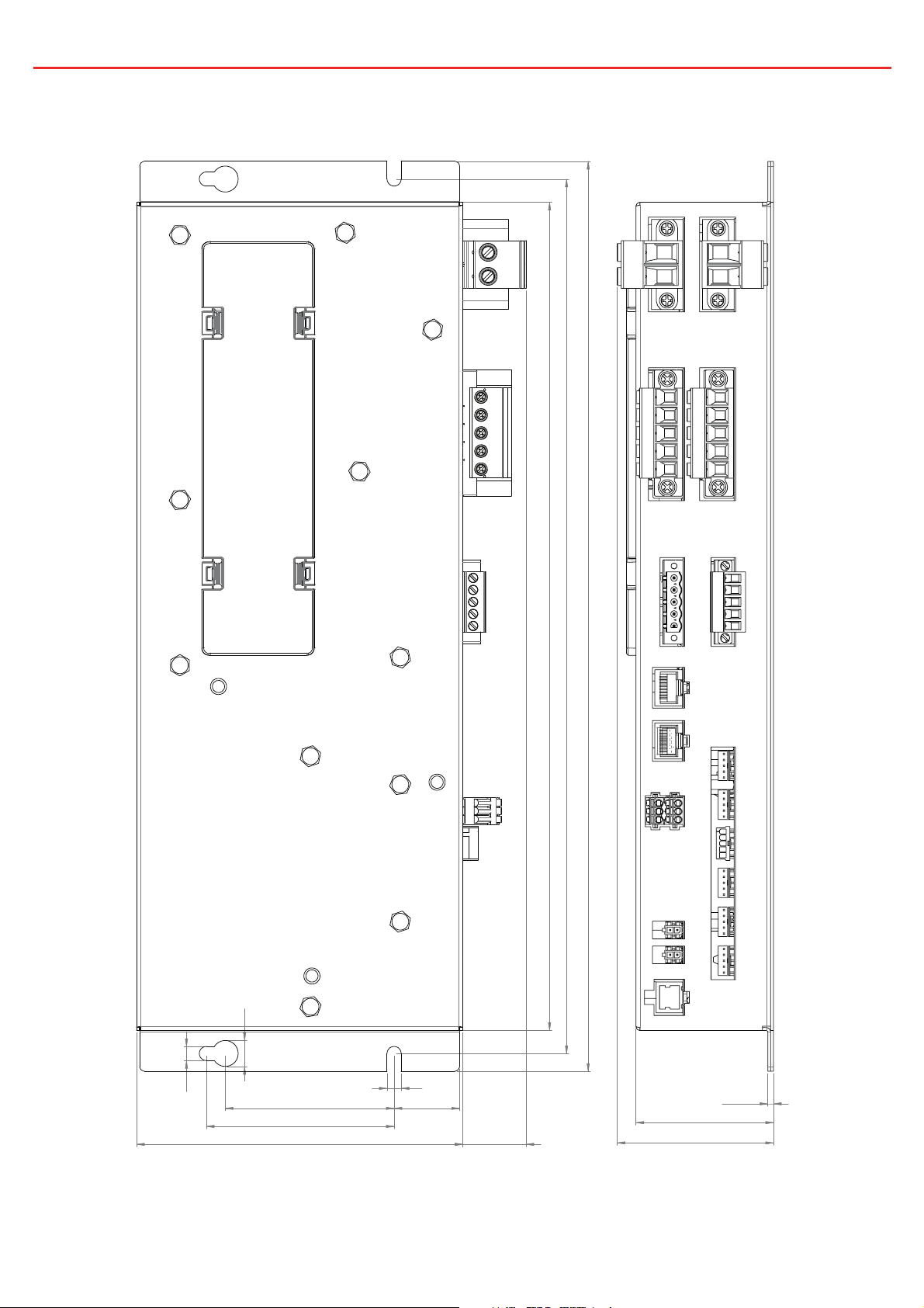
1 INTRODUCTION
1.4 Dimensions
Ø11mm
370mm
350mm
385mm
Ø6mm
Ø6mm
71.5mm
80mm
138mm
28mm
27mm
Figure 1.4.1 - Distribution Box Dimensions
7
2.5mm
58mm
66mm
Page 9
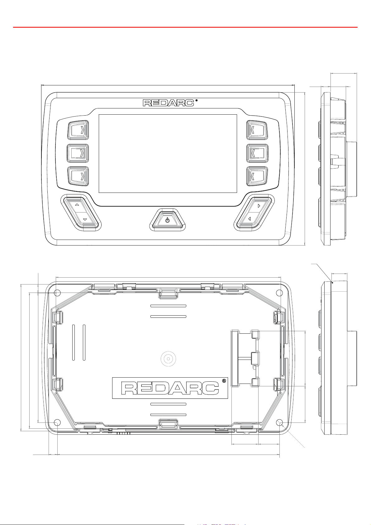
1 INTRODUCTION
18.5mm
178mm
7mm
107.5mm
11mm
96mm
103mm
6mm
91mm 6mm
158mm
156mm
Optional Spacer
11mm
25.5mm 39mm
Ø4.5mm X 4
19mm 15mm
Figure 1.4.2 - Display Dimensions
8
Page 10
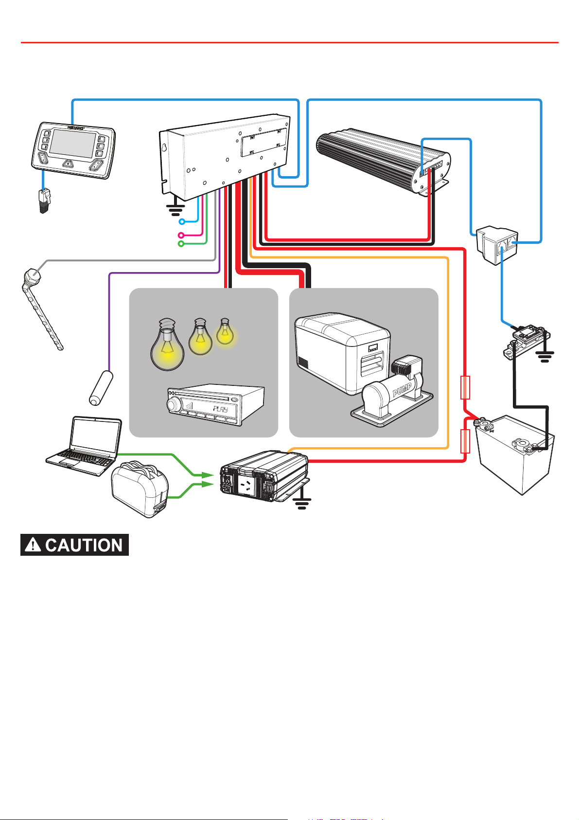
2 INSTALLATION GUIDE
2.1 System Layout
Distribution Box
Display
Terminating Resistor
BMS
Water
Level Sensors
Temperature
Sensors
To Ignition
To Alternate Trigger Signals
T-Piece
Small Loads Large Loads
Battery
Sensor
FuseFuse
Inverter
Auxiliary Battery
Do not use this product to control safety critical devices or those that could cause harm
if operated remotely (for example fume exhaust fans or lifters).
9
Page 11
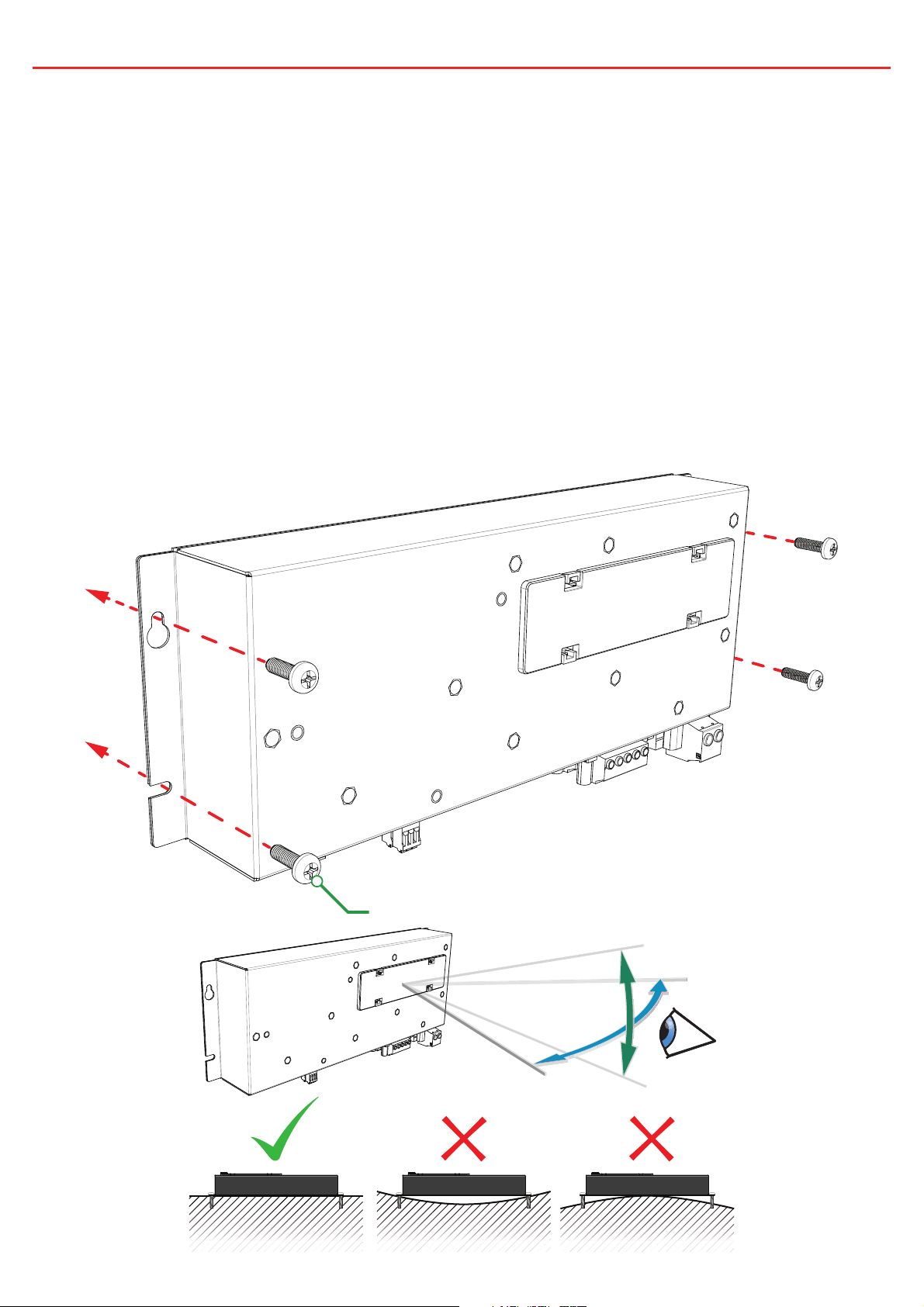
2 INSTALLATION GUIDE
2.2 Mounting Instructions
The Distribution Box should be mounted as close as possible to the auxiliary
battery(s) and Battery Charger to avoid voltage drop.
2.2.1 Mounting the Distribution Box
The Distribution Box may be mounted in any orientation but must be mounted
onto a fl at, solid surface using 4 x M6 screws or bolts. Failure to adequately
mount the unit, such as using adhesives to mount the unit may result in unreliable
operation of the Distribution Box. Ensure clear access to the fuse panel to ensure
service of fuses and override of channels can be performed.
4 x M6
±15°
±30°
10
Page 12
2 INSTALLATION GUIDE
2.2.2 Mounting the Display
The Display should be mounted inside the vehicle (Refer to page 48 for a 1:1
cutout template). It is however acceptable to mount the Display in any convenient
location, as long as it is protected from harsh environments such as being exposed
to rain or severe amounts of dust or full-time direct sunlight.
Spacer
(optional)
Display
4 x M4 or 8G
Bezel
4.2mm Max
8mm Max
Max
3.3mm
Ensure that the Display is not mounted in vehicle head-impact zones. Doing so may result
in injury to the driver and/or passenger in the event of an accident.
Ensure the Display is not mounted where it may distract the driver of the vehicle.
Distracting the driver may result in an accident.
11
Page 13
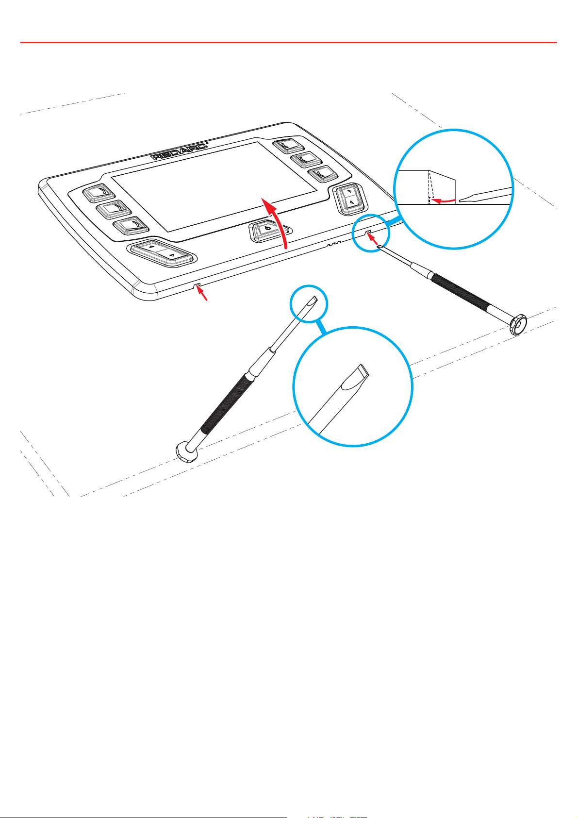
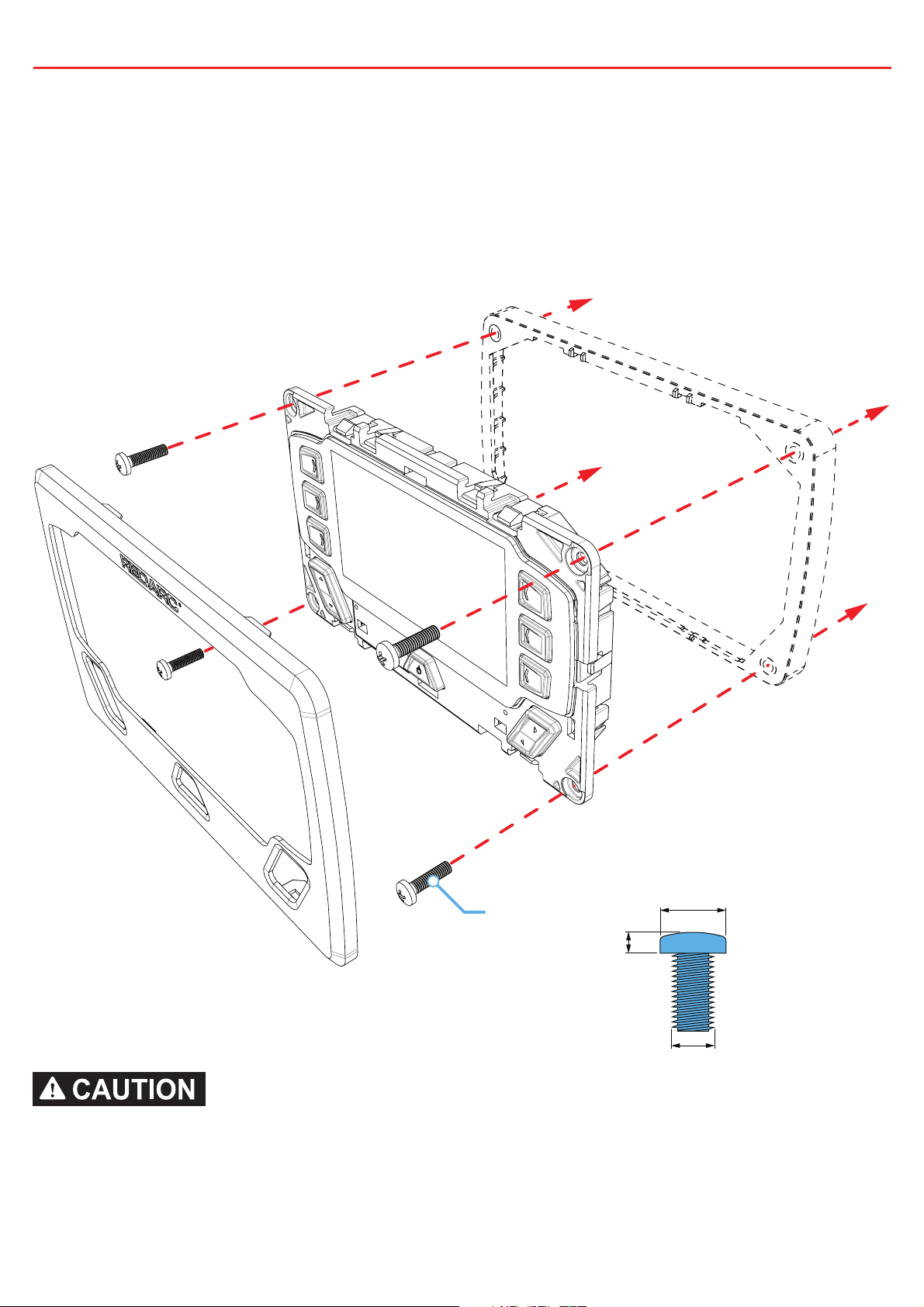
2 INSTALLATION GUIDE
2.2.3 Removing the Display Fascia
12
Page 14
2 INSTALLATION GUIDE
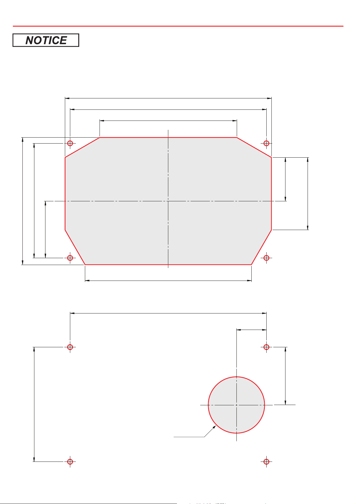
Refer to page 48 for a 1:1 cutout template
2.2.4 Flush Mount Drill/Cut Dimensions
164
156
109
NOT TO SCALE
Refer to page 48 for a 1:1 cutout template
45
91
101
132
2.2.5 Surface Mount Drill/Cut Dimensions
156
35
58
24
91
46
NOT TO SCALE
Refer to page 48 for a 1:1 cutout template
Ø45mm
13
Page 15

2 INSTALLATION GUIDE
2.3 DC Cable Size Requirements
2.3.1 Input Wire size
REDARC recommends the installer use cabling between 8-4B&S automotive.
Refer to the table below for further information.
Max Cable
Connection Terminal Size
Charger Output &
16 mm² 4B&S 8B&S 6B&S
Ground
Auxiliary Battery
16 mm² 4B&S 6B&S 4B&S
Positive & Ground
2.3.2 Output Wire Diameter Selection
REDARC recommends the installer use suitably rated cable and fuses for the load
connected. Refer to the table below for the 10 and 30 amp connector terminal
sizes and maximum cable sizes.
Connection Terminal Size Max Cable Size
Size
Cable length
<3M
Cable Length
>3M
10A Circuits 2.5 mm² 6 mm Auto
30A Circuits 6.0 mm² 8B&S
14
Page 16
2 INSTALLATION GUIDE
2.4 Digital I/Os
1
Digital Inputs
2
3
1
2
3
Start Battery Positive
Start Battery Negative
The Distribution Box incorporates 3 digital inputs.
1
The digital inputs,
2
,
and 3, can be confi gured to switch Distribution Box output
loads on/off when triggered (for example, to turn off all loads except a fridge when the
vehicle ignition is on).
The Start Battery Positive (
) and Start Battery Negative ( ) inputs can be used
to monitor and display a voltage from an external source (for example, to display the
vehicle’s starter battery voltage).
15
Page 17

2 INSTALLATION GUIDE
e
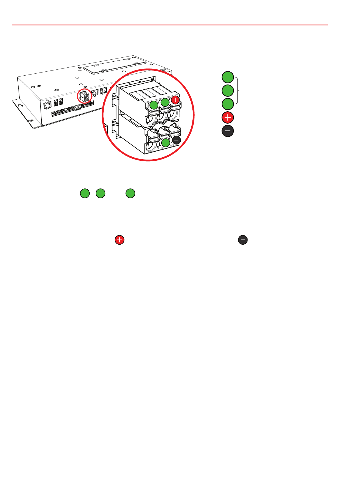
2.5 Fuses
Spare Charger Fuse
Override Switches
10A Max
Circuit Fuses
30A Max Circuit Fuses
Spare Fuses
50A Charger Fus
2.5.1 Fuse Locations
The Distribution Box load output channels are protected by standard blade fuses located
in the fuse panel:
Qty Part Type
5 10A Max Loads Blade Fuses Not Supplied
5 30 Max Loads Blade Fuses Not Supplied
4 Spare Fuse Holders Blade Fuses Not Supplied
1 50A Charger Fuse MIDI Supplied
1 Spare Fuse Holder MIDI Supplied
Additionally a 1 x 80A Battery Fuse and Fuse Holder are supplied.
To protect the Distribution Box from harsh startup currents, inductive type loads (e.g. large
fridges, pumps, motors) should be connected through the 30A Max circuits.
2.5.2 Load Negatives
Wire each load positive (+) and negative (-) to the applicable output channel. Alternatively,
load negatives may be connected at a suitable chassis grounding point.
Risk of damage to the system. Do NOT connect a load negative (-) to the chassis AND to
the applicable negative (-) output channel as this may cause damage to the Distribution
Box under some circumstances. Connect to the applicable negative (-) output channel OR
a suitable chassis grounding point to avoid damage.
16
Page 18

2 INSTALLATION GUIDE
1
234
5
3
5
12345
12345
Master Override Indicator
Blown Fuse IndicatorsMaster Override switch
20
15
20
10A max circuit
override switches
Note: Fuse values may vary from those shown in this diagram, depending on individual system requirements
15
30A max circuit
override switches
2.5.3 Blown Fuse Indicators
A blown fuse is indicated by an illuminated indicator (white) above the blown fuse.
Investigate and rectify the cause of the failure before replacing with an appropriately
sized fuse. The blown fuse will also be indicated by the icon on the display turning RED.
2.5.4 Override Switches
Under normal conditions each load output channel may be switched using the display,
however should a load need to be manually switched on, the override switches (located
between the two fuse banks) may be used.
Overriding is a two stage process - fi rstly override mode must be enabled using
the master override switch (located to the left of the two switch banks). The master
override indicator (red) will illuminate to denote that override mode is enabled.
Once enabled, the individual load channels may be operated using the relevant
switches. During override the system cannot be controlled by the display.
Ensure that the channel and master override switches are turned off after use to prevent
accidental operation of the channel and/or fl attening of either the Starter or Auxiliary
battery.
17
Page 19

2 INSTALLATION GUIDE
2.6 Battery & Charger Connection
2.6.1 Battery Connection
Wire the Auxiliary Battery Positive (+) to the Distribution Box through the supplied
80A MIDI fuse - this fuse should be mounted as close as practical the battery.
Refer to Section 2.3 for cable sizing.
Wire the distribution box Battery Ground (-) to either a suitable grounding point
(i.e. chassis or earth stud) or connect directly to the GND (
Manager’s battery sensor.
2.6.2 Charger Connection (Manager 15 or 30)
The Manager should be mounted as close as possible to the Distribution Box.
Connect the Battery Management System’s battery output positive (+) and
Ground (
) to the Distribution Box Charger (+) and Ground (-) connections.
Refer to Section 2.3 for cable sizing.
The Distribution Box includes a 50A MIDI fuse to protect the charging circuit (the
maximum charging current is 40A). Refer to Section 2.5 for details.
) terminal of the
BMS
18
Supplied
Fuse
Auxiliary Battery
Battery Sensor
Page 20

2 INSTALLATION GUIDE
2.6.3 Charger Connection (BCDC)
The BCDC should be mounted as close as possible to the Distribution Box. Connect
the BCDC’s battery output positive (+) and Ground (
) to the Distribution Box
Charger (+) and Ground (-) connections.
Refer to Section 2.3 for cable sizing.
The Distribution Box includes a 50A MIDI fuse to protect the charging circuit (the
maximum charging current is 40A). Refer to Section 2.5 for details.
Supplied
Fuse
Auxiliary Battery
Brown
Black
19
Page 21

2 INSTALLATION GUIDE
2.7 Temperature Sensors
Two 3 metre temperature sensors are included with RedVision and are able to sense from
-40°C to +80°C. The two supplied temperature sensors may be added to the system by
simply plugging into the two sockets on the Distribution Box.
Additionally, the REDARC sensors in the table below are also compatible:
Part
Material
Number
GS-UT-80 ABS Plastic -20 to +80°C
GS-UT-120 Copper -20 to +120°C 6mm Hole
For further information about REDARC sensors visit:
http://redarcqr.com/gaugesensors
Sensing
Range
Application Mounting Size
Fridges, Freezers,
Cabin, Ambient, etc.
N/A
20
Page 22

2 INSTALLATION GUIDE
2.8 R-Bus Connection (Manager 15 or 30)
BMS
Terminating
Resistor
Display
T-Piece
Battery Sensor
2.8.1 Connecting the RedVision R-Bus
RedVision uses an R-Bus communication system to link components.
1. Use the supplied 1 metre RJ45 cable to connect the Battery Management System to
either of the sockets on the Distribution Box.
2. Use the 5 metre RJ45 cable to connect the remaining socket on the Distribution Box
to the Display.
3. Fit the Terminating Resistor to the remaining socket in the Display.
4. When a Manager 15 or 30 is used, the terminating resistor for the other end of the
Bus is inbuilt in the BMS. If a Manager 15 or 30 is not used, the supplied terminating
resistor should be inserted into one of the ports on the TVMS1280-DB (Distribution
Box).
21
Page 23

2 INSTALLATION GUIDE
2.8.2 A Brief guide to R-BUS and CANBUS systems
R-Bus and CANBus systems include devices designed to work in a daisy-chain network.
A terminating resistor must be present at each end to terminate the network.
REDARC Manager 15 & 30 have this resistor built in, thus removing the need to add
an extra terminating resistor to one end of the system. The other end of the network
should be terminated by inserting the supplied Terminating Resistor into the last device
in the network (for example, into the RedVision Display in the diagram on page 22). If no
Manager 15 or 30 is used, insert the supplied terminating resistors into both the Display
and the Distribution Box.
CAN Device
Terminating Resistor
BMS (with built in terminating resistor)
CAN Backbone
CAN Cables
22
Page 24

2 INSTALLATION GUIDE
2.9 Water Level Sensors
Up to six water level sensors may be connected to the Distribution Box.
RV Electronics 5 pin tank senders
The Distribution Box has direct compatibility with the following sensors from RV
Electronics:
• SP0004
• SP0011
• SP0028
To use, simply connect the sender directly to the distribution box inputs.
Other 2-5 pin tank senders
Alternatively, most 2-5 pin conductive tank sensors can be used in conjunction
with an AMP-171822-5 connector (not supplied).
To use, wire as shown below (noting that colours may vary - refer to the
manufacturer’s specifi cation sheet):
Wire 5 (if applicable)
Wire 4 (if applicable)
Wire 3 (if applicable)
Wire 2
Reference Pin
23
Page 25

2 INSTALLATION GUIDE
2.10 Optional Inverter Connection
To ‘REMOTE’ Socket
at Rear (12V end)
of Inverter
REDARC’s RS-Series inverters may be connected to the Distribution Box to allow the
user to monitor power consumption, output load and switch the inverter on/off, all via the
Display. Note that the 350W model inverter (R-12-350RS) offers power on/off control only.
The inverter should be mounted as close as possible to the Auxiliary battery (Refer to the
inverter’s user manual for further installation information including fuse and cable sizing.
Risk of damage to the system. Do NOT connect to the ‘TRC’ socket at the front (240V
end) of the inverter as this will cause damage to the RedVision system. Connect to the
‘REMOTE’ socket to avoid damage.
1. Connect the non-overmoulded end of the supplied RJ12 cable to the ‘REMOTE’
socket at the Rear (12V end) of the inverter.
2. Connect the over-moulded end of the supplied RJ12 cable to the to the inverter input
of the Distribution Box.
3. Connect the Inverter DC supply to the battery, NOT a load output of the Distribution
Box
For further information about REDARC inverters visit:
http://redarcqr.com/inverters
24
Page 26

3 SYSTEM CONFIGURATION
3.1 RedVision Confi gurator App.
1
3
2 4
The RedVision ‘Confi gurator’ App allows the user to setup and/or customise their RedVision
setup from the convenience of their mobile device.
®
If this is your fi rst time using the Confi gurator App, please follow the Bluetooth
instuctions found in Section 4.3.1.
pairing
The Confi gurator App. allows modifi cation to the core system functionality of your
RedVision system, only use this App if you have read and fully understand all instructions
in this manual.
®
1. Following the Bluetooth
successfully paired the App will download your current system confi guration, save it
and then you should see the RedVision Confi gurator Main Menu. The App has now
downloaded your RedVision system settings which you can now change.
2. Alternatively, you may choose ‘Open Confi guration’ to open a previously saved
confi guration. Tapping this button will take you to the ‘Choose Confi guration’ screen.
3. From this screen you can select the most recently saved version of your system
confi guration or automatic backups from all previous changes made from your phone.
Selecting a confi guration will take you to the RedVision Confi gurator Main Menu.
4. Finally, once you have defi ned all your Charger, Battery Sensor, Distribution Box and
Display settings, tapping the Program button will re-program your device.
pairing instructions will require selecting your display. Once
25
Page 27

3 SYSTEM CONFIGURATION
3.2 Confi gure Charger
From the Main Menu:
• Tap the Charger
Button
The Confi gure BMS (Charger) page
allows you to setup the Input Trigger
and Disconnect When settings for a
Manager15 or Manager30 should one
be connected.
• The default Input trigger setting is
‘Automatic’.
• The default Disconnect When
setting is ‘Always’.
Refer to The MANAGER instruction
manual for more detail on these
3.3 Confi gure Battery Sensor
From the Main Menu:
• Tap the Battery
Sensor Button
features.
Tap SAVE to confi rm settings.
The Confi gure Battery Sensor page
allows you to set the Battery Type,
Size and Maximum Charge Current
along with SoC & Voltage alarm levels.
• The default battery type is ‘Gel’.
• The default battery size is ‘40AH’.
• The default Maximum Charge
Current is the maximum output of
your Manager (15A/30A).
• The default SOC Alarm is ‘10%’.
26
• The default Voltage Alarm is
‘10.5V’.
For more information on these
settings refer to The MANAGER
instruction manual.
Tap SAVE to confi rm settings.
Page 28

3 SYSTEM CONFIGURATION
3.4 Confi gure Distribution Box - Load Disconnect Settings
2
1
From the Main Menu:
1. Tap the Distribution
Box Button, then
2. Tap the Load
Disconnect Settings
Button
The Confi gure TVMS Disconnect page allows you to set the Disconnect Trigger for the
RedVision system.
First the trigger type must be chosen from the drop down ‘Disconnect When’ menu, the
default Trigger Type is ‘Never’.
• Always - Always Disconnected
• Voltage - Triggers based on the voltage at the Batt + terminal on the Distribution Box
• BMS Voltage - Triggers on voltage of the Auxiliary Battery as measured by the Manager
• BMS SoC - Triggers on SoC of the Auxiliary Battery as measured by the Manager
• Never - Always Connected
Next the Disconnect and Reconnect levels must be set, based on the method selected.
The App will ensure that Disconnect is always set 5% or 0.5V lower than Reconnect,
depending on the trigger type chosen.
Tap SAVE to confi rm settings.
27
Page 29

3 SYSTEM CONFIGURATION
3.5 Confi gure Distribution Box - Channels
2
1
From the Main Menu:
1. Tap the Distribution
Box Button, then
2. Tap the Channels
Button
The Channel Settings page allows you to customise each of the
connections to your RedVision Distribution Box. Simply put, you can tell
RedVision what you have connected to it, and how you want RedVision
to control that channel.
There are 5 different types of ‘channels’ which can be connected to the
Distribution Box each indicated by a different colour.
Digital Inputs - You may choose to use these inputs for vehicle
ignition and reverse signals, for example, which will allow certain
outputs to be turned ON or OFF automatically
Outputs - These are the 5x 30A and 5x 10A channels which you can
control from the RedVision App and Screen
Inverter - This channel controls an Inverter connected to the Optional
Inverter Connection on the RedVision Distribution Box
Sensors - These control the 2x Voltage and 2x Temperature sensor
connections to the RedVIsion Distribution Box
Water Tanks - These control the water tank connections to the
RedVision Distribution Box.
28
Page 30

3 SYSTEM CONFIGURATION
3.5.1 Channel Confi guration Options
The Channel Confi guration pages allow you to
customise the specifi c details of each channel. Each
of the different types of channel, outlined in Section
3.5, will provide slightly different options at this page.
1. Channel Details - Allows labelling of the channel,
enabling of the channel and allows the channel
to be given an Icon. Please ensure that ‘Channel
Enabled’ is selected. Some Icons give the option
of an overlay, which is a one letter descriptor to
differentiate multiple instances of the same type of
channel (i.e. water tanks).
2. Input Logic - Allows defi nition of the Turn ON
criteria for a Digital Input channel.
3. Analog Alarms - Provides the option of Under
1
2
4
or Over Alarms to trigger based on the
3
Input Measurement. These may be Voltage,
Temperature or Water Tank Level.
4. Tank Settings - Allows defi nition of the Water Tank
Level sensing device including the type of probe
used and the water type stored in the tank (i.e.
Clean, Black, Brown etc.)
5. Inverter Settings - Allows enabling of Inverter
communications settings should a REDARC RS series inverter
be connected to the ‘Optional Inverter Connection’ port on the
RedVision Distribution Box.
Tap SAVE to confi rm settings.
3.5.2 Output Channel Logic Confi guration
5
Output Channels are the channels connected to the 5x 30A, 5x 10A and
the Inverter connected to the RedVision DIstribution Box. Each of these
channels must feature a ‘Logic Confi guration’ which defi nes how the channel behaves.
Master Switched - This switch enables the Master Switch Function for this channel as
described in Section 4.1.3. This switch defaults to ON.
29
Page 31

3 SYSTEM CONFIGURATION
From the Channel
Settings Menu:
• Tap the Channel that
you wish to modify
There are three main Logic Confi guration types that can be used:
1. Always On - This will ensure that the selected channel is Always On.
This could be used for a fridge, for example, so that you don’t accidentally turn it OFF.
NOTE: This setting will still be controlled by the Master Switch if enabled.
2. Input Control - This will ensure that the selected channel is ONLY turned ON or OFF
with a Digital Input (discussed in Section 3.5). An example of this is a door switch
turning on a light.
3. User Control - This allows the selected channel to be turned ON or OFF using the
Soft Keys on the display or via the Buttons on the App.
In User Controlled mode, ON only during button press and/or Input Override can be
selected. The channel will default to have both of these turned OFF.
ON only during button press - Allows the channel to only be active while the button/
Soft Key is depressed. This may be used for raising or lowering steps or an awning.
Input Override - Allows the channel to be locked ON or OFF by a Digital Input as well
as via User Control.
Digital Input Control - In either Input Control or User Control with Input Override mode,
allows defi nition of the channel function in the instance of a Digital Input Trigger.
Override output when - Defi nes if the Output is Triggered when the Input is ON or OFF.
Override output to - Defi nes the state the Output is Triggered to in this instance.
After override output - Defi nes the return state of the Output after the Trigger is no
longer detected.
Tap SAVE to confi rm settings.
30
Page 32

3 SYSTEM CONFIGURATION
3.6 Confi gure Display - Soft Keys
2
The Confi gure Soft Keys page allows
allocation of any Output Channels
(including the Inverter channel) that
have ‘Channel Enabled’ selected.
The 6 empty slots shown in this
1
From the Main Menu:
1. Tap the Display
Button, then
2. Tap the Soft Keys
Button
3.6.1 Soft Key Confi guration
page on your device correspond to
the same locations on the RedVIsion
Display once programmed.
More pages can be created and
confi gured by tapping the ‘+’ button
at the bottom of this page.
Tap SAVE to confi rm settings.
To add a new channel to a Soft Key,
simply tap on the empty slot, then tap
‘Choose’.
1
From the Confi gure
Soft Keys Menu:
1. Tap the Slot you wish
to setup, then
2. Tap the Choose Button
2
A list of all available channels will
appear.
Scroll up/down as necessary and tap
on the channel you want, to be in that
position.
Tap SAVE to confi rm settings.
31
Page 33

3 SYSTEM CONFIGURATION
3.7 Confi gure Display - Home Screen
2
1
From the Main Menu:
1. Tap the Display
Button, then
2. Tap the Home Screen
Button
The Home Screen Settings page allows confi guration of the RedVision Display Home
Screen.
Home Screen Layout - This drop down menu allows selection of a number of Home
Screen combinations. Choose the one that suits your setup OR displays the items that you
wish to see on your Home Screen.
Temperatures - These drop down menus allows you to select the Temperature Sensor
Channels (Refer Section 3.5) that appear on the RedVision Display. The fi rst drop down
menu selects the Channel that will appear on the left and the second will appear on the
right.
Inverter Channel - This drop down menu allows you to select the Inverter channel to be
displayed. Ensure ‘Enable Communications’ is selected (Refer Section 3.5.1).
NOTE: when a home page with Inverter display is selected, this section will show no
information if no inverter channel is selected.
Water Tank Channels - This drop down menu allows you to select, and place in order,
up to four water tank channels to appear on the RedVision Display Home Screen. These
Channels must fi rst be confi gured (Refer Section 3.5).
Voltage Channels - These drop down menus allows you to select the Voltage Sensor
Channels (Refer Section 3.5) that appear on the RedVision Display.
Tap SAVE to confi rm settings.
32
Page 34

3 SYSTEM CONFIGURATION
3.8 Confi gure Display - Status Screen
2
3
1
From the Main Menu:
1. Tap the Display Button, then
2. Tap the Status Screen Button, then
3. Select your Screen or Add a new
Status Screen
The Status Screen Settings page allows confi guration of the RedVision Display Status
Screens. These are accessed by pushing the Right Arrow on the RedVision Display.
There are three types of Status Screens which can be added to your Display Menu.
Select add at the bottom of the screen, and choose your screen type, either Distribution
Box, Inverter, or Tanks. You can name the screen and select the information you want to
be displayed.
The tank status screen allows you to display two rows of tank levels, up to four on each
row. If you only select two on a row, they will appear larger than if three or four are
selected.
Tap SAVE to confi rm settings.
33
Page 35

3 SYSTEM CONFIGURATION
3.9 Confi gure Display - Temperature Units
2
1
From the Main Menu:
1. Tap the Display
Button, then
2. Tap the Temperature
Units Button
The Temperature Screen Settings page allows confi guration of the RedVision Display
Temperature Units. Simply select if you would like your units displayed in Celsius or
Fahrenheit and hit save.
Tap SAVE to confi rm settings.
34
Page 36

4 USER GUIDE
4.1 The Display
Notification BarTime
Up/Down
indication
function
Temperature
Softkeys
Softkeys
Softkey
Locked
Device active
indication
Up/Down
arrow
Left/Right function
Power Button
Left/Right
arrow
The Display is the main user interface for the RedVision System. It brings information
and control to one place without the need for multiple displays and control panels. It is
to be mounted in the vehicle and is the base for control and display for RedVision. It also
provides the Bluetooth
®
interface for the RedVision App.
Do not use chemicals or cleaning products as damage to the unit may occur.
Clean using a slightly damp cloth only.
RedVision Quickstart Guide
A Quickstart guide explaining the operation and functions of the
Display is included with the Display, appears over the following
few pages and may also be found at:
http://redarcqr.com/RedVisionQSG
Desulphation
35A
Up/Down
function
Softkeys
2
*
When used with a REDARC BMS.
Softkey
3
*
When used with a REDARC Red
Locked
Distribution Box
Up/Down
Information
arr
ow
The Distribution Box information
sc
reen provides information on
Starter and Auxiliary battery voltage,
temperatu
Pushing the down arr
Navigation
the inverter information scr
The Left/Right arrows a
the pages on the cent
The Up/Down ar
th
r
ough SoftKeys on the Home Page or to
navigate th
4
*
When used with a REDARC Inverte
pages.
The Left/Right and Up/Down ar
ar
e indicated on the scr
Softkeys
The Softkeys a
(eg
W
ater Pump).
Softkeys may also be conditionally locked,
for example to p
being accidentally operated while the vehicle
ignition is on.
W
ARDISP4300-QS Rev 3
7.5A
2.5W
ime
19Wh
V
ision Distribution Box.
r
es, and
W
ater
T
ank levels.
ow will display
Left/Right function
een*
4
r
e used to navigate
re of the sc
rows are used to cycle
rough options found on other
reen.
r.
een.
row functions
Inverter
Output Power
re used to toggle loads on/o
500W
Output Voltage
revent a shower pump
235V
27.5A
13.2V
25°C
Notification BarT
.
Power Button
Power Button Function
Push x2
ff
Push
HOLD
Distribution Box
14.4V
13.9V
Pushing
will open a
t
he P
dialogue and all
ow
er Butt
Power Butt
S
t
orage and
o
on ins
w
T
s
o
P
wi
uring mode
ushing the P
t
ching b
i
n
v
o
ke t
This funct
he ‘
o
w
er Butt
Mas
devices and can be cust
t
ion
e
r Swit
specifi c
s
wi
t
c
ches a defi
a
tions
.
HOLDING t
t
he sc
he P
a
reen int
ny button will
o
w
agai
er Butt
o Standby mode
n
. When the system is set to
‘
St
or
w
a
a
ke
Button
g
e Mo
the sc
d
w
e’
ill
o
w
n
ake
l
y
th
e Po
th
e
d
isp
BMS
Information
The
BMS information
information on charge stage, curr
fl
sc
ow with the system, solar input and
r
battery status*
The Softkeys on the right link to
performance logs for SoC/Da
SoC/Hour and Solar Power input.
The Softkey on the left links to the
Charging Sou
Pushing the down arr
Distribution Box information scr
Temperatu
Device active
Inverter
on ONCE
Information
The Inverter Information sc
s
p
r
inverter is connected to the system.
on
The Output Power r
TWICE will
h
instantaneous output of the inverter
’ function.
as a pr
ned s
possible output.
omised
The Output Voltage r
the instantaneous AC output voltage.
on will put
r
een up
we
la
y up.
een p
2
.
r
ce information page.
ow displays the
indication
r
e
Softkeys
33°
25°
indication
Left/Right
arr
ow
t
ruc
tion
e
tween
.
ovides information if a REDARC
eading shows the
oportion of the maximum
e
t o
f
to user
.
P
ushing
r
reen
eading shows
r
ovides
ent
y
,
een*
3
.
35
Page 37

4 USER GUIDE
4.1.1 Navigation
The Left/Right buttons are used to navigate the pages on the centre of the screen.
The Up/Down buttons are used to cycle through devices on the Home Page or to
navigate through options found on other pages.
The Left/Right and Up/Down functions are indicated on the screen.
4.1.2 Soft Keys
The Soft Keys are used to toggle devices on/off (eg Lights, Water Pump).
Soft Keys may also be conditionally locked, for example to prevent a shower pump
being accidentally operated while the vehicle ignition is on.
4.1.3 Power Button Function
Pushing the Power Button ONCE will open a Power Button instruction
dialogue and allow switching between Storage and Touring modes.
Push
Pushing the Power Button TWICE will invoke the ‘Master Switch’
function.
This function switches a defined set of devices and can be customised,
Push x2
HOLD
4.1.4 Notifi cation Bar
by the installer, to user specifications.
HOLDING the Power Button will put the screen into Standby mode.
Pushing any button will wake the screen up again. When the system is
set to ‘Storage Mode’ only the Power Button will wake the display up.
Bluetooth® Connected
Master Switch Invoked
Fault Indication
Load Disconnect Invoked
Storage Mode Selected
Alarm Notifi cation
36
Page 38

4 USER GUIDE
4.1.5 Basic Screens
Home Screen
The Home Screen shows the
system overview in the centre, with
connected devices managed by
Soft Keys to the left and right. The
system overview shows BMS status
and Water Tank levels
*1
.
Pushing the Up/Down arrows
cycles through all available devices.
Pushing Left reveals the Settings
menu and Right reveals the
information menu.
*1The information provided on the home screen may vary
depending on the system
Display Settings
Changing Settings
Once the desired Settings Screen
is selected using the Soft Keys, the
available settings can be modifi ed.
Pushing the Up/Down arrows will
cycle through the settings. Pushing
the Left/Right arrows will modify
the setting.
System Settings
This menu allows the user to
change Display, System, BMS and
Distribution Box settings, selected
by Soft Key.
Pushing the Up/Down arrows cycle
through the available settings
menus. Pushing the top left ‘Back’
Soft Key will return the user back to
the Home Screen
Screen Settings
Key Sound
On
Key Backlight
On
Home Timeout 1 min
.
The ‘Green Tick’ Soft Key will save
the adjustment, the ‘Red Cross’ Soft
Key will cancel the changes.
37
Page 39

4 USER GUIDE
Boost
35A
30A
5A
75W
150Wh
*2 When used with a REDARC MANAGER system.
3
When used with a REDARC RedVision Distribution Box.
*
13.2V
25°C
BMS Information
The BMS information screen provides
information on charge stage, current
fl ow, State of Charge (SoC), solar
input and battery status*
2
.
The Soft Keys on the right link to
performance logs for SoC/Day, SoC/
Hour and Solar Power input. The
Soft Key on the left links to the
Charging Source information page.
Pushing the down arrow displays
the Distribution Box Info. screen*
3
Distribution Box Information
The Distribution Box information
screen provides information
on Starter and Auxiliary battery
voltages, temperatures, and Water
Tank levels. Pushing the down
arrow will display the level of up to
6 water level tanks if connected.
Pushing the down arrow (again)
will display the inverter information
screen*
4
.
Distribution Box
14.4V
13.9V
33°
25°
4
*
When used with a REDARC Inverter.
Water Tank Levels
Where there are more Water Tanks
sensors connected than showing
on the Distribution Box Information
page, pushing the down arrow will
6543
display the level of ALL connected
Water Tank Levels (up to 6 in total).
Pushing the down arrow (again)
will display the inverter information
screen*
4
.
38
Page 40

4 USER GUIDE
Inverter Information
The Inverter Information screen
provides information if a REDARC
inverter is connected to the system.
The Output Power reading shows
Inverter
Output Power
500W
the instantaneous output of the
inverter as a proportion of the
maximum possible output.
The Output Voltage reading shows
the instantaneous AC output
voltage.
Output Voltage
235V
39
Page 41

4 USER GUIDE
4.1.6 Display Settings
Factory Settings
Display Settings
Key Sound: ON
Key Backlight: ON
Home Timeout: 1 min
Standby Timeout: 1 min
Brightness Minimum: 20%
Brightness Maximum: 100%
Clock Format: 12 Hour
The Display Settings screen allows setup and modifi cation of Display specifi c settings
as outlined below.
This icon will return to the Home Screen
This icon links to the Screen Settings menu. This menu allows switching
of Key Sounds and Backlight and modifi cation of Screen Timeouts and
Minimum and Maximum Screen Brightness levels
®
This icon links to the Bluetooth
connection of the Display to a standalone device via Bluetooth
pairing screen. This screen allows
®
. This
process is explained further in Section 4.3.1
This icon links to the Date and Time settings screen. The user is prompted
to enter date and time upon fi rst startup however should this need to be
changed,it can be done in this menu
This icon links to the Regional Settings menu. This menu allows toggle of
the Clock format between 12 and 24 hour formats and the Temperature
units between Celsius and Fahrenheit
40
Page 42

4 USER GUIDE
4.1.7 System Settings
System Settings
The System Settings screen allows modifi cation of the current operating mode as
well as providing information on the system and previous fault history. Each icon is
described below.
This icon will return to the Home Screen
This icon
links to
the System Mode menu. This menu allows switching of the
System Mode between Storage and Touring. Storage Mode will switch off all
loads and set the Manager into Storage Mode should one be connected
This icon links to the About Us screen. This screen provides contact
information for REDARC
This icon links to the RBus Diagnostics screen. This screen provides a
serial number for each REDARC device connected to the system. More
information on the selected device can be found by clicking the top right
Soft Key
This icon links to the Fault History screen. This screen provides a list of
the 10 most recent faults. Clicking the top right Soft Key will provide more
information on the selected fault
41
Page 43

4 USER GUIDE
4.1.8 BMS Settings
BMS Settings
When a Battery Management System is connected, the system will allow setup and
modifi cation of a number of BMS settings as outlined below.
This icon will return to the Home Screen
This icon links to the Battery Information screen. This screen allows the
user to set their battery type and size. This information is critical for the
operation of the Manager product so it is important to ensure this is correct
This icon links to the Charger Settings screen. This screen allows setting
of the DC input trigger on the Manager and allows modifi cation of the Low
Voltage and SoC alarm levels.
This icon links to the BMS Load Disconnect screen. This allows for setting
of the Load Disconnect feature on the Manager.
NOTE: This feature operates similarly but indepentently to the Distribution
Box Load Disconnect feature.
More information about the functionality of these screens can be found in The
MANAGER instruction manual.
42
Page 44

4 USER GUIDE
4.1.9 Distribution Box Settings
Distribution Box
This Settings screen allows setup and modifi cation of the Distribution Box Load
Disconnect feature and provides information on the Distribution Box’s channel setup.
Distribution Box settings can only be changed by the system installer.
This icon will return to the Home Screen
This icon links to the Channel Information screen. This screen provides
information on the devices connected to the 22 available channels (input
and output) on the Distribution Box. Clicking the top right button will display
more information
This icon links to the RedVision Load Disconnect screen. This screen allows
setting of the Load Disconnect type (based on SoC or Voltage) and the
Disconnect and Reconnect levels
43
Page 45

4 USER GUIDE
4.2 Fault Display
TVMS Output Fuse
blown
Fault screens will be shown if either an output fuse is blown, a connected Inverter or
Manager has a fault or if the unit encounters a switching fault.
Fuse Faults
When a fuse fault is detected (ie, a fuse is blown) the output channel will be turned off and
the corresponding icon on the display will be shown in red. Additionally the LED adjacent
to the fuse will illuminate as described in Section 2.5.3 Blown Fuse Indicators on page
17. The fault will clear automatically once the fuse is replaced.
Switching Errors
In the event that a switching error is detected, the relevant output channel will be turned
off and the corresponding icon on the display will be shown in red.
After 60 seconds, the channel will be turned ON again;
• If the error has been fi xed the channel will remain ON.
• If the error is still present the channel will turn OFF again immediately.
While the channel is ON and in switching error mode, RedVision will re-attempt to turn
the load on every 60 seconds. During this time the user may turn the channel OFF
permanently. (Note that the ability to turn the channel OFF only applies to user-controlled
channels - some channels may be automatically switched depending on the confi guration
of the system.)
44
Page 46

4 USER GUIDE
4.3 The RedVision App
The RedVision App allows users to control multiple on-board devices from their
smartphone; for example turning lights, inverter, water pumps and other loads such as
televisions, electric steps and fridges on or off. It also provides the user with the ability
to monitor water levels, temperature, energy (battery power) consumption and storage,
with the battery information available when used with a REDARC Manager battery
management system. The RedVision App replicates MOST of the display and switching
features of the Display.
The RedVision App and its interactions with
the RedVision System have not been tested
on all smartphones available on the market
so is not guaranteed to work on all devices.
However, the app has been designed ot work
with:
• IOS 11. 1 (or later)
• Android 7.0 (or later)
and with
• Bluetooth
®
4.0 (or later).
For a full list of compatible devices as they
become validated, please visit:
www.redarc.com.au/redvision
45
Page 47

4 USER GUIDE
4.3.1 Bluetooth
1. Install the RedVision or Confi gurator App (scan
the corresponding QR code
®
Pairing Instructions
1
or search for
1
“REDARC” on your device’s app store)
2. On the Display, press Left, navigate to display
settings & press the Bluetooth
®
Soft Key – this
should say “Your display is ready for pairing”
2
RedVision
3. Open the RedVision or Confi gurator App
4. On the RedVision App, if you get a “No device
selected” pop-up, click “Confi gure”
3
. If using
Confi gurator
the Confi gurator App, move to step 5.
5. Choose your Display from the list (this should match the serial number on your
Display, which can be found in R-Bus Diagnostics on the display
)
6. Read and agree to any disclaimers shown.
7. Wait for passcode prompt (this may pop up or show up as a notifi cation depending
on your phone)
8. Enter the 6-digit code shown on Display
9. “Your device is paired.”
Bluetooth Pairing
Advertising
Your display is ready for
2
pairing.
BT FW: 3.0.1.1
5
4
3
Bluetooth Pairing
Active
Passcode: 956825
4
Enter the passcode
above into your device.
5
BT FW: 3.0.1.1
Bluetooth Pairing
Successful
Your device is paired.
BT FW: 3.0.1.1
46
Page 48

4 USER GUIDE
4.3.2 Subsequent Connections
Once a smartphone has been paired with a RedVision Display, it will automatically
reconnect with that Display when the app is opened.
If you have multiple Redvision Displays paired and you want to switch between which is
connected to your smart phone, tap on the 3 gear symbol on the top left of the app.
The available paired Displays will be shown. Select the one you want to connect to.
Three Gear Symbol
4.3.3 Connecting Multiple Devices
The RedVision Display can manage multiple paired devices although only one can be
connected at a time. Closing the app will disconnect the device from RedVision.
Pairing a second device is the same as Section 4.3.1.
When the RedVision App is closed on one device, the RedVision App can be opened on
another device and will connect automatically if it has previously been paired.
47
Page 49

5 DISPLAY DRILL/CUTOUT TEMPLATE
W
i
t
h
S
p
a
c
e
r
Without Spacer
TOP
48
Page 50

THIS PAGE INTENTIONALLY LEFT BLANK
49
Page 51

6 TWO YEAR PRODUCT WARRANTY
Over the last three decades our company has established a reputation as the power conversion specialist.
A 100% Australian-owned company, we have met the needs of customers in transport and other industries through exciting, innovative thinking.
We believe in total customer satisfaction and practice this by offering our customers:
• Technical advice free of jargon and free of charge
• Prompt turnaround of orders throughout Australia and globally
• Friendly, personalised, professional service and product support
In the unlikely event that a technical issue arises with a Redarc product, customers are encouraged to initially contact the Redarc Technical Support Team on (08) 8322 4848
or
power@redarc.com.au for prompt and effi cient diagnosis and product support.
Our goods come with guarantees that cannot be excluded under the Australian Consumer Law. You are entitled to a replacement or refund for a major failure and compensation for
any other reasonably foreseeable loss or damage. You are also entitled to have the goods repaired or replaced if the goods fail to be of acceptable quality and the failure does not
amount to a major failure.
The benefi ts of this Warranty are in addition to other rights and remedies available at law in respect of the Products and shall not derogate from any applicable mandatory statutory
provisions or rights under the Australian Consumer Law.
Redarc Electronics Pty Ltd atf the Redarc Trust trading as Redarc Electronics (“Redarc”) offers a warranty in respect of its Products where the Products are purchased from an
authorised distributor or reseller of Redarc by a person (“Purchaser”), on the terms and conditions, and for the duration, outlined below in this document (“Warranty”).
1. In this Warranty, the term Products means:
1.1 all products manufactured or supplied by Redarc (excluding its solar products
which are covered by Redarc’s Solar Product Warranty); and
1.2 any component of or accessory for any product in clause 1.1 manufactured or
supplied by Redarc.
Offer and duration of product warranties
2. Redarc warrants that its Products will be free, under normal application, installation,
use and service conditions, from defects in materials and workmanship affecting
normal use, for 2 years from the date of purchase (Warranty Period).
3. Where a Product malfunctions or becomes inoperative during the Warranty Period,
due to a defect in materials or workmanship, as determined by Redarc, then subject
to further rights conferred by the Australian Consumer Law on the Purchaser,
Redarc will, in exercise of its sole discretion, either:
3.1 repair the defective Product;
3.2 replace the defective Product; or
3.3 provide a refund to the Purchaser for the purchase price paid for the defective
Product,
without charge to the Purchaser.
4. The warranty given by Redarc in clause 3 covers the reasonable costs of delivery
and installation of any repaired or replaced Products or components of Products
to the Purchaser’s usual residential address notifi ed to Redarc, together with the
reasonable costs of removal and return of any Products determined by Redarc to be
defective.
5. If the Purchaser incurs expenses of the nature referred to in clause 4 in the
context of making a claim pursuant to this Warranty that is accepted by Redarc,
the Purchaser will be entitled to claim for reimbursement of those expenses which
Redarc determines, in exercise of its sole discretion, to be reasonably incurred,
provided that the claim is notifi ed to Redarc in writing at the postal address or email
address specifi ed in clause 21 and includes:
5.1 details of the relevant expenses incurred by the Purchaser; and
5.2 proof of the relevant expenses having been incurred by the Purchaser.
Exclusions and limitations
6. This Warranty will not apply to, or include any defect, damage, fault, failure
or malfunction of a Product, which Redarc determines, in exercise of its sole
discretion, to be due to:
6.1 normal wear and tear or exposure to weather conditions over time;
6.2 accident, misuse, abuse, negligence, vandalism, alteration or modifi cation;
6.3 non-observance of any of the instructions supplied by Redarc, including
instructions concerning installation, confi guring, connecting, commissioning,
use or application of the Product, including without limitation choice of location;
6.4 failure to ensure proper maintenance of the Product strictly in accordance with
Redarc’s instructions or failure to ensure proper maintenance of any associated
equipment or machinery;
6.5 repairs to the Product that are not strictly in accordance with Redarc’s
instructions;
6.6 installation, repairs or maintenance of the Product by, or under the supervision
of, a person who is not a qualifi ed auto electrician or technician, or if nongenuine or non-approved parts have been fi tted;
6.7 faulty power supply, power failure, electrical spikes or surges, lightning, fl ood,
storm, hail, extreme heat, fi re or other occurrence outside the control of
Redarc;
6.8 use other than for any reasonable purpose for which the Product was
manufactured;
6.9 any indirect or incidental damage of whatever nature outside the control of
Redarc.
7. Warranty claims in respect of a Product must be made in writing to Redarc at the
postal address or email address specifi ed in clause 21 within the Warranty Period.
Such claims must include the following:
7.1 details of the alleged defect or fault and the circumstances surrounding the
defect or fault;
7.2 evidence of the claim, including photographs of the Product (where the subject
of the claim is capable of being photographed);
7.3 the serial number of the Product, specifi ed on the label affi xed to the Product;
and
7.4 proof of purchase documentation for the Product from an authorised distributor
or reseller of Redarc, which clearly shows the date and place of purchase.
The return of any Products without the prior written instructions of Redarc will not
be accepted by Redarc.
8. Without limiting any other clause in this Warranty, Redarc has the right to reject any
Warranty claim made by a Purchaser pursuant to this Warranty where:
8.1 the Purchaser does not notify Redarc in writing of a Warranty claim within the
Warranty Period;
8.2 the Purchaser does not notify Redarc in writing of a Warranty claim within 1
month of becoming aware of the relevant circumstances giving rise to the
claim, so that any further problems with the Product are minimised;
8.3 the serial number of the Product has been altered, removed or made illegible
without the written authority of Redarc;
8.4 the Purchaser is unable to provide proof of purchase documentation in
accordance with clause 7.4 or evidence that the Product was properly installed
and removed (if relevant), and that proper maintenance has been performed
on the Product, by, or under the supervision of, a qualifi ed auto electrician or
technician, in accordance with the instructions of Redarc.
9. If the Product is found to be working satisfactorily on return to Redarc or upon
investigation by Redarc, the Purchaser must pay Redarc’s reasonable costs of
testing and investigating the Product in addition to shipping and transportation
charges. Where Redarc is in possession of the Product, the Product will be
returned to the Purchaser on receipt of the amount charged.
10. Any replaced Products or components of Products shall become the property of
Redarc.
11. Redarc may, in exercise of its sole discretion, deliver another type of Product or
component of a Product (different in size, colour, shape, weight, brand and/or
other specifi cations) in fulfi lling its obligations under this Warranty, in the event
that Redarc has discontinued manufacturing or supplying the relevant Product or
component at the time of the Warranty claim, or where such Product or component
is superior to that originally purchased by the Purchaser.
Other conditions of Warranty
12. If the Purchaser acquired a Product for the purpose of resupply, then this Warranty
shall not apply to that Product.
13. In particular, the sale of a Product via an online auction, online store or other
internet website by a party that is not an authorised distributor or reseller of the
Product will be deemed to be a resupply within the meaning of the Australian
Consumer Law and will render this Warranty void, as Redarc has no control over the
storage, handling, quality or safety of Products sold by such persons.
14. A Purchaser shall only be entitled to the benefi t of this Warranty after all amounts
owing in respect of the Product have been paid.
15. While Redarc warrants that the Products will be free from defects in materials and
workmanship in the circumstances set out in this Warranty, to the maximum extent
permitted by law Redarc does not warrant that the operation of the Products will be
uninterrupted or error-free.
16. To the maximum extent permitted by law, Redarc’s determination of the existence of
any defect and the cause of any defect will be conclusive.
17. Spare parts or materials for the Products are guaranteed to be available for a period
of at least 2 years after purchase of the Products.
18. The agents, offi cers and employees of any distributor or reseller of the Products and
of Redarc are not authorised to vary or extend the terms of this Warranty.
19. Redarc shall not be responsible or liable to the Customer or any third party in
connection with any non-performance or delay in performance of any terms and
conditions of this Warranty, due to acts of God, war, riots, strikes, warlike conditions,
plague or other epidemic, fi re, fl ood, blizzard, hurricane, changes of public policies,
terrorism and other events which are beyond the control of Redarc. In such
circumstances, Redarc may suspend performance of this Warranty without liability
for the period of the delay reasonably attributable to such causes.
20. If a clause or part of a clause in this Warranty can be read in a way that makes it
illegal, unenforceable or invalid, but can also be read in a way that makes it legal,
enforceable and valid, it must be read in the latter way. If any clause or part of
a clause in this Warranty is illegal, unenforceable or invalid, that clause or part is
to be treated as removed from this Warranty, but the rest of this Warranty is not
affected.
Redarc’s contact details
21. Redarc’s contact details for the sending of Warranty claims under this Warranty are:
Redarc Electronics Pty Ltd
23 Brodie Road (North), Lonsdale SA 5160
power@redarc.com.au
Email:
Telephone: +61 8 8322 4848
50
Page 52

Free technical assistance!
please contact
REDARC Electronics
23 Brodie Road North, Lonsdale SA
(08) 8322 4848
power@redarc.com.au
www.redarc.com.au
Copyright © 2018 REDARC Electronics Pty Ltd. All rights reserved.
WARTVMS1280-UM - REV5
www.redarc.com.au
 Loading...