

Page 1

Battery Master Isolation Switch
BMIS-4PN, BMIS-4PP
Page 2

THE BATTERY MASTER ISOLATION SWITCH (BMIS)
The Battery Master Isolation Switch (BMIS) allows for manual isolation of a vehicle’s (trucks) electrical
system from its battery. The BMIS will also ensure that no loads are drawn from the vehicle whilst not
in use, thereby reducing flat battery faults.
The BMIS models are intended to meet the compliance
and specification requirements found in this document and are designed for use with roll over
switches or sensors (ROS).
WARNINGS & SAFETY INSTRUCTIONS
SAVE THESE INSTRUCTIONS - THIS MANUAL CONTAINS IMPORTANT SAFETY INSTRUCTIONS FOR THE BMIS.
DO NOT OPERATE THE ISOLATION SWITCH UNLESS YOU HAVE READ AND UNDERSTOOD THIS MANUAL AND THE
ISOLATION SWITCH IS INSTALLED AS PER THESE INSTALLATION INSTRUCTIONS.
1. IT IS OF UTMOST IMPORTANCE THAT YOUR ISOLATION SWITCH BE INSTALLED BY A QUALIFIED INSTALLER
AND THE ISOLATION SWITCH FUNCTION BE CHECKED AT LEAST EVERY 3 MONTHS. AN IMPROPERLY
INSTALLED AND/OR FAULTY ISOLATION SWITCH CAN CAUSE ERRATIC VEHICLE BEHAVIOUR AND LOSS OF
VEHICLE CONTROL.
2. ENSURE THAT THE BMIS IS MOUNTED IN THE ORIENTATION AS DEPICTED. ALTERNATIVE ORIENTATION
MAY COMPROMISE CORRECT PRODUCT FUNCTION.
3. ENSURE THAT ALL WIRES ARE TERMINATED CORRECTLY. FAILURE TO CORRECTLY TERMINATE WIRES
COULD RESULT IN ERRATIC VEHICLE BEHAVIOUR AND LOSS OF VEHICLE CONTROL, BATTERY FIRE,
EXPLOSION OR LEAKAGE.
4. ENSURE THAT THE BMIS SWITCH IS OFF BEFORE INSTALLING THE UNIT. INSTALLING THE BMIS WHILST
THE SWITCH IS ON COULD RESULT IN FIRE AND MAY CAUSE INJURY TO PERSONS AND/OR DAMAGE TO
PROPERTY.
5. ENSURE THAT THE RED COVER IS INSTALLED, TO PROTECT THE SWITCH MECHANISM FROM ACCIDENTAL
OPERATION DUE TO IMPACT OR CORROSION. ACCIDENTAL OPERATION COULD RESULT IN UNEXPECTED
POWER ISOLATION AND LOSS OF VEHICLE CONTROL.
6. BMIS 4PP OR 4PN MODELS ARE NOT FOR OPERATION IN EXPLOSIVE ATMOSPHERES. OPERATION WHEN
EXPLOSIVE ATMOSPHERE ARE PRESENT MAY CAUSE FIRE OR EXPLOSION AND RESULT IN INJURY TO
PERSONS AND/OR DAMAGE TO PROPERTY. ALLOW EXPLOSIVE ATMOSPHERES TO DISSIPATE OR INSTALL
UNIT IN NON-EXPLOSIVE ATMOSPHERES BEFORE OPERATING.
1. Ensure that the cable used to install the BMIS is of adequate thickness to supply the required current to operate
the vehicle electrical system. Incorrect wiring can result in fire and may cause injury to persons, damage to the
BMIS and/or damage to property.
2. Do NOT alter or disassemble the BMIS under any circumstances. There are no user serviceable parts inside. The
BMIS is not serviceable and is lubricated for life. The BMIS must be returned to your supplier for Assessment.
Incorrect handling, disassembly or reassembly may result in a risk of electric shock or fire and may void the
unit warranty.
SAL.FOR.Instruction Sheet.BMIS – DOC397 – Version 8
1
Page 3

WARNINGS & SAFETY INSTRUCTIONS
1. Ensure that a correct grounding point is used. Bad grounding of the unit will result in poor or no operation.
2. Do NOT use the BMIS to shut off the engine except in an emergency or for routine testing. Use the ignition
key as per normal vehicle operation. It is recommended for an engine shutdown test, to perform this on a fully
charged battery, or allow a few minutes of engine operation beforehand to recharge the battery as much as
possible. Following these recommendations will minimise the possibility of damage or accelerated wear to
vehicle electrical systems.
3. Ensure unused holes in the connector are filled with cavity plugs as contamination ingress may damage the
BMIS or connector.
4. To prevent contamination ingress, do not insert multiple wires into a single Deutsch connector terminal.
5. For vehicles fitted with SCR / Adblue, it is recommended to restart the truck engine immediately after testing
if isolating via the BMIS. Allow 30 seconds minimum or as per the manufacturer’s recommendations between
key off and isolating the BMIS to allow the SCR system to purge. Refer to the Vehicle manufacturer’s manual
for further information.
CONTENTS
Table of Contents Page
Warnings & Safety Instructions 01
Contents 02
Specifications 03
1. Installation 04
1. Mounting the BMIS 04
2. Wiring Connections 09
3. Data Connector Wiring Diagram 10
2 User Guide 11
1. Operating the BMIS 12
2. LED Indication 12
3. Faults 12
1. LED Fault & Self-test Conditions 12
2. Flashing LED Diagnosis 12
3. Troubleshooting 13
1. Remote Switch 13
2. Troubleshooting Flow-chart 13
3. Battery Not Charging 14
4. FAQs 14
5. Tech Tips 14
6. Maintenance and Cleaning 15
7. Standards & Testing 16
8. Notes 17
9. Two Year Warranty 18
2
Page 4
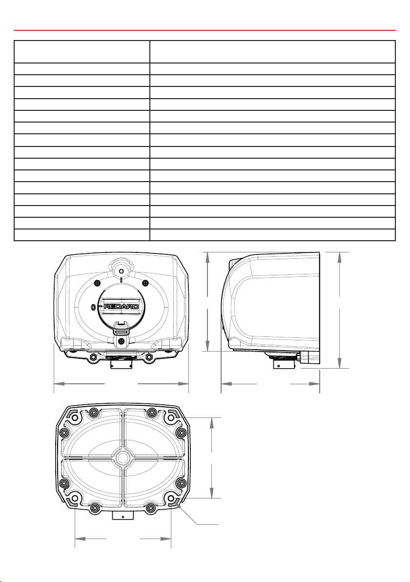
SPECIFICATIONS
Part Numbers BMIS-4PN
BMIS-4PP
Hazardous area protection Not for operation in explosive atmospheres
Housing material GF PBT
Input Voltage 9V to 32V (12V or 24V systems)
Standby Current Draw <30mA
Ambient Operating Temperature -20°C to 70°C
Ambient Operating Humidity 0% to 100%
Current Rating (continuous 20°C) 400A per pole
Current Rating (90s, 20°C) 1500A (12% Duty cycle)
Current Rating (20s, 20°C) 3500A per pole
Field Isolation Current Rating 10A Resistive, 5A (field) inductive
Environmental protection IP66, IP67 & IP69K
Ancillary (Tacho) Current Limit 10mA @ vehicle voltage
Lamp Drive 2W max
Control Inputs (Remote, ROS) 14mA current limited
Weight 3.5kg
218
155
188 160
159
130
ø9mm
3
Page 5
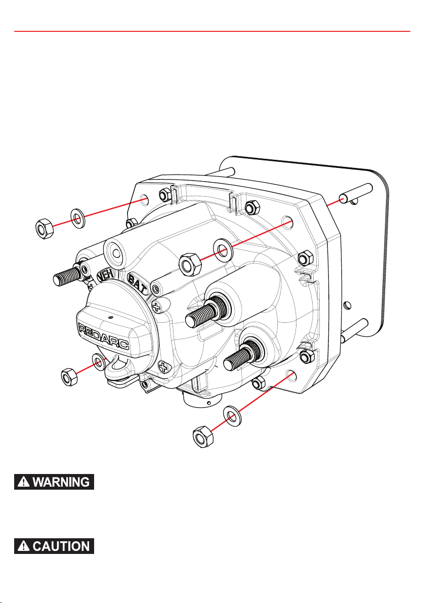
1 INSTALLATION
1.1 Mounting the BMIS
STEP 1.
Bolt the BMIS to a mounting plate with 4 x M8 anti-vibration fasteners and large flat
washers as shown (Grade 8.8 minimum). Recommended to use 19mm OD, 1.6mm Flat
washer as a minimum size.
TORQUE: 10Nm then 20Nm in a cross pattern (to avoid stressing the housing)
ENSURE THAT SWITCH IS OFF BEFORE INSTALLING THE BMIS UNIT (MARKED ‘0’).
ENSURE THAT THE BMIS IS MOUNTED IN THE ORIENTATION AS DEPICTED ON A FLAT PLANE OR USING THE
BMIS-AP. ALTERNATIVE ORIENTATION MAY COMPROMISE CORRECT PRODUCT FUNCTION.
DO NOT ATTEMPT TO OPEN THE UNIT BY REMOVING THE REAR COVER. THIS UNIT IS NOT SERVICEABLE.
4
Page 6

1 INSTALLATION
STEP 2.
Wire the power and ground connections in the order shown below.
TORQUE: 20Nm
4
3
2
1
Alternator
B+ Connection
ENSURE THAT ALL WIRES ARE TERMINATED CORRECTLY.
ENSURE THE SWITCH IS IN THE OFF POSITION (MARKED ‘0’) BEFORE COMMENCING THIS STEP.
THE ALTERNATOR B+ CONNECTION IS TO BE CONNECTED TO THE VEHICLE POSITIVE (TERMINAL3). NO
ADDITIONAL WASHERS TO BE USED ON THE TERMINALS. ENSURE CABLES ARE ALIGNED PROPERLY SO
THEY DO NOT INTERFERE WITH RED COVER.
5
Page 7

1 INSTALLATION
STEP 3.
Insert and secure the Data connector, ensuring that pins align correctly before insertion by
aligning the guides on the plug housing.
The wiring diagram for the data connector is on page 10.
A SEALING PLUG SHOULD BE USED IF DATA CONNECTOR IS NOT USED. IF ALTERNATOR FIELD WINDING NOT
CONNECTED, ACTIVATING THE SWITCH MAY NOT STOP THE ENGINE.
ENSURE THE SWITCH IS IN THE OFF POSITION (MARKED ‘0’) BEFORE COMMENCING THIS STEP.
6
Page 8

1 INSTALLATION
STEP 4.
Place cover on unit and secure with 3 x phillips head screws.
TORQUE: 2Nm
THE RED COVER MUST BE INSTALLED TO PROTECT AGAINST ACCIDENTAL SWITCH ACTIVATION. CONFIRM
OPERATION POST INSTALLATION.
7
Page 9

1 INSTALLATION
STEP 5.
Install Remote Switch and Roll Over Sensor / Roll Over Switch (ROS) if required. Refer to
component supplier instructions.
STEP 6.
Test the unit by switching to ‘on’ position (marked ‘1’) and checking that the indicator led is
lit. The unit should stay in the on position.
• If installed, push the remote switch. This should cause the switch to turn off (marked
‘0’). The LED will also turn off. Ensure field winding is isolated.
• If installed, Test by following Roll Over Switch (ROS) instructions.
LED INDICATOR
CLICK
REMOTE SWITCH
8
Page 10

1 INSTALLATION
1.2 Wiring Connections
1.2.1 BMIS-4PN
BMIS-4PN
Redarc supplied
Customer supplied
Vehicle -ve
Vehicle
+ve
Vehicle
Alternator
1.2.2 BMIS-4PP
Vehicle +ve
Vehicle
+ve
Roll Over
Switch
to Alternator
Field Control
BMIS-4PP
Remote
Switch
Battery
-ve
Battery -ve
Battery +ve
Example
Truck
Wiring
Battery +ve
Battery +ve
Example
Truck
Wiring
Dash
Lamp
(Optional - 2W max)
Redarc supplied
Customer supplied
Dash
Lamp
(Optional - 2W max)
Roll Over
Switch
Vehicle
Alternator
to Alternator
Field Control
Remote
Switch
9
Page 11

1 INSTALLATION
1.3 Data Connector Wiring Diagram
Pin Connections
P
E
F
A
G
H
N
D
M
C
B
J
L
K
Pin 8
Pin 5
Pin 3
Pin 6
Pin 1
REDARC ROS1224
BMIS-4PP Variant Only
M
BMIS-4PN Variant Only
M
F
A
G
H
J
DPST-NO
Remote Switch
ABB push button
recommended P/N
CP6-10R-20
DPST NO switch
D
E
Alternator
C
Field Isolation
B
Optional In-Cab
Field Isolation
ROS Warning
Lamp Output
+12v
Ignition
Ancillary Positive to Radio,
Tachograph, ECU,etc.
(10mA max)
Connection
2W
max
Dash
Warning Lamp
P
N
Roll Over Switch
J
K
Ancillary Negative to Radio,
Tachograph, ECU,etc.
L
ROS -
ROS TRIP
ROS +
(10mA max)
F
A
G
H
GND
Accessories Available
Part number Description
BMIS-CK Deutsch Male Connector Kit
BMIS-AP Big Red/Lucas bolt pattern adapter plate.
ENSURE UNUSED HOLES IN THE CONNECTOR ARE FILLED WITH CAVITY PLUGS AS CONTAMINATION INGRESS
MAY DAMAGE THE BMIS OR CONNECTOR.
DO NOT INSERT MULTIPLE WIRES INTO A SINGLE DEUTSCH CONNECTOR TERMINAL TO PREVENT
CONTAMINATION INGRESS.
10
Page 12

1 INSTALLATION
BMIS
Function Recommended
Pin
M BMIS-4PP Variant
GND or Vehicle negative
(connect to chassis)
BMIS-4PN Variant
Ancillary negative output
(10mA)
L Ancillary positive output
(10mA)
N Field Isolation Switch -
Normally open (fused 10A
max)
P Field Isolation Switch –
Common (fused 10A max)
K Warning Lamp (maximum
2W, fused 1A)
C Remote Switch Supply
negative
B Remote Switch Control Low 0.5-1.5mm
D Remote Switch Control High 0.5-1.5mm
E Remote Switch Supply
positive
J ROS-Data-Warning Lamp
Control
H ROS Control High
Trigger Enable
A ROS Control Low
Trigger
G ROS Supply Positive 0.5-1.5mm
F ROS Supply Negative 0.5-1.5mm
Wire Size
0.5-1.5mm
20-16B&S
0.5-1.5mm
20-16B&S
2
2mm
14B&S
2
2mm
14B&S
0.5-1.5mm
20-16B&S
0.5-1.5mm
20-16B&S
20-16B&S
20-16B&S
0.5-1.5mm
20-16B&S
0.5-1.5mm
20-16B&S
0.5-1.5mm
20-16B&S
0.5-1.5mm
20-16B&S
20-16B&S
20-16B&S
Vehicle iROS Liquip
2
Chassis Ancillary memory power
return from Tacho/radio/ECU if
required
2
Ancillary memory power to
Tacho/radio/ECU if required
Alternator field disconnect
Alternator field disconnect
2
Warning lamp to Ignition switch
positive (optional but recommended)
2
Connect via NO switch contact
to B
2
Connect via NO switch contact
to C
2
Connect via NO switch contact
to E
2
Connect via NO switch contact
to D
2
Black
(optional)
2
Connect
to pin G
2
2
2
Green White PIN 5
Brown Red PIN 3
Blue Green &
RS400
ROS1224
N/A PIN 1
(Optional)
REDARC
Connect
PIN 6
to pin G
PIN 8
Grey
2 USER GUIDE
2.1 Operating the BMIS
TO CONNECT TRUCK POWER:
• Turn the Yellow Handle to the ‘ON’ position (marked ‘1’).
• The LED will be lit.
TO DISCONNECT THE TRUCK POWER
• Turn the Yellow Handle to the ‘OFF’ position (marked ‘0’).
• The LED will not be lit.
11
Page 13

2 USER GUIDE
2.2 LED Indication
• The LED is ON when the truck power is Connected.
• The LED is OFF when the truck power is Disconnected.
• The LED is flashing when the BMIS is in fault or in self test mode.
2.3.1 LED Fault & Self-test Conditions
Faults are indicated by flashing of the Warning Lamp and the LED on the unit. If the LED
is on solid, the unit is working correctly.
Flashing for approximately 2 seconds after the ignition is turned ON and for up to 5
seconds after the isolation switch is turned ON is normal. This indicates the unit is
performing a self test and does not indicate a fault.
Flashing at any other time indicates a problem - see section 2.3.2
2.3.2 Flashing LED Diagnosis
If a Roll Over Switch (ROS) is connected, remove the ROS.
• If the flashing stops, there may be an issue with the ROS.
If a remote switch is fitted, disconnect the remote switch and remote switch harness.
• If the flashing stops, there may be an issue with the remote switch or its associated
harness.
If the flashing continues the BMIS may be faulty.
• Check inside ROS connectors for moisture ingress - including signs of terminal
corrosion and water (droplets).
• Check remote switch for moisture ingress - look for signs of water (droplets),
corrosion (on metallic parts and terminals) or ‘high tide marks’ in enclosures and
inside connectors.
• With ROS disconnected and harness disconnected from BMIS (data connector),
measure resistance between harness circuits for remote switch and ROS - any
2 circuits measuring less than 100kΩ must be checked for moisture ingress and
rectified.
• If LED is not lit, check that you have used the correct part (PN or PP) and that the
switch is on.
• If LED remains on after switch is turned off, check that:
• The battery is connected to the correct side of the switch.
• All circuits are connected through the BMIS.
12
Page 14

3 TROUBLESHOOTING
3.1 Remote Switch
If the remote switch does not work, check that all four wires are connected to the contacts
(DPST type) as per the data connector wiring diagram (figure 1.3). The remote switch will
not work if only two wires are connected to a single contact. Do not short wires together
when connected to the remote switch, this will render the remote switch inoperable with
the Redarc BMIS. When installing or diagnosing the remote switch circuit, Test that a
short circuit on either pole of the remote switch does not cause the BMIS to trigger.
3.2 Troubleshooting Flow-Chart
No LED
ROS does not
operate BMIS
during test
Battery voltage in
operating range?
LED Blinking more
than 30sec after
switching on or 2sec
after cranking
Battery voltage in
operating range?
BMIS turns off
unexpectedly
Remote switch does
not operate BMIS
Battery voltage in
operating range?
PP variant?
Yes
Check continuity from
BMIS Pin M to vehicle GND
Not
Connected
Repair Wiring
Connected
Battery voltage in
operating range?
No
Charge or
replace battery
Yes
Does remote switch
operate BMIS?
No
No Yes Yes
Yes No Ye s
BMIS may be faulty
No
Do shorting pins
H+G and F+A
operate the BMIS?
No Yes
ROS or wiring
may be faulty
Check remote switch
wiring for shorts
or water ingress
OK Not OK
No
Charge or
replace battery
Disconnect ROS Disconnect ROS
BMIS works
correctly
Stops
blinking
Remains
blinking
Disconnect
remote switch
Remains
blinking
Stops
blinking
Still does
not work
Disconnect
remote switch
Still does
not work
BMIS works
Remote switch or
wiring may be faulty
Repair Wiring
correctly
No
Shorts between
remote switch wires?
Yes
Check continuity from
BMIS to remote switch
Connected
Do shorting pins
B+C and D+E
operate the BMIS?
Yes
No
Not
Connected
Repair Wiring
Contact Supplier
13
Page 15

3 TROUBLESHOOTING
3.3 Battery not charging
Check alternator field connections.
• Bridge the field isolation connection at the alternator to verify correct operation.
• Bridge the BMIS harness
4 FAQS
Question: Is the unit protected against voltage spikes?
Answer: Yes, the BMIS incorporates a number of spike protection components
specifically designed to reduce the risk of damaging the unit. The BMIS is also
designed to prevent any spikes being generated by the unit and in turn affecting any
vehicle equipment.
Question: What does the LED indicate?
Answer: The LED indicates the unit is activated and power is available to the vehicle.
A flashing red LED indicates a fault except during the first 5 seconds after turning the
isolation switch on. See section 2.3.1 on page 12.
Question: Can I use the BMIS to shut off the engine?
Answer: Do NOT routinely use the BMIS to shut off the engine except in an emergency
or for routine testing. Use the ignition key as per normal vehicle operation.
It’s recommended to perform an engine shutdown test on a fully charged battery (or
allow a few minutes of engine operation beforehand to recharge the battery as much
as possible). Following these recommendations will minimise the possibility of damage
and/or accelerated wear to vehicle electrical systems.
5 TECH TIPS
When mounting - ensure torque in 2 stages, criss-cross method with torque wrench
Do NOT install star washers between cable lugs and terminals
Ensure cables are straight and do not interfere with the cover/fascia
Flashing LED - check for water or fault connection in wiring harness
Remote switch requires dual pole to operate the BMIS
Make sure the mating Deutsch connector has blanking plugs installed to prevent
potential water ingress
14
Page 16

6 MAINTENANCE & CLEANING
If the BMIS is installed or used in dirty conditions, check and clean on a regular basis.
Do not open the Unit by removing the rear cover.
Clean the unit with warm, soapy water.
• Do Not high pressure clean.
• Periodically check that the screws and nuts are tight and for correct torque on
power on battery and starter motor connections.
• Periodically check isolation switch function in accordance with warnings found on
page 1 of this manual.
DO NOT ALTER OR DISASSEMBLE THE BMIS UNDER ANY CIRCUMSTANCES. THERE ARE NO USER SERVICEABLE
PARTS INSIDE. THE BMIS IS NOT SERVICEABLE AND IS LUBRICATED FOR LIFE. THE BMIS MUST BE RETURNED
TO YOUR SUPPLIER FOR ASSESSMENT. INCORRECT HANDLING, DISASSEMBLY OR REASSEMBLY MAY RESULT IN
A RISK OF ELECTRIC SHOCK OR FIRE AND MAY VOID THE UNIT WARRANTY.
15
Page 17

7 STANDARDS & TESTING
7.1 Standards and Testing
The BMIS 4-PP and 4-PN are Tested/Certified to:
Reference Title
IEC 60529 IP66/67 Degree of protection provided by enclosures
UL94 Tests for flammability of plastic materials for parts in devices and appliances
AS/NZS CISPR 11
GROUP 1 CLASS A
ISO60068-2-74 (MOD)
ISO 8092-2
SAE J1113-11,-12
ISO 7637-2
ISO 11452-10
SAE J1113-4,-21
ISO 11452-2,-4
CISPR25 (MOD)
CLASS 3
IEC 60068-2-30
IEC 60068-2-38
ISO 60068-2-2 Accelerated temperature aging test for electrical and electronic components
ASTM D3170 Gravel bombardment test for electrical and electronic components
ASTM B117 1000Hrs Salt-fog test for electrical and electronic components
ISO 16750-3
IEC 60068-2-64
TEST VII
ISO 10605 Electrostatic discharge (ESD) immunity test requirements
IEC 60068-2-14
ISO 16750-4
IEC 60068-2-2
ISO 16750-4
IEC 60068-2-1
ISO 16750-4
Industrial, scientific and medical (ISM) RF equipment electromagnetic
disturbance characteristics.
Resistance to automotive fluids
Electrical transients for electrical and electronic devices
Electromagnetic-radiated-immunity requirements for electrical and electronic
components
Electromagnetic-radiated emissions for electrical and electronic components
Humidity testing for electrical components
Vibration requirements for electrical/electronic devices, Commercial Vehicle
6g
Temperature cycling test for electrical and electronic components
High temperature test for electrical and electronic components
Low temperature test for electrical and electronic components
16
Page 18

8 NOTES
17
Page 19

9 TWO YEAR PRODUCT WARRANTY
Over the last three decades our company has established a reputation as the power conversion specialist.
A 100% Australian-owned company, we have met the needs of customers in transport and other industries through exciting, innovative thinking.
We believe in total customer satisfaction and practice this by offering our customers:
• Technical advice free of jargon and free of charge
• Prompt turnaround of orders throughout Australia and globally
• Friendly, personalised, professional service and product support
In the unlikely event that a technical issue arises with a Redarc product, customers are encouraged to initially contact the Redarc Technical Support Team on (08) 8322 4848
or power@redarc.com.au for prompt and efficient diagnosis and product support.
Our goods come with guarantees that cannot be excluded under the Australian Consumer Law. You are entitled to a replacement or refund for a major failure and compensation for
any other reasonably foreseeable loss or damage. You are also entitled to have the goods repaired or replaced if the goods fail to be of acceptable quality and the failure does not
amount to a major failure.
The benefits of this Warranty are in addition to other rights and remedies available at law in respect of the Products and shall not derogate from any applicable mandatory statutory
provisions or rights under the Australian Consumer Law.
Redarc Electronics Pty Ltd atf the Redarc Trust trading as Redarc Electronics (“Redarc”) offers a warranty in respect of its Products where the Products are purchased from an
authorised distributor or reseller of Redarc by a person (“Purchaser”), on the terms and conditions, and for the duration, outlined below in this document (“Warranty”).
1. In this Warranty, the term Products means:
1.1 all products manufactured or supplied by Redarc (excluding its solar products
which are covered by Redarc’s Solar Product Warranty); and
1.2 any component of or accessory for any product in clause 1.1 manufactured or
supplied by Redarc.
Offer and duration of product warranties
2. Redarc warrants that its Products will be free, under normal application, installation,
use and service conditions, from defects in materials and workmanship affecting
normal use, for 2 years from the date of purchase (Warranty Period).
3. Where a Product malfunctions or becomes inoperative during the Warranty Period,
due to a defect in materials or workmanship, as determined by Redarc, then subject
to further rights conferred by the Australian Consumer Law on the Purchaser,
Redarc will, in exercise of its sole discretion, either:
3.1 repair the defective Product;
3.2 replace the defective Product; or
3.3 provide a refund to the Purchaser for the purchase price paid for the defective
Product,
without charge to the Purchaser.
4. The warranty given by Redarc in clause 3 covers the reasonable costs of delivery
and installation of any repaired or replaced Products or components of Products
to the Purchaser’s usual residential address notified to Redarc, together with the
reasonable costs of removal and return of any Products determined by Redarc to be
defective.
5. If the Purchaser incurs expenses of the nature referred to in clause 4 in the
context of making a claim pursuant to this Warranty that is accepted by Redarc,
the Purchaser will be entitled to claim for reimbursement of those expenses which
Redarc determines, in exercise of its sole discretion, to be reasonably incurred,
provided that the claim is notified to Redarc in writing at the postal address or email
address specified in clause 21 and includes:
5.1 details of the relevant expenses incurred by the Purchaser; and
5.2 proof of the relevant expenses having been incurred by the Purchaser.
Exclusions and limitations
6. This Warranty will not apply to, or include any defect, damage, fault, failure
or malfunction of a Product, which Redarc determines, in exercise of its sole
discretion, to be due to:
6.1 normal wear and tear or exposure to weather conditions over time;
6.2 accident, misuse, abuse, negligence, vandalism, alteration or modification;
6.3 non-observance of any of the instructions supplied by Redarc, including
instructions concerning installation, configuring, connecting, commissioning,
use or application of the Product, including without limitation choice of location;
6.4 failure to ensure proper maintenance of the Product strictly in accordance with
Redarc’s instructions or failure to ensure proper maintenance of any associated
equipment or machinery;
6.5 repairs to the Product that are not strictly in accordance with Redarc’s
instructions;
6.6 installation, repairs or maintenance of the Product by, or under the supervision
of, a person who is not a qualified auto electrician or technician, or if nongenuine or non-approved parts have been fitted;
6.7 faulty power supply, power failure, electrical spikes or surges, lightning, flood,
storm, hail, extreme heat, fire or other occurrence outside the control of
Redarc;
6.8 use other than for any reasonable purpose for which the Product was
manufactured;
6.9 any indirect or incidental damage of whatever nature outside the control of
Redarc.
7. Warranty claims in respect of a Product must be made in writing to Redarc at the
postal address or email address specified in clause 21 within the Warranty Period.
Such claims must include the following:
7.1 details of the alleged defect or fault and the circumstances surrounding the
defect or fault;
7.2 evidence of the claim, including photographs of the Product (where the subject
of the claim is capable of being photographed);
7.3 the serial number of the Product, specified on the label affixed to the Product;
and
7.4 proof of purchase documentation for the Product from an authorised distributor
or reseller of Redarc, which clearly shows the date and place of purchase.
The return of any Products without the prior written instructions of Redarc will not
be accepted by Redarc.
8. Without limiting any other clause in this Warranty, Redarc has the right to reject any
Warranty claim made by a Purchaser pursuant to this Warranty where:
8.1 the Purchaser does not notify Redarc in writing of a Warranty claim within the
Warranty Period;
8.2 the Purchaser does not notify Redarc in writing of a Warranty claim within 1
month of becoming aware of the relevant circumstances giving rise to the
claim, so that any further problems with the Product are minimised;
8.3 the serial number of the Product has been altered, removed or made illegible
without the written authority of Redarc;
8.4 the Purchaser is unable to provide proof of purchase documentation in
accordance with clause 7.4 or evidence that the Product was properly installed
and removed (if relevant), and that proper maintenance has been performed
on the Product, by, or under the supervision of, a qualified auto electrician or
technician, in accordance with the instructions of Redarc.
9. If the Product is found to be working satisfactorily on return to Redarc or upon
investigation by Redarc, the Purchaser must pay Redarc’s reasonable costs of
testing and investigating the Product in addition to shipping and transportation
charges. Where Redarc is in possession of the Product, the Product will be
returned to the Purchaser on receipt of the amount charged.
10. Any replaced Products or components of Products shall become the property of
Redarc.
11. Redarc may, in exercise of its sole discretion, deliver another type of Product or
component of a Product (different in size, colour, shape, weight, brand and/or
other specifications) in fulfilling its obligations under this Warranty, in the event
that Redarc has discontinued manufacturing or supplying the relevant Product or
component at the time of the Warranty claim, or where such Product or component
is superior to that originally purchased by the Purchaser.
Other conditions of Warranty
12. If the Purchaser acquired a Product for the purpose of resupply, then this Warranty
shall not apply to that Product.
13. In particular, the sale of a Product via an online auction, online store or other
internet website by a party that is not an authorised distributor or reseller of the
Product will be deemed to be a resupply within the meaning of the Australian
Consumer Law and will render this Warranty void, as Redarc has no control over the
storage, handling, quality or safety of Products sold by such persons.
14. A Purchaser shall only be entitled to the benefit of this Warranty after all amounts
owing in respect of the Product have been paid.
15. While Redarc warrants that the Products will be free from defects in materials and
workmanship in the circumstances set out in this Warranty, to the maximum extent
permitted by law Redarc does not warrant that the operation of the Products will be
uninterrupted or error-free.
16. To the maximum extent permitted by law, Redarc’s determination of the existence of
any defect and the cause of any defect will be conclusive.
17. Spare parts or materials for the Products are guaranteed to be available for a period
of at least 2 years after purchase of the Products.
18. The agents, officers and employees of any distributor or reseller of the Products and
of Redarc are not authorised to vary or extend the terms of this Warranty.
19. Redarc shall not be responsible or liable to the Customer or any third party in
connection with any non-performance or delay in performance of any terms and
conditions of this Warranty, due to acts of God, war, riots, strikes, warlike conditions,
plague or other epidemic, fire, flood, blizzard, hurricane, changes of public policies,
terrorism and other events which are beyond the control of Redarc. In such
circumstances, Redarc may suspend performance of this Warranty without liability
for the period of the delay reasonably attributable to such causes.
20. If a clause or part of a clause in this Warranty can be read in a way that makes it
illegal, unenforceable or invalid, but can also be read in a way that makes it legal,
enforceable and valid, it must be read in the latter way. If any clause or part of
a clause in this Warranty is illegal, unenforceable or invalid, that clause or part is
to be treated as removed from this Warranty, but the rest of this Warranty is not
affected.
Redarc’s contact details
21. Redarc’s contact details for the sending of Warranty claims under this Warranty are:
REDARC Electronics Pty Ltd
23 Brodie Road (North), Lonsdale SA 5160
Email: power@redarc.com.au
Telephone: +61 8 8322 4848
18
Page 20

Free technical assistance!
please contact
REDARC Electronics
23 Brodie Road North, Lonsdale SA
+61 8 8322 4848
power@redarc.com.au
www.redarc.com.au
Copyright © 2017 REDARC Electronics Pty Ltd. All rights reserved.
WARBMIS - REV8
www.redarc.com.au
 Loading...